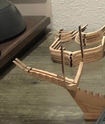
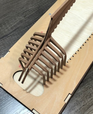
Thank you, Luiz, and welcome aboard.Daniel, very beautiful and detailed kit. I'm sure it will be an excellent model. Keep us posted, good luck
-

Win a Free Custom Engraved Brass Coin!!!
As a way to introduce our brass coins to the community, we will raffle off a free coin during the month of August. Follow link ABOVE for instructions for entering.
-

PRE-ORDER SHIPS IN SCALE TODAY!
The beloved Ships in Scale Magazine is back and charting a new course for 2026!
Discover new skills, new techniques, and new inspirations in every issue.
NOTE THAT OUR FIRST ISSUE WILL BE JAN/FEB 2026
- Home
- Forums
- Ships of Scale Group Builds and Projects
- Bluenose PoF Group Build
- Bluenose Group Build Logs
You are using an out of date browser. It may not display this or other websites correctly.
You should upgrade or use an alternative browser.
You should upgrade or use an alternative browser.
The Schooner Bluenose 1921, POF Yuanqing Models 1:72 [COMPLETED BUILD]
I don’t usually use the long reach plastic clamps, but they have them for sale at grainger and other places.Good advice Dean, I have 7 frames glued up, no sanding yet. I've checked and double checked more times than I care to admit concerning bevel direction inside and out and yes, the direction changes past the wide part going toward the stern. Where do you get those needle nose long reach spring clamps, I've looked everywhere. I can find long reach, but they are too big and use too much pressure.
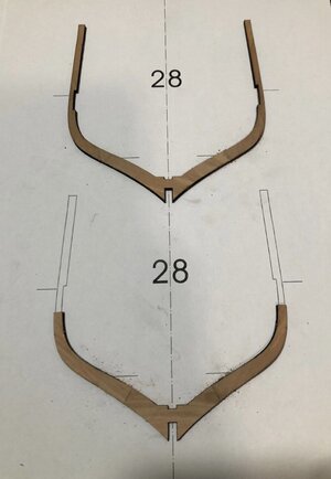
I used the full scale pages to do the frame halves first, then I used a board the same size as the keel to align the halves and clamped them together. Then you don’t need long reach clamps.
Last edited:
I see, makes perfect sense, thanks Dean. I have noticed squaring of the glue joints is required otherwise you get an open "V" groove joint.I don’t usually use the long reach plastic clamps, but they have them for sale at grainger and other places.
I used the full scale pages to do the frame halves first, then I used a board the same size as the keel to align the halves and clamped them together. Then you don’t need long reach clamps.
View attachment 358602
Yes, this was discussed before, the lazer beam creates an angled surface, not completely square. Just don't be overzealous and remove enough material to change the shape of the frame!I see, makes perfect sense, thanks Dean. I have noticed squaring of the glue joints is required otherwise you get an open "V" groove joint.
Good afternoon, all.
Here are some additional photos and what I have learned so far. I was gluing up the ribs all at one time which was making me look for some long reach clamps to hold the multiple pieces at bay. Thanks to @Dean62 he showed me a better way to construct without the hassle of multi clamps (see above post #43 for explanation). One of those simple solutions I am grateful for.
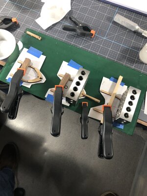
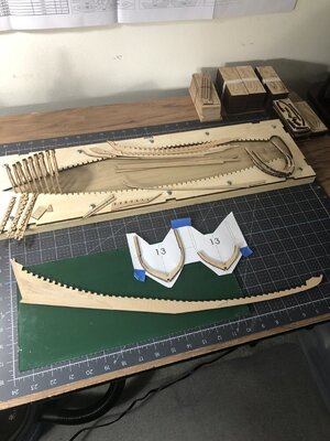
Above, you can see I started on the keel in between drying time for the ribs. The 1st through 8th rib is just dry fit at this time and are only 80% sanded. I will need to add tree nails to them before sanding out the faces. You will see a small amount of char on the exterior edges all the way up to the final fairing step.
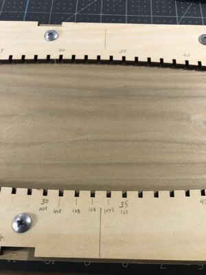
Above I've indicated where the fairing direction will change going towards the stern. This just keeps it straight in my mind.
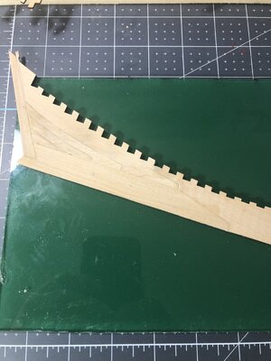
And last for now I had a little problem with join up at the stern keel, see the filler, it should be mostly covered when finished and hopefully will not create problems down the road.
So, thanks for checking in and Happy Modeling.
Here are some additional photos and what I have learned so far. I was gluing up the ribs all at one time which was making me look for some long reach clamps to hold the multiple pieces at bay. Thanks to @Dean62 he showed me a better way to construct without the hassle of multi clamps (see above post #43 for explanation). One of those simple solutions I am grateful for.


Above, you can see I started on the keel in between drying time for the ribs. The 1st through 8th rib is just dry fit at this time and are only 80% sanded. I will need to add tree nails to them before sanding out the faces. You will see a small amount of char on the exterior edges all the way up to the final fairing step.

Above I've indicated where the fairing direction will change going towards the stern. This just keeps it straight in my mind.
And last for now I had a little problem with join up at the stern keel, see the filler, it should be mostly covered when finished and hopefully will not create problems down the road.

So, thanks for checking in and Happy Modeling.
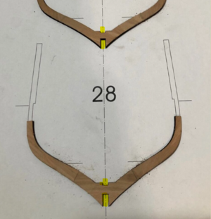
Hey Daniel, glad the tip is helping. One other thing, be sure you use a board top and bottom, to ensure the best alignment...sorry I didn't make that clear in my first post. See highlighted below in yellow...
On the keel stern area, that is odd! It is almost like the part was not correct?
The most important thing is the frame spacing... one to another! It appears you had to space the upper part of the stern keel back towards the stern in an effort to make things fit better. however the frame space might be effected as highlighted below...
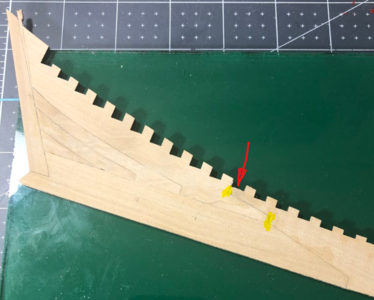
Once the upper most part of the keel is attached, it will be located from the last frame opening. All this determines the frame locations at the stern. The end of the keel where you used a shim, is only the location of the rudder, which can be adjusted easily. Whatever you do, don't change the location of any frames from one another. The keelson will tell you if you are okay on the keel.
Hope that makes sense to you?

On the keel stern area, that is odd! It is almost like the part was not correct?
The most important thing is the frame spacing... one to another! It appears you had to space the upper part of the stern keel back towards the stern in an effort to make things fit better. however the frame space might be effected as highlighted below...

Once the upper most part of the keel is attached, it will be located from the last frame opening. All this determines the frame locations at the stern. The end of the keel where you used a shim, is only the location of the rudder, which can be adjusted easily. Whatever you do, don't change the location of any frames from one another.
Hope that makes sense to you?
You should be able to lay this (stem/keel/stern) on the full-size plan and see how things are matching up. I'm with Dean - there is little room for latitude here.Hey Daniel, glad the tip is helping. One other thing, be sure you use a board top and bottom, to ensure the best alignment...sorry I didn't make that clear in my first post. See highlighted below in yellow...
View attachment 358787
On the keel stern area, that is odd! It is almost like the part was not correct?
The most important thing is the frame spacing... one to another! It appears you had to space the upper part of the stern keel back towards the stern in an effort to make things fit better. however the frame space might be effected as highlighted below...
View attachment 358793
Once the upper most part of the keel is attached, it will be located from the last frame opening. All this determines the frame locations at the stern. The end of the keel where you used a shim, is only the location of the rudder, which can be adjusted easily. Whatever you do, don't change the location of any frames from one another.The keelson will tell you if you are okay on the keel.
Hope that makes sense to you?
Yes, perfect sense, in the back of my mind I was going to hold the correct frame positions regardless. I did make a piece to hold the keel slots even.
If you move that one piece, every frame located on it will be off by that same amount. But don't panic, it will lengthen the ship by that amount (which is very small) and the waterway boards and deck will have to be adjusted potentially, But that is not that bad. You will find anything that is off, will effect something else that comes after it. So this frame skeleton you are creating, is the backbone or foundation of the whole ship. Not trying to be rhetorical, just reminding you! But once again, adjustments can be made. So be slow and methodical to ensure this is as true as you can possibly manage, as it will pay off in dividends later in the build.Yes, perfect sense, in the back of my mind I was going to hold the correct frame positions regardless. I did make a piece to hold the keel slots even.
When I glued my frames in the keel, I used spacer boards to ensure the frames couldn't twist and cause issues at the deck beam level. Any angle out of square effects frame spacing at the top.
Last edited:
Yup your right Dean, frame #40 thru #49 would be shifted 1mm towards the stern therefore I will file 1mm of those notches 1mm to the bow end and make sure the fit is to the bow end and problem should be solved.Hey Daniel, glad the tip is helping. One other thing, be sure you use a board top and bottom, to ensure the best alignment...sorry I didn't make that clear in my first post. See highlighted below in yellow...
View attachment 358787
On the keel stern area, that is odd! It is almost like the part was not correct?
The most important thing is the frame spacing... one to another! It appears you had to space the upper part of the stern keel back towards the stern in an effort to make things fit better. however the frame space might be effected as highlighted below...
View attachment 358793
Once the upper most part of the keel is attached, it will be located from the last frame opening. All this determines the frame locations at the stern. The end of the keel where you used a shim, is only the location of the rudder, which can be adjusted easily. Whatever you do, don't change the location of any frames from one another.The keelson will tell you if you are okay on the keel.
Hope that makes sense to you?
I wished I had a longitude 1:1 cross section but I don't so I used the jig itself by laying the keel sideways on it. It does bear out the error, but I believe I can overcome this, thank goodness the offset was only a millimeter. And yes, a slight error will propagate itself in these situations.You should be able to lay this (stem/keel/stern) on the full-size plan and see how things are matching up. I'm with Dean - there is little room for latitude here.
Hmm. Which still leaves the height of the frames off. I'm not sure how precise things need to be on this BN kit and I would hate for you to have problems later that could be avoided. But since I'm working on my first POF build I'll shut up now.Yup your right Dean, frame #40 thru #49 would be shifted 1mm towards the stern therefore I will file 1mm of those notches 1mm to the bow end and make sure the fit is to the bow end and problem should be solved.

I spent many years in the field laying out bridge bents and abutments always striving to have the finish product come out within a quarter inch. The superintendents would get irritated and say were not building a piano here Thomason so hurry up. It would seem you and I might could build a piano when all this is done. I know Dean could now if he wantedHmm. Which still leaves the height of the frames off. I'm not sure how precise things need to be on this BN kit and I would hate for you to have problems later that could be avoided. But since I'm working on my first POF build I'll shut up now.
Ha! Too late, I already saw it. The do over or in this case fortunately is just a slight modification. The challenge continues Johan.Reply withdrawn, totally superfluous...

- Joined
- Sep 3, 2021
- Messages
- 5,198
- Points
- 738

Ha! Too late, I already saw it. The do over or in this case fortunately is just a slight modification. The challenge continues Johan.
Be sure to use a 1mm shim on the stern side of the slot. And keep those edges parallel and vertical with respect to the deck, not the bottom of the keel.Yup your right Dean, frame #40 thru #49 would be shifted 1mm towards the stern therefore I will file 1mm of those notches 1mm to the bow end and make sure the fit is to the bow end and problem should be solved.
In addition, after cutting your frame notches 1mm towards the bow, I would place a frame in there and glue a shim in place on the stern side, so that it’s snug. Then you can trim and or sand the shim once dried, and the frame is removed. Just a thought. 
If he maintains the bottom horizontal edge of the frame slot, moving the face towards the bow will not change the frame height. But this only because the bottom of the piece that was shifted is horizontal.Hmm. Which still leaves the height of the frames off. I'm not sure how precise things need to be on this BN kit and I would hate for you to have problems later that could be avoided. But since I'm working on my first POF build I'll shut up now.


