
Francois, you never cease to amaze me. I've never seen real coil springs painted before; that's just outstanding detail. Thank you for sharing.

-

SUBSCRIBE TO SHIPS IN SCALE TODAY!
The beloved Ships in Scale Magazine is back and charting a new course for 2026!
Discover new skills, new techniques, and new inspirations in every issue.
NOTE THAT OUR NEXT ISSUE WILL BE MARCH/APRIL 2026 -

Win a Free Custom Engraved Brass Coin!!!
As a way to introduce our brass coins to the community, we will raffle off a free coin during the month of August. Follow link ABOVE for instructions for entering.
- Home
- Forums
- Ships of Scale Build Logs
- Super Detailing Static Models / Other Genres
- Historical Trailways, Guns, Aircraft, and Cars
You are using an out of date browser. It may not display this or other websites correctly.
You should upgrade or use an alternative browser.
You should upgrade or use an alternative browser.

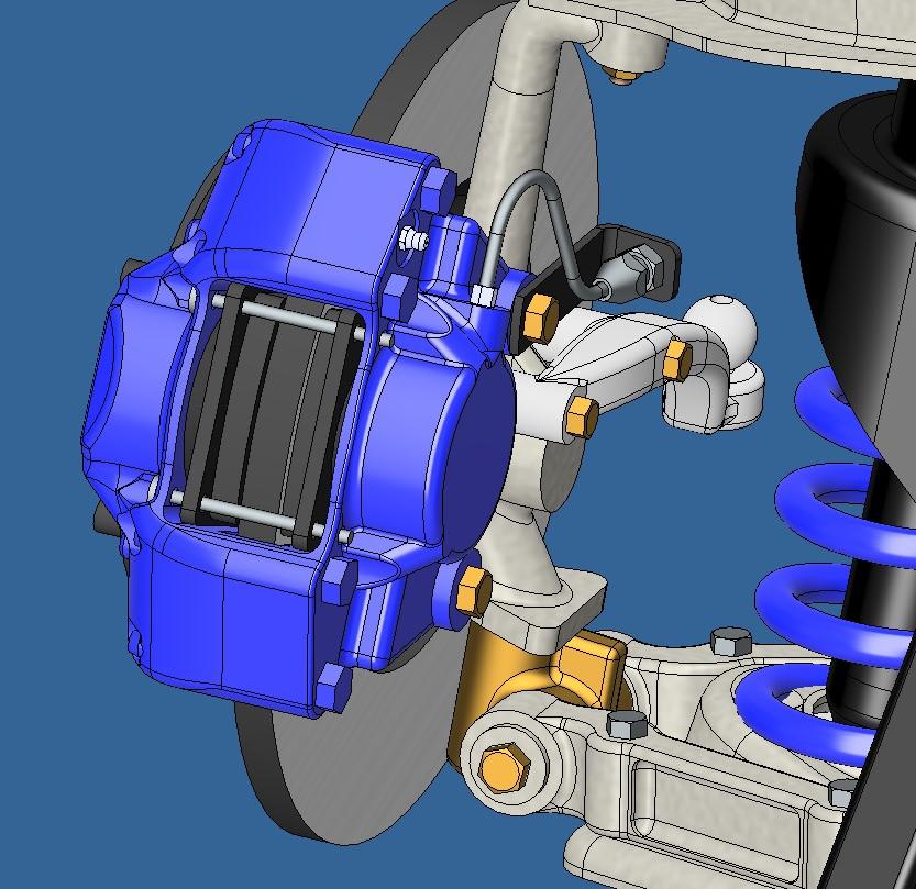
So the calipers are finished. I added the rigid fluid line and the brake pads. I also started the rack and pinion. I'm aiming at a working rack but I've never modeled one before. It will be interesting to see if I can pull it off.
Finished the wheels today and the front axel. I wanted to find an easy way to remove the wheels. My first idea was to do like i did with the Hydra, to use the center cap as a screw. But then I thought of another idea, magnets. I'll inbed 2 magnets in the each hubs and 2 in each wheels. I'll test it before going final with it.
The finished wheel

Vs the real one

The magnet idea

The finished wheel
Vs the real one
The magnet idea
- Joined
- Jul 18, 2024
- Messages
- 496
- Points
- 323

No clue why I missed this, but here I am, looking over your shoulder. Magnificent car and really interesting to see how you proceed in 3D.
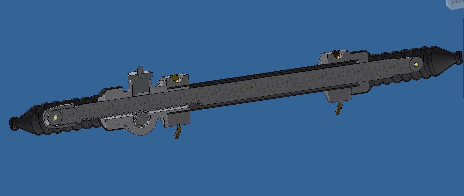
I've been doing some printing test these past few days. I have a working rack and pinion with working rod ends. I still need to refine it here and there but it's close. And I've ordered a miniature steel universal joint (5$ on Temu) to replace the printed ones as it will probably be a weak point in the steering mecanism.
All components in the rack and pinion
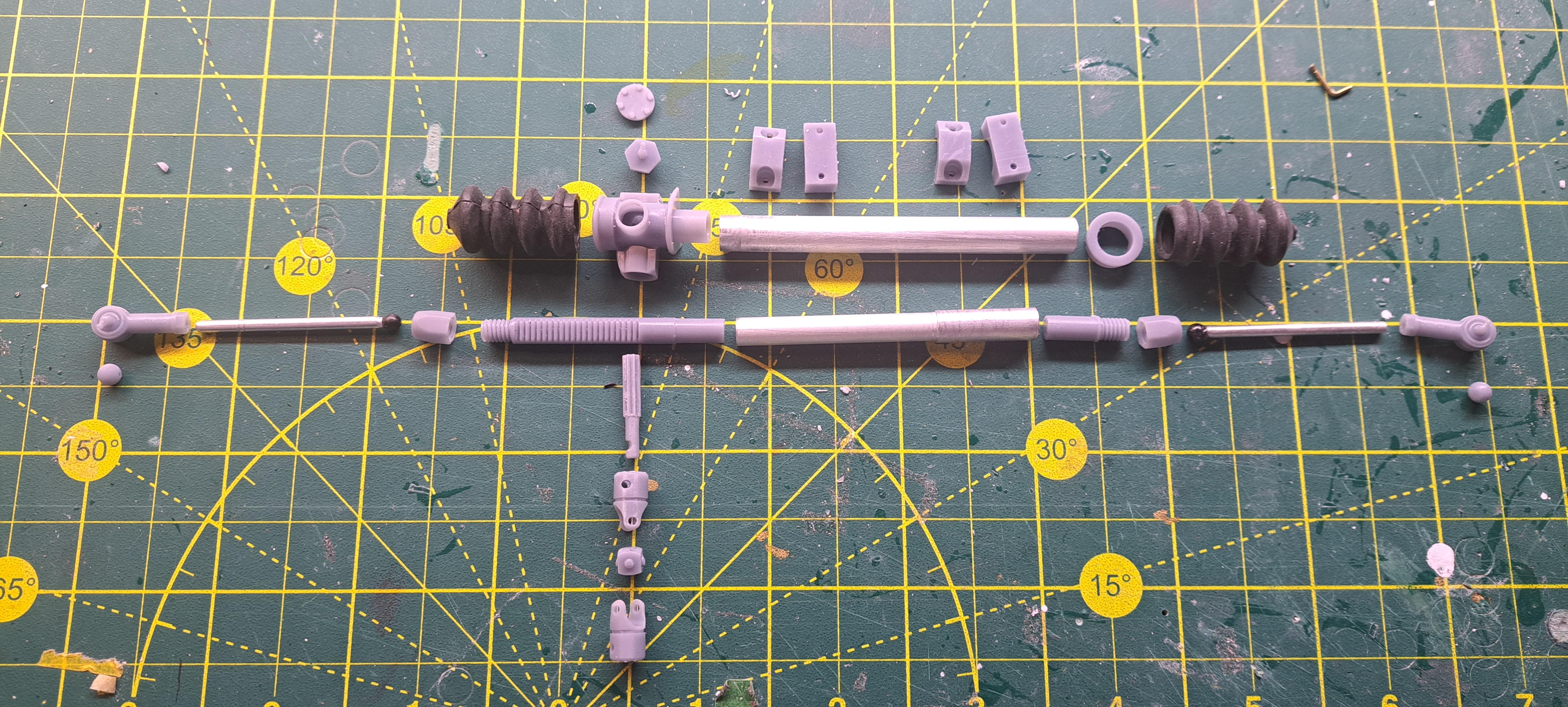
And assembled
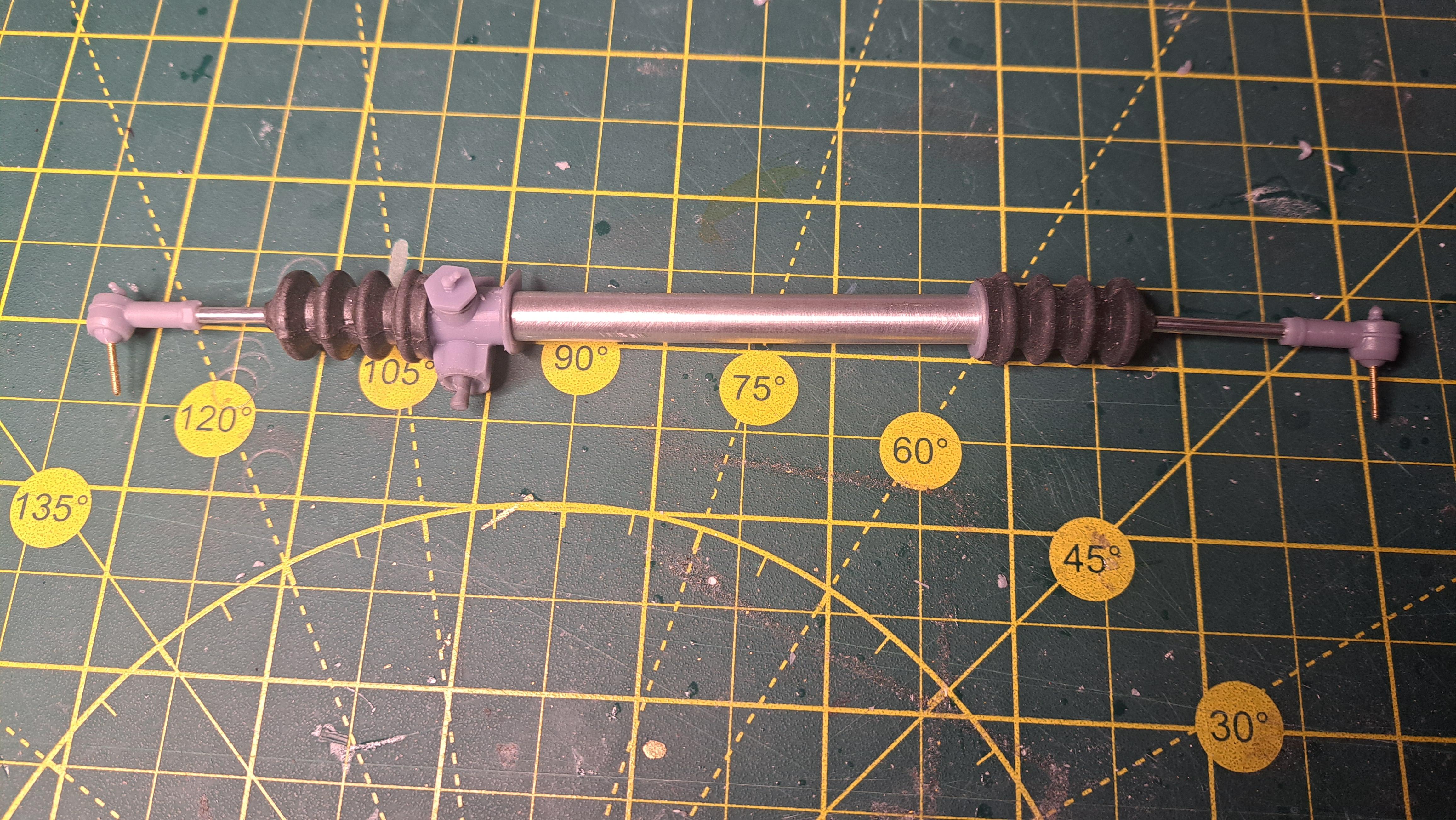
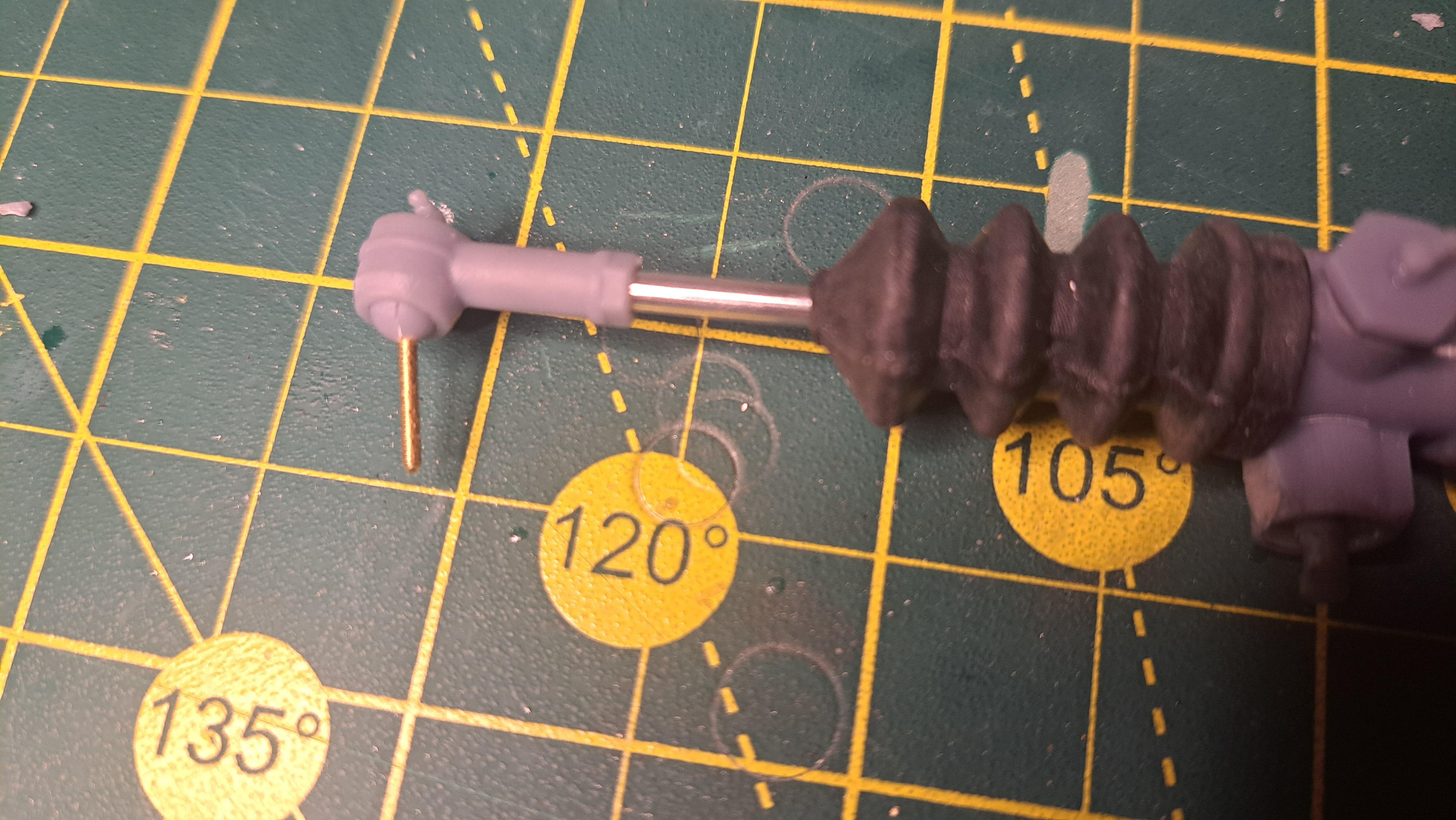
Working rod end with rubber booth (the boot comes from an RC boat I think)
I also printed a complete wheel assembly, I am very pleased with the result. I tested my magnet idea to hold the wheel to the rotor and it works very well. It will be a breeze to remove the wheels to show the suspension.
All components in 1 wheel
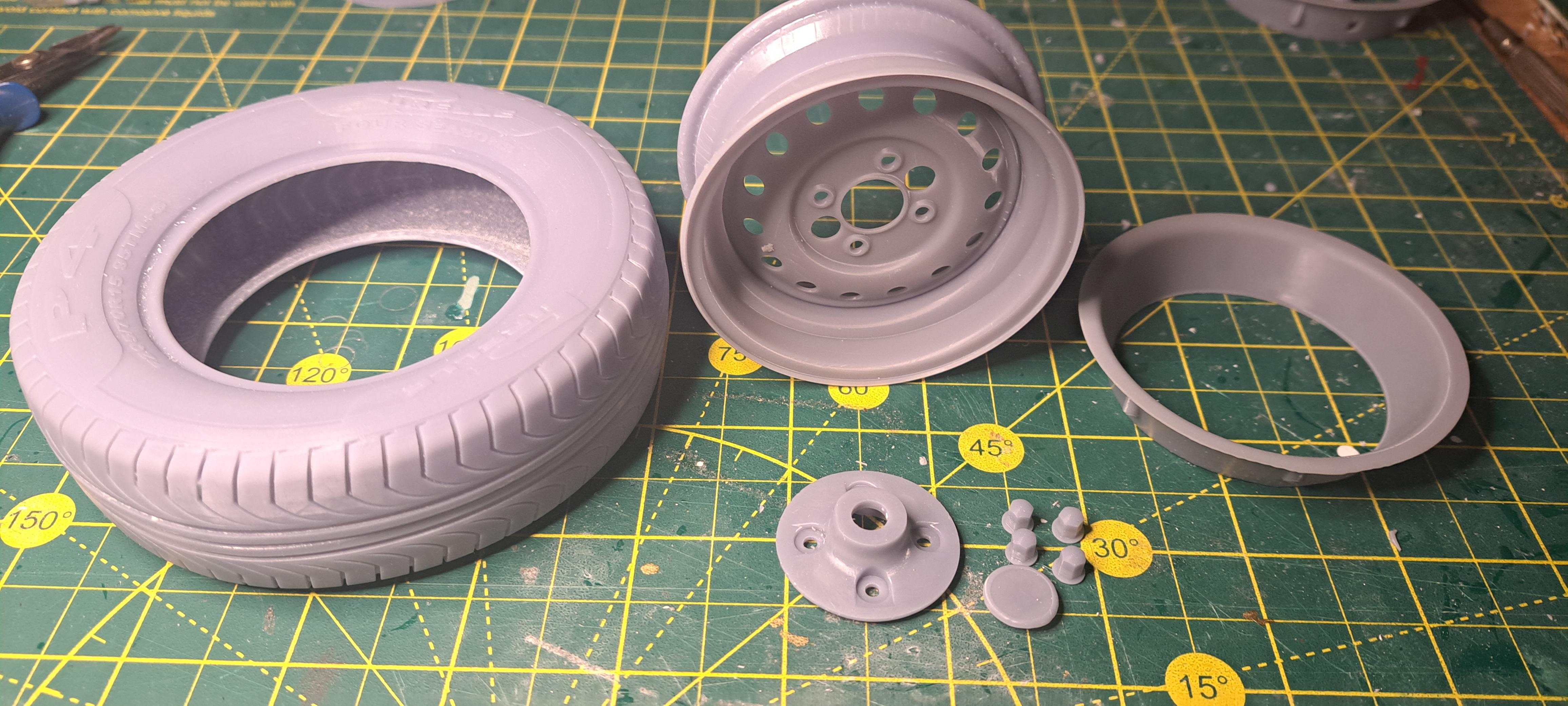
And assembled
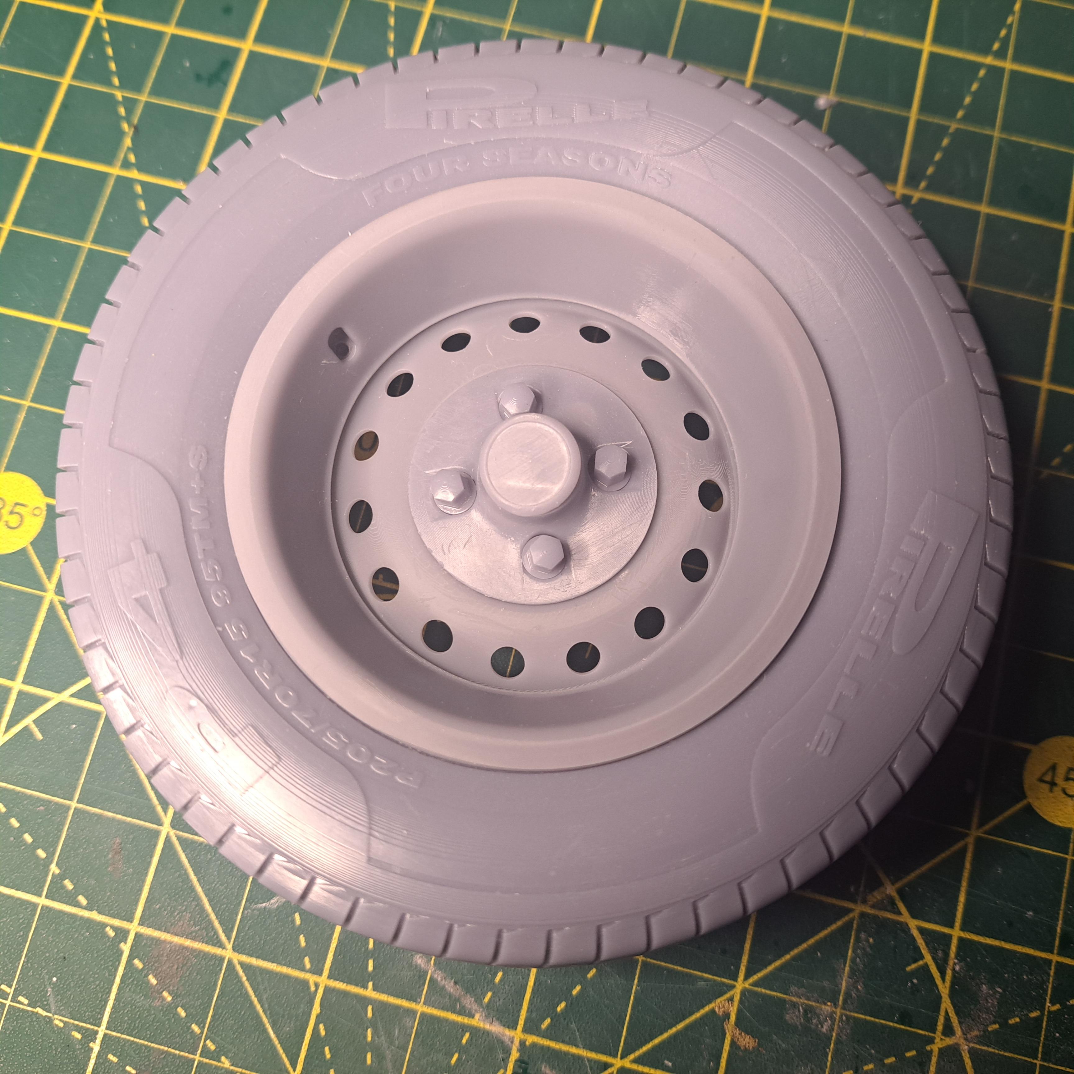
And the real one
All components in the rack and pinion
And assembled
Working rod end with rubber booth (the boot comes from an RC boat I think)
I also printed a complete wheel assembly, I am very pleased with the result. I tested my magnet idea to hold the wheel to the rotor and it works very well. It will be a breeze to remove the wheels to show the suspension.
All components in 1 wheel
And assembled
And the real one
- Joined
- Jul 18, 2024
- Messages
- 496
- Points
- 323
Magnificent. Are you doing this fdm? The smoothness and detail made me think resin. But the small ridges on the tire suggest filament.
Marquinius, it's all resin. Large tires are hard to print due to the big convex surface. I'm testing with different anti- aliasing settings that should help blurr the ridges. If this doesn't help, I'll have to rely on a bit of sanding before paint. About the tire, it was noted to me that I made a major typo. It's should read Pirelli, not Pirelle. Error fixed, sorry to all Pirelli fans.
Well, I did some printing tests on the tire with a different anti aliasing setting and althought not perfect, it aided a bit. I also reduced the lettering height ftom .01 inc to .005 inc. But I will still need to sand. I did try to sand and paint a test tire. I can see that the end result will be good but since I had very little black rubber paint left and had to thin it a bit (read too much), I will not show you my test (I've have to much pride).
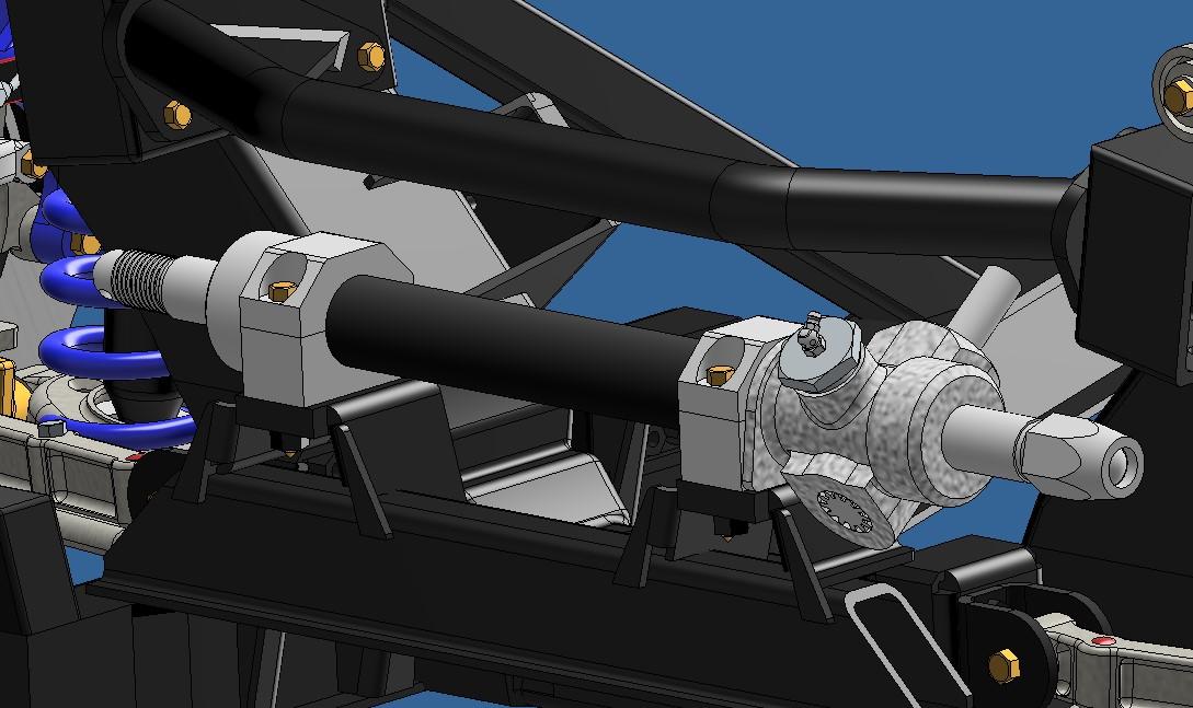
On another front, I have a first sub assembly done, the rack and pinion. Very pleased with the result.

View attachment 20251107_140420.mp4
Now before progressing any further with the frame and rear suspension 3d modeling, l will test print the front suspension components to see if everything fits and moves correctly.
On another front, I have a first sub assembly done, the rack and pinion. Very pleased with the result.
View attachment 20251107_140420.mp4
Now before progressing any further with the frame and rear suspension 3d modeling, l will test print the front suspension components to see if everything fits and moves correctly.
Front suspension test print done and everything seems ok. I'll know for sure once I wash the parts. 
Ok, so here's where I'm at.
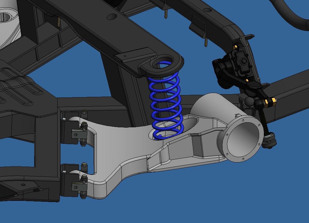
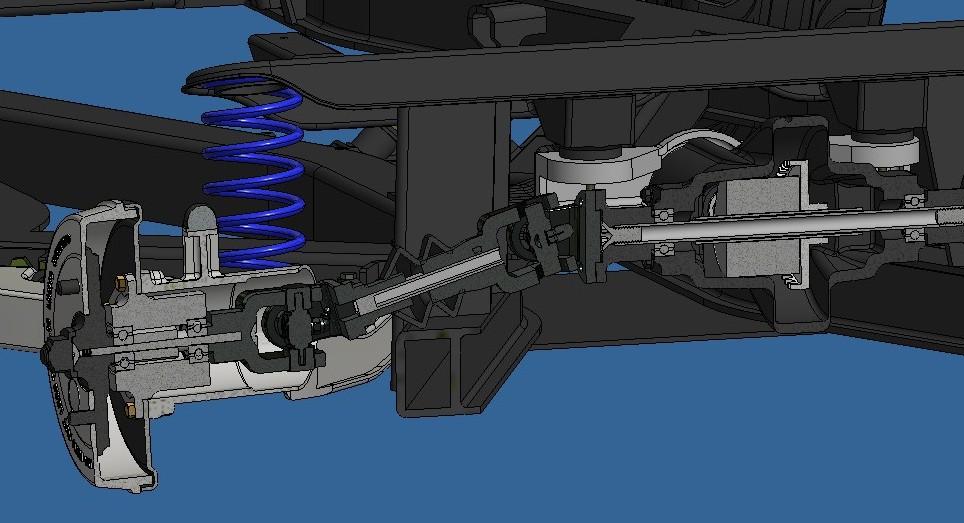
I test printed the drivers side suspension components along with the from portion of the frame. Everything went together fairly easily, didn't have to make many modifications. I did have to hide a secondary compression spring inside the shock absorber since the printed coil spring is too weak. I'll probably end up using real springs instead of the printed ones. I just need to find the correct size. Remember, this is only a mockup so nothing is sanded or finished. I just wanted to confirm that the geometry was ok.
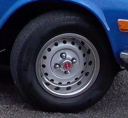
I also painted a wheel to see what it looks like but again, only a mockup. I didn't paint the ring yet since i'm out of chrome paint. I ordered a new type of chrome paint from Green Stuff, apparently, it's more touch resistant then the revell. I was able to confirm that using 2 magnets to hold the wheel in place is a good idea.
Here are some pictures


And some videos
View attachment 20251110_145840.mp4
View attachment 20251110_150258.mp4
I test printed the drivers side suspension components along with the from portion of the frame. Everything went together fairly easily, didn't have to make many modifications. I did have to hide a secondary compression spring inside the shock absorber since the printed coil spring is too weak. I'll probably end up using real springs instead of the printed ones. I just need to find the correct size. Remember, this is only a mockup so nothing is sanded or finished. I just wanted to confirm that the geometry was ok.
I also painted a wheel to see what it looks like but again, only a mockup. I didn't paint the ring yet since i'm out of chrome paint. I ordered a new type of chrome paint from Green Stuff, apparently, it's more touch resistant then the revell. I was able to confirm that using 2 magnets to hold the wheel in place is a good idea.
Here are some pictures
And some videos
View attachment 20251110_145840.mp4
View attachment 20251110_150258.mp4

I find the detail absolutely outstanding. Great combination of top-notch design skills, and a good printer.

Again a very nice outcome of your first printed parts, François. Fascinating!Ok, so here's where I'm at.
I test printed the drivers side suspension components along with the from portion of the frame. Everything went together fairly easily, didn't have to make many modifications. I did have to hide a secondary compression spring inside the shock absorber since the printed coil spring is too weak. I'll probably end up using real springs instead of the printed ones. I just need to find the correct size. Remember, this is only a mockup so nothing is sanded or finished. I just wanted to confirm that the geometry was ok.
I also painted a wheel to see what it looks like but again, only a mockup. I didn't paint the ring yet since i'm out of chrome paint. I ordered a new type of chrome paint from Green Stuff, apparently, it's more touch resistant then the revell. I was able to confirm that using 2 magnets to hold the wheel in place is a good idea.
Here are some pictures
And some videos
View attachment 556077
View attachment 556078
Regards, Peter.
- Joined
- Jul 18, 2024
- Messages
- 496
- Points
- 323
Absolutely top notch!
As an aside: I just bought a can of Siraya tech tenacious. That should be more flexible and perhaps worth investigating for tires.
Haven’t used it yet: more curious than required for current project.
As an aside: I just bought a can of Siraya tech tenacious. That should be more flexible and perhaps worth investigating for tires.
Haven’t used it yet: more curious than required for current project.
Beautiful work François, paint makes that plastic look like the real thing.
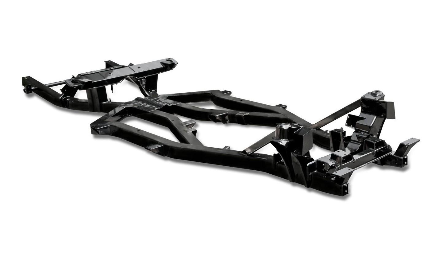
I've been busy 3d modeling the last 2 days. The frame is pretty much finished, all that is left to do is to split it in printable sections. Probably 3. I also started on the rear suspension, I have the lever shock done and am trying to do the swing arms. These are very complex parts with many planes and axes, not one being square or parallel to another. I'll figure it out eventually.
The finished frame model
.jpg.0dbd5678f1b827f81318985be7e03cec.jpg)
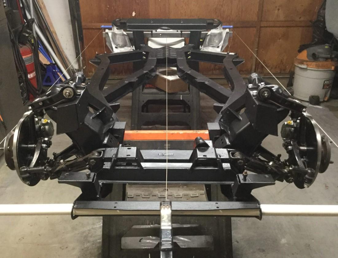
compared to a real frame
Rear suspension bits
Vs real bits
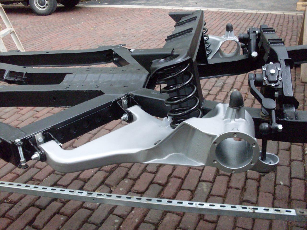
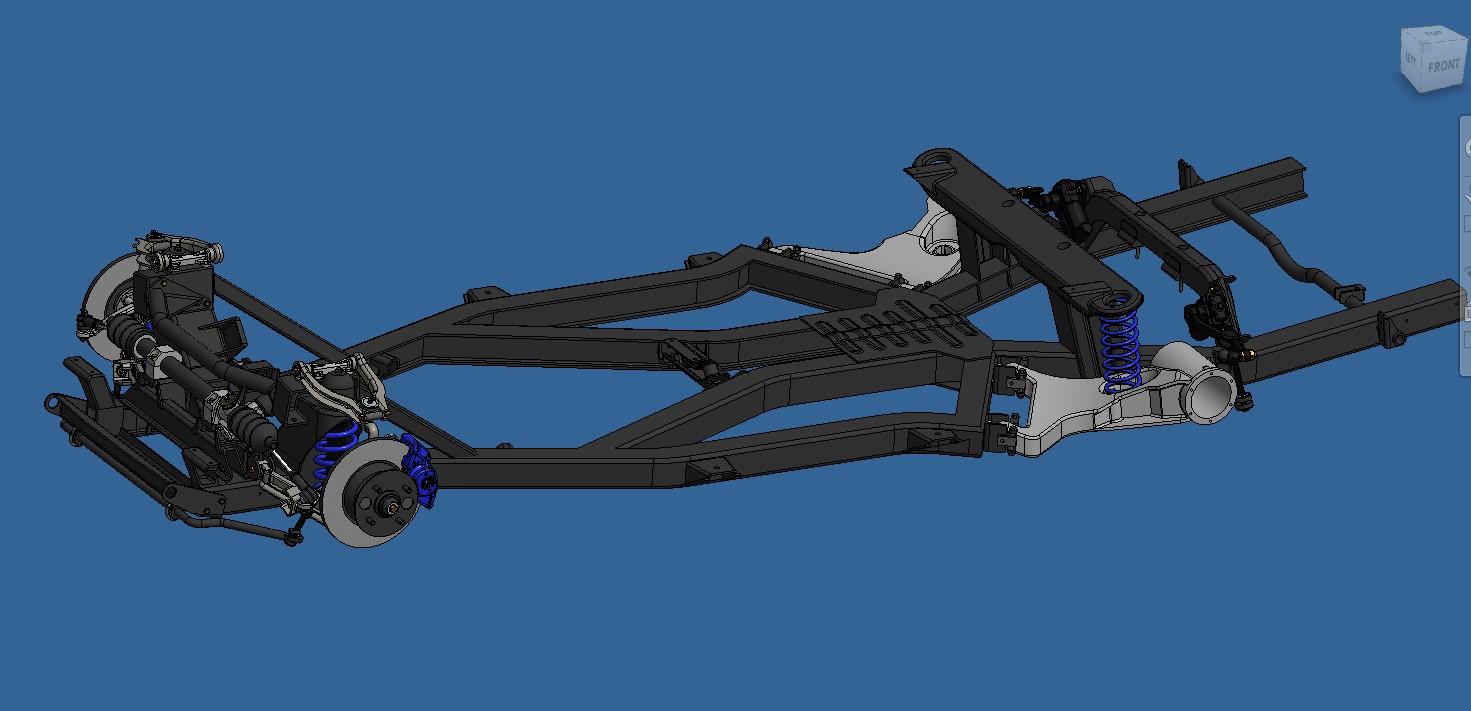
And an overall view
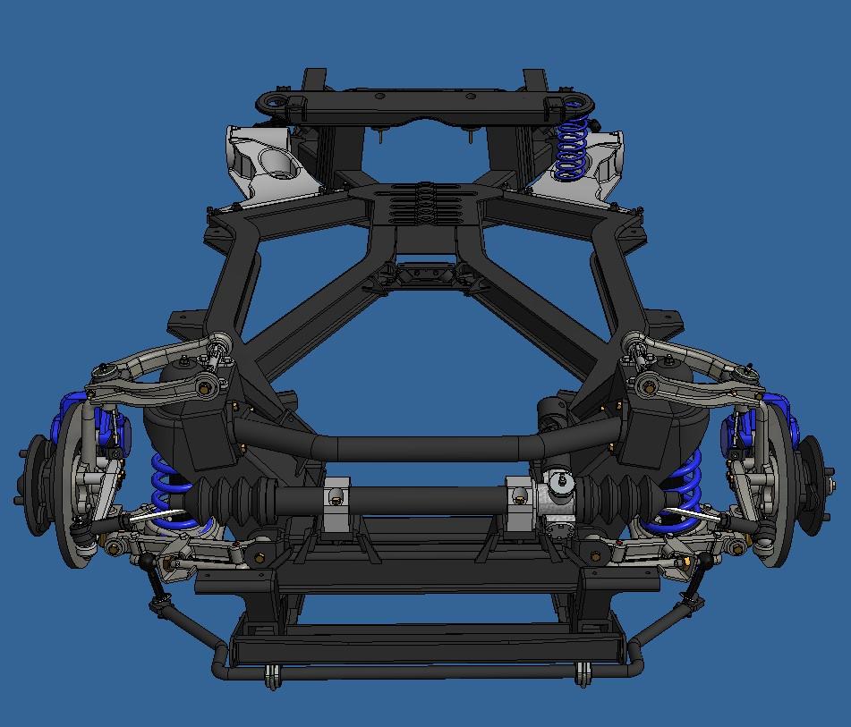
Compared to the resl thing (not mine)
The finished frame model
compared to a real frame
Rear suspension bits
Vs real bits
And an overall view
Compared to the resl thing (not mine)


Yeah I know, what a dumb typo. It's been fixed along with a better looking 'P'.

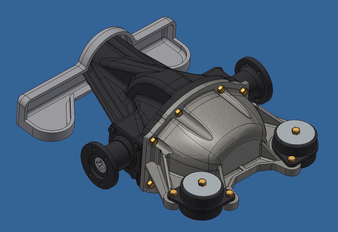
I started this project stating that I wanted a running engine and drive train as I did on the Hydra. I would also like it to be a better design. The hydra motor broke, yes because the weak point was the crank but also because there was a lot of friction from the different rotating components. So I'm trying to reduce this friction by using ball bearings wherever possible. I'll have then at the rear hubs, inside the differentiel, the transmission and, if possible, the engine. I bought a bunch of 3mm id x 7mm od x 3mm thk bearings. With this in mind, I 3d modeled the rear drive train and differentiel today. It's not 100% finished but it's close. Inside the differentiel, I'll probably use the same setup as I used on the hydra which means it's not a real differentiel but rather a 90 deg gearbox. I also finished the trailing arms, I got them looking a lot more like the real ones now.
Almost finished differentiel
Trailing arm with drum and half shaft
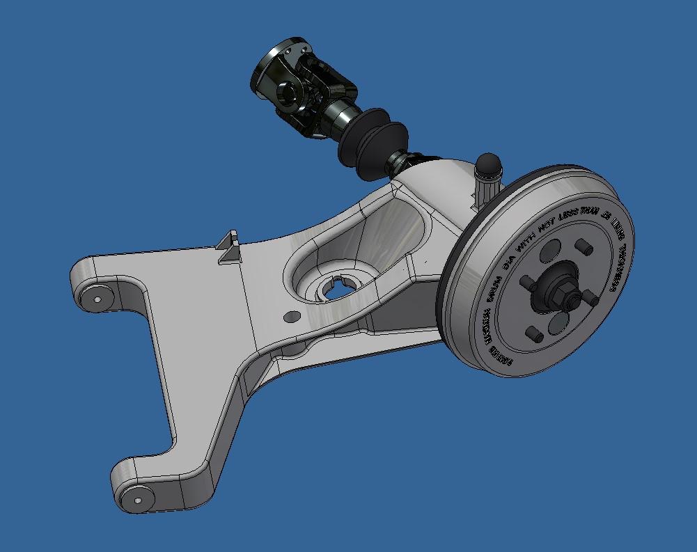
cross section of rear drive train with bearings in place (not final yet)
Almost finished differentiel
Trailing arm with drum and half shaft
cross section of rear drive train with bearings in place (not final yet)
- Joined
- Jul 18, 2024
- Messages
- 496
- Points
- 323
You make it sound simple. Of course you use 3mm bearings.