• Win a Free Custom Engraved Brass Coin!!!
    As a way to introduce our brass coins to the community, we will raffle off a free coin during the month of August. Follow link ABOVE for instructions for entering.

Triumph Tr6, 3d printed large scale

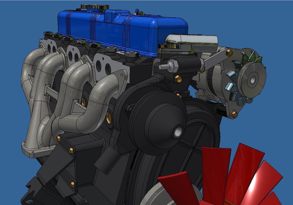
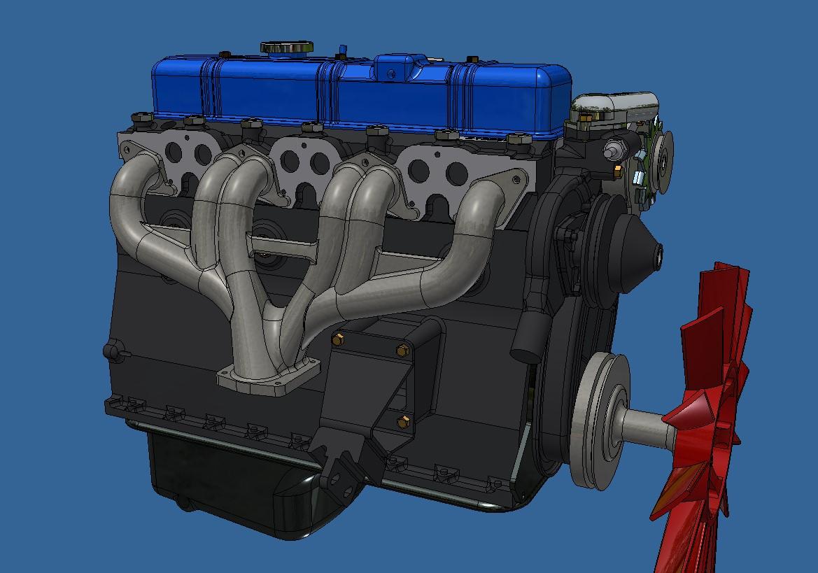
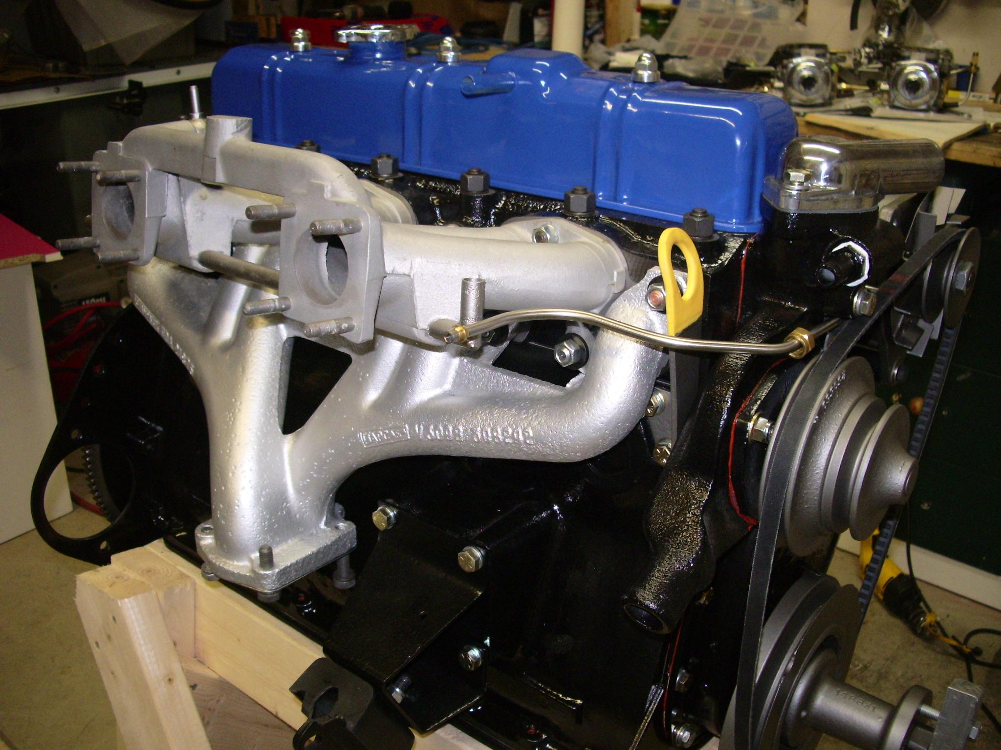
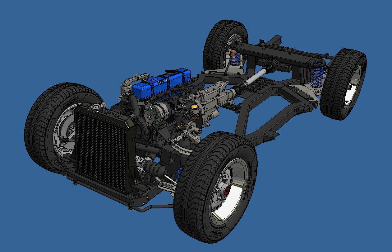
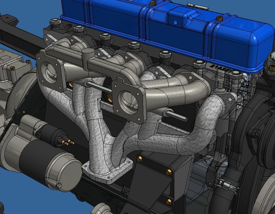
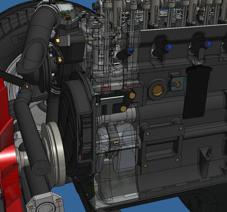
I'm almost done with the engine. I still need to do the intake manifold and the carburators, I'm keeping the carbs for last since they are quite complicated. The Stromberg carburators were one of the things a TR6 was known for so I want to get them as right as I can. Once all of this is done, I have to figure out how to showcase all these moving parts. The rocker cover and oil pan will be removable, that's a given. But i'd like to dive in deeper and look at the valves, pistons and conrods as they move. I might make a few cut-outs here and there, not to sure just how yet.

Capturedcran2025-12-08191745.jpg.7f34d1f422dd7e274e17bb07561511fe.jpg


Capturedcran2025-12-08191757.jpg.4645be447b0918ac80f19aa146bb2945.jpg


IMGP2868.JPG.9cead3eebb6745ed34dddf2cbe1f7fdf.JPG
 
I think what would be really fun is a video of you designing some parts. I don't think I've ever met anyone who works so fast designing stuff! You are making me consider switching from SolidWorks to Inventor!
 
Ok so, here's where I'm at as of today.

Aside from the carburators, the engine is done. I now have what I like to call a 'digital rolling chassis'. I hope to have a real one soon.

Here are some pictures.

The completed chassis

Capturedcran2025-12-13183411.jpg.15a2b6a4cd330a3abe42a072082cb46a.jpg


Capturedcran2025-12-13183434.jpg.4e4685a2bdd30e11d7977f8e2cf2a192.jpg


Capturedcran2025-12-13183526.jpg.77989765a5dfb4276e872eb4d50d394b.jpg


The radiator.

Capturedcran2025-12-13182731.jpg.28a5256df92923c495c5c1423ca3e9a5.jpg


I test printed ones of the hose clamps to make sure it's printable. The 2 wires going around the hose are barely. 020 "in diameter.

20251213_183728.jpg.b75f1b33c9d0d59ba24ba4f4ddeed309.jpg


The fuel pump, distributer, coil and rocker arms oil feeding valve.

Capturedcran2025-12-13183045.jpg.dd09530ea53c245e1103fe074e2113f3.jpg


The intake manifold above the exhaust manifold.

Capturedcran2025-12-13182759.jpg.5fe2ec971b5ee7d01e50f2f24729d060.jpg


I've taken an idea given to me by Big Messer from the "model car magazine" forum and modified the bloc and head so that the no 1 piston area is transparent. Depending on how translucide the resin is, it might work. I'm even thinking of hiding a pico led in the spark plug to illuminate the area. Really not sure about this last bit.

Capturedcran2025-12-13183005.jpg.678eaa97dc94772d8048dcfa4ddc87b6.jpg


Now on to the carburators...

On another front, It has been said on another post that a static model should not have moving parts. I'm sorry but I strongly disagree. I replicate things that move, why shouldn't I "try" (operative word here) to go as far as I can in the reproduction process. It doesn't always work as planned but when it does, it's very satisfying. And once done, I forget about it and move on to the next.
 
Oh, boy, here we go with that discussion about nomenclature. Don't listen to any of it. I have been to museums all over Canada, the US, and Europe, and have spoken with staff and curators, trying to get to the bottom of what is a "museum" model, what is "static", what is "hands-on", etc. There is absolutely no consensus that I can find.

The fact is, you are drawing a new line, and a new standard.

Cheers,

Rick
 
I started test printing engine parts, I have 1/3 of a bloc, 2 piston assembly, the crankshaft and the camshaft printed and assembled. Pretty good fit.

20251216_195218.jpg.429442554a57951b71b49cce729cfc16.jpg


20251216_195256.jpg.42b632f0e4ec5f37fd255b17ed7d0b3d.jpg


20251216_194851.jpg.26d583b800f5edad10ff4775ad6c6bb1.jpg


And this is where it gets a little bit crazy. The real car's camshaft is drivin by a timing chain. Which is this

IMGP2778.JPG.b58f2b6f92b041e1a624a9d6fc782159.JPG


But I wasn't able to find a scaled timing chain so instead I designed a spur gear drive which is ok since many older cars had spur gear driven camshaft.

Capturedcran2025-11-29193704.jpg.94e11bf75fe0d70311ed0664b00cc89d.jpg


But since I don't like giving up on something without first trying, I drew up my own timing chain with sprockets, printed it and this is the result.

The links

20251217_195636.jpg.afa8ec9de2707f12caa0448ad4badcd1.jpg


The chain being assembled in a jig

20251217_195623.jpg.6cf8199576026dbd9f9056752e3e353f.jpg


The assembled chain

20251217_200457.jpg.0a98ec8ea884ed3c4bba2a27dac70e64.jpg


With sprockets

20251217_201347.jpg.7767413c88e7ea44c43326a789785123.jpg


And working

View attachment 20251217_201447.mp4

It's not perfect, I'll try to tweak it a bit. But I'll probably end up using the spur gears instead.
 
I started test printing engine parts, I have 1/3 of a bloc, 2 piston assembly, the crankshaft and the camshaft printed and assembled. Pretty good fit.

20251216_195218.jpg.429442554a57951b71b49cce729cfc16.jpg


20251216_195256.jpg.42b632f0e4ec5f37fd255b17ed7d0b3d.jpg


20251216_194851.jpg.26d583b800f5edad10ff4775ad6c6bb1.jpg


And this is where it gets a little bit crazy. The real car's camshaft is drivin by a timing chain. Which is this

IMGP2778.JPG.b58f2b6f92b041e1a624a9d6fc782159.JPG


But I wasn't able to find a scaled timing chain so instead I designed a spur gear drive which is ok since many older cars had spur gear driven camshaft.

Capturedcran2025-11-29193704.jpg.94e11bf75fe0d70311ed0664b00cc89d.jpg


But since I don't like giving up on something without first trying, I drew up my own timing chain with sprockets, printed it and this is the result.

The links

20251217_195636.jpg.afa8ec9de2707f12caa0448ad4badcd1.jpg


The chain being assembled in a jig

20251217_195623.jpg.6cf8199576026dbd9f9056752e3e353f.jpg


The assembled chain

20251217_200457.jpg.0a98ec8ea884ed3c4bba2a27dac70e64.jpg


With sprockets

20251217_201347.jpg.7767413c88e7ea44c43326a789785123.jpg


And working

View attachment 564443

It's not perfect, I'll try to tweak it a bit. But I'll probably end up using the spur gears instead.
Designing, printing and building your own scaled chain ……… that’s why I gave you repost a WOW, François.
Regards, Peter
 
Hi Francois,

How did you finish the ends of the pins for the chain? Did you melt them down? I ask because the bezels on the dashboard I am designing have small pins and I am not sure how to lock them down.

Cheers,

Rick
 
This being a mockup. I didn't do anything special with the pins. I never tried putting heat to cured resin so I don't know if it would work. The way i designed it, the pin has a head which runs against the back plate so it can't cone out. If I go with the timing chain solution, I'll print pins with the correct lenght and a nice looking end. But I tried the spur gear version yesterday and it runs much better and is stronger., so I'll probably go with than.
 
The idea of having pins that don't come out is excellent for many things with surfaces on both sides. I will remember that for future designs. Unfortunately, the bezels on the dashboard dials are the outer item on the design. Gluing the parts from the back is probably the right solution in this case.

Oh, since this resin, and not styrene, what glue works?
 
Questions about the timing chain vs. gear build options: Do you think your chain build (brilliant, btw) has more friction than the gear setup due to print tolerances or lack of lubrication or??? I assume that chains must be preferable since they are used in modern ICE's. But both would be in an oil bath, right?
 
Questions about the timing chain vs. gear build options: Do you think your chain build (brilliant, btw) has more friction than the gear setup due to print tolerances or lack of lubrication or??? I assume that chains must be preferable since they are used in modern ICE's. But both would be in an oil bath, right
Yes, both would run in an oil bath. I think the major reason we don't find gear in modern camshaft drive is that they can be noisier than a chain and I imagine, heavier. So probably not suited to modern high rpm cars. But I could be totally wrong with my assomption.
I did try to tweak the timing chain a little bit but quickly came to the conclusion that althought I could make look better, it would always be a weak point. I test printed the gears and they all fitted perfectly, run a lot more smoothly and will be more durable. I also printed the front engine mounting brackets to see how well they would mate with the frame, again perfect fit.

Here's the engine (1/3 of it) mounted on the frame

20251219_213935.jpg.0c3759d0e8c336e39e1650755c362044.jpg


20251219_213946.jpg.8efa71f702bb5e9b33fa32c6c9b38aeb.jpg


image.jpg.5c8522ac019fb37f4cc840dc51d2ca52.jpg


And the running gears
View attachment 20251219_214023.mp4
 
Let's talk about thinking stuff up. I don't know how you people proceed but the way I go about it is usually like this; I first have a flash going to my brain of something that would be fun to have on a model. Then I design it with the hopes that it will work and always say to myself 'I'll figure it out once I get there'. Sometimes it doesn't works (like the timing chain) and sometimes it does.

When I was working on the distributer assembly, the brain bubble I got at that moment was that it would be cool to have a working rotor under the distributer cap. The rotor is driven via 2 helical gears, one on the camshaft and 1 on the rotor shaft. I figured i'd give it a try not thinking it would work. Well it does!

The components (again with a portion of the bloc only)

image.jpg.3bb5a9c0c34b62a56af4d98bb4bbc537.jpg


Close up of helical gears

20251222_144419.jpg.7beb5c76d67e6bfea7eb3303a40e2b14.jpg


Camshaft helical gear

20251222_141406.jpg.77ac4f0c531bc6325fe409299bed10a7.jpg


Both gears in place

20251222_141441.jpg.70125e3024b356e27be9b4cba727018e.jpg


And some videos
View attachment 20251222_141649.mp4

View attachment 20251222_141854~2.mp4


It's another win for obsessive behaviour!
 
Sweet! I'm glad it all works as intended.

I'm wondering if you might eventually end up with too many moving parts resulting in too much friction for the resin to uphold (kinda like with the Hydra). The ball bearings you have introduced will definitely help with that concern though!

Metal inserts for the resin pieces that are under torsional stress might be an idea. But a desk dop CNC milling machine might also work?!?

IDK. Just spit balling here...

But, most importantly, I am completely impressed once again. God Speed!
Good point Mondrasek, it's all part of the fun and the aforementionned brain bubble I try to go progressively from the bigger stronger parts that will have more torq applied (the crankshaft which by the way is much beefier than the hydra's) to the smaller ones that have a much smaller torq demand. I'm fairly confident that all the little bits will hold. One other thing I did different from the hydra is that all major moving parts are bolted so removable in case they break.
 
Last edited:
Back
Top