
Very good work - I am looking forward to see your work progress

-

SUBSCRIBE TO SHIPS IN SCALE TODAY!
The beloved Ships in Scale Magazine is back and charting a new course for 2026!
Discover new skills, new techniques, and new inspirations in every issue.
NOTE THAT OUR NEXT ISSUE WILL BE July/August 2026 -

Win a Free Custom Engraved Brass Coin!!!
As a way to introduce our brass coins to the community, we will raffle off a free coin during the month of August. Follow link ABOVE for instructions for entering.
You are using an out of date browser. It may not display this or other websites correctly.
You should upgrade or use an alternative browser.
You should upgrade or use an alternative browser.
Trumpeter 1/350 USS Hornet - Doolittle Raid [COMPLETED BUILD]

My 1/350 Yamato kit and Pontos decks arrived. They're for this winter. BTW all my family fought in the Pacific(Navy) so I have that interest.

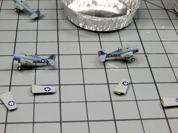
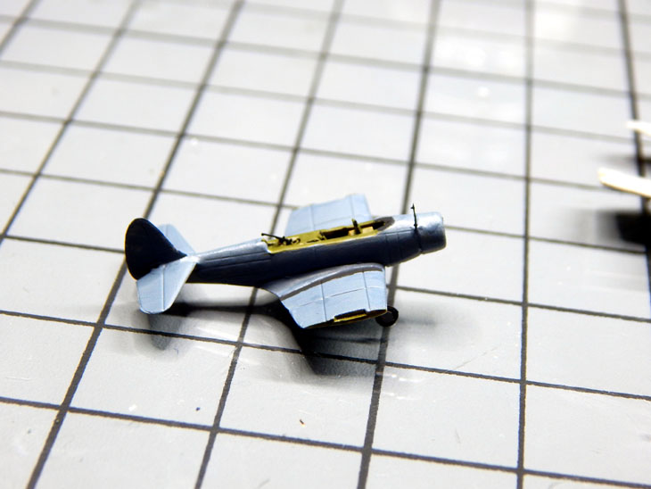
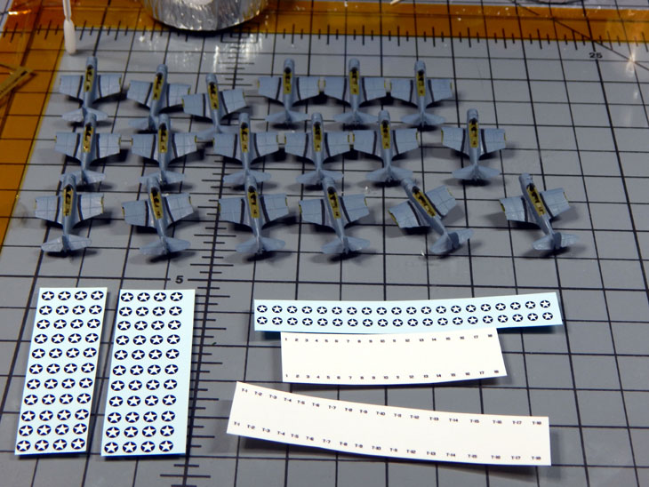
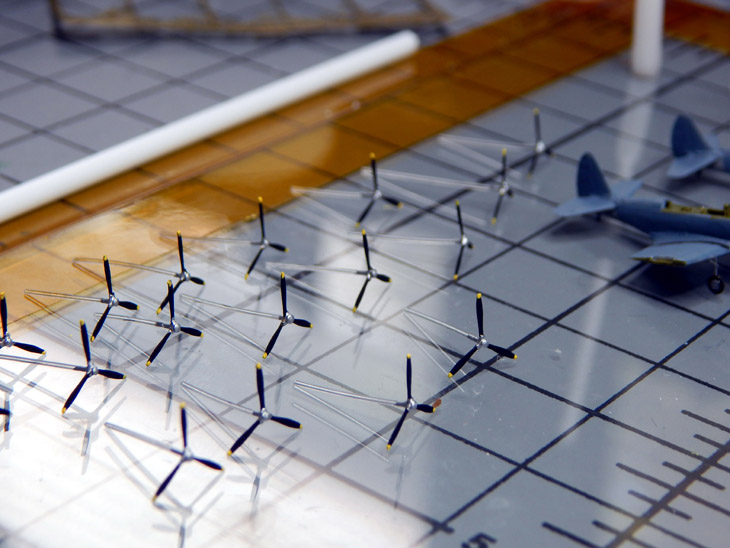
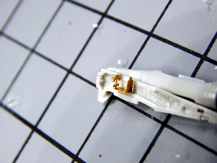
It has been another week of work on the USS Hornet CV-8 aircraft. I am still working on the F4F Wildcats. For this week I am showing all the little bits of Photo etch and the process of adding them to the aircraft. Once the fuselage is assembled I added the main gear which consists of the main strut, the landing gear doors, two struts, and a tail wheel. The main strut is added first then the doors. Getting the struts in position using very fine tweezers then gluing in place takes a little time. I find the Glue Looper V4 tip works very well for placing two very small spots of glue on the fuselage and main gear. Once dry I then place the tires and outside hubs on. I pre-painted the parts but they will require touch up after bending and gluing them. I then added the tail wheel. There is a slot for the kit tail wheel so the photo etch version fits into and using medium viscosity CA glue it fills the gap on each side since the photo etch part is a lot thinner than the kit tail wheel. After it dries I then do paint touch ups and paint the underside grey. While the landing gear dries, I assemble the propellers. I included a photo of the assembly showing the fiber optic with the hub and propeller separated to show the process. There is a total of 18 F4F’s that are being built. I am hoping to finish them next week so I can start on the others.
See more photos and details from the start in my build log at https://davidsscalemodels.com/build-log/1-350-uss-hornet-cv-8-doolittle-raid/


See more photos and details from the start in my build log at https://davidsscalemodels.com/build-log/1-350-uss-hornet-cv-8-doolittle-raid/
What I enjoy most is seeing what others are doing so I can try what they show in the pics.It has been another week of work on the USS Hornet CV-8 aircraft. I am still working on the F4F Wildcats. For this week I am showing all the little bits of Photo etch and the process of adding them to the aircraft. Once the fuselage is assembled I added the main gear which consists of the main strut, the landing gear doors, two struts, and a tail wheel. The main strut is added first then the doors. Getting the struts in position using very fine tweezers then gluing in place takes a little time. I find the Glue Looper V4 tip works very well for placing two very small spots of glue on the fuselage and main gear. Once dry I then place the tires and outside hubs on. I pre-painted the parts but they will require touch up after bending and gluing them. I then added the tail wheel. There is a slot for the kit tail wheel so the photo etch version fits into and using medium viscosity CA glue it fills the gap on each side since the photo etch part is a lot thinner than the kit tail wheel. After it dries I then do paint touch ups and paint the underside grey. While the landing gear dries, I assemble the propellers. I included a photo of the assembly showing the fiber optic with the hub and propeller separated to show the process. There is a total of 18 F4F’s that are being built. I am hoping to finish them next week so I can start on the others.
See more photos and details from the start in my build log at https://davidsscalemodels.com/build-log/1-350-uss-hornet-cv-8-doolittle-raid/
Progress this week is going slowly on the Trumpeter 1/350 USS Hornet build. All things being equal 1/350 modern jets are much easier to build than World War II fighters. With the landing gear finished I needed to install the antennas. Using the Glue Looper V4 and a Pic-N-Stic I was able to place a small drop of CA glue and CAREFULLY place the antenna.
( Check out the Tips and Tricks section for the items I used at https://davidsscalemodels.com/tips-and-tricks/photo-etch-tools/ )
It may look easy but it took one evening just to install them on 18 aircraft. With all the photo etch added I painted all the aircraft and their wings. With the wings being in the folded position I needed to put the decals on before the wings. I had purchased the Starfighter Decals Hornet Air Wing decal set. I am not sure if it was the decal film was too thin or somehow they got degraded but the squadron numbers and the aircraft numbers on the cowl were very difficult to slide and place. They kept falling apart and cracking. After messing up many of them I decided to just make my own numbers. I printed out a set for all the squadrons and replaced the ones that messed up with my own. With the decals all placed I added the canopy, wings and propeller. So the first F4F is done, only 17 more to go! Once these are finished I will be starting on the Devistator torpedo aircraft.
See more photos and details from the start in my build log at https://davidsscalemodels.com/build-log/1-350-uss-hornet-cv-8-doolittle-raid/
Enjoying seeing the ship come together. My daddy was a torpedoman-gunner on an aircraft carrier. My friend's dad was on Enterprise so that is my connection.
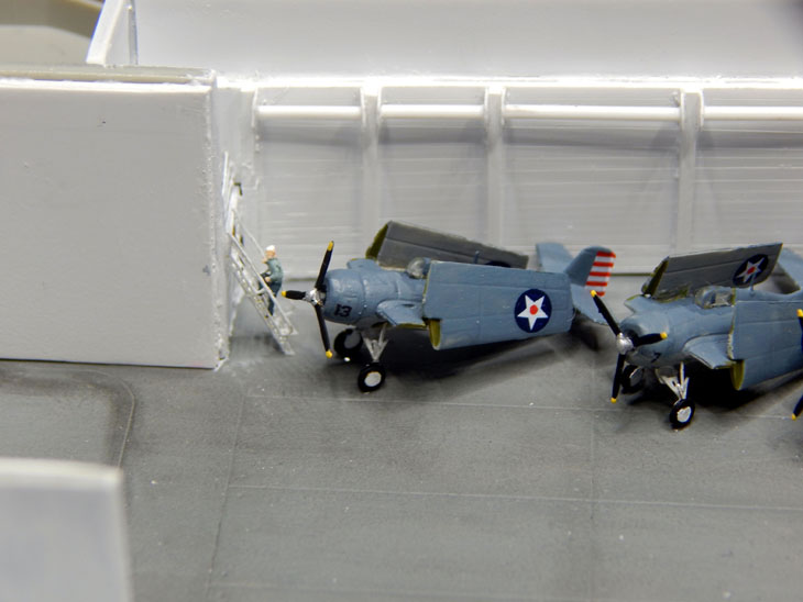
The F4F Wildcats of “Fighting 8” for the USS Hornet are completed and aboard! I set up an assembly line. First I placed all the decals on the wings and lined them up. The decals were then applied on the fuselage. While they were drying I grabbed one of the 3-D printed Moto-Tugs from BaconFist on Shapeways and painted one of them. The detail for such a small tractor is awesome. The engine was painted engine gray. The body was painted intermediate blue with a black dash and seat. I also painted the front grill openings and tires. Once the Wildcats were completed I placed them in the aft hangar bay. I will set them in place later when I add the figures. I am finally starting the Devastators for “Torpedo 8” today.
See more photos and details from the start in my build log at https://davidsscalemodels.com/build-log/1-350-uss-hornet-cv-8-doolittle-raid/


See more photos and details from the start in my build log at https://davidsscalemodels.com/build-log/1-350-uss-hornet-cv-8-doolittle-raid/
Its the attention to detail which sets this build apart.The F4F Wildcats of “Fighting 8” for the USS Hornet are completed and aboard! I set up an assembly line. First I placed all the decals on the wings and lined them up. The decals were then applied on the fuselage. While they were drying I grabbed one of the 3-D printed Moto-Tugs from BaconFist on Shapeways and painted one of them. The detail for such a small tractor is awesome. The engine was painted engine gray. The body was painted intermediate blue with a black dash and seat. I also painted the front grill openings and tires. Once the Wildcats were completed I placed them in the aft hangar bay. I will set them in place later when I add the figures. I am finally starting the Devastators for “Torpedo 8” today.
See more photos and details from the start in my build log at https://davidsscalemodels.com/build-log/1-350-uss-hornet-cv-8-doolittle-raid/
This week I started working on the Devastators for Torpedo 8 for the USS Hornet. I am using White Ensign’s cockpit detail set #3548 and Tom’s Modelworks aircraft detail set #3538. The cockpit fits very well. I plan on having some of the aircraft with the canopy open and some with the canopy closed. Just like the Wildcats I set up an assembly line. Mounting the cockpit and seats first then assembling the fuselage. The detail set includes the rear gun, antenna, and the gun sight. One thing to note, The instructions for the aircraft assembly show the wings folded pointing straight up when in reality they fold over. Next I will be starting to paint the fuselage section and wings in preparation for the decals.
See more photos and details from the start in my build log at https://davidsscalemodels.com/build-log/1-350-uss-hornet-cv-8-doolittle-raid/


See more photos and details from the start in my build log at https://davidsscalemodels.com/build-log/1-350-uss-hornet-cv-8-doolittle-raid/
The Devastators for Torpedo 8 are almost finished. I added the landing gear and wheels. The landing gear required some tedious work to get them to line up together. There are 3 attachment points so getting the left side and right side to line up as well as stand straight from the front took a lot of work. The landing gear struts were then painted aluminum, tire black for the tire and then the medium grey for the hubs and underside of the aircraft. The top was painted intermediate blue. The wings required a lot of work as well as they had a lot of flash. Especially on the trailing edge which is also very thin. Once finished they were painted. I then looked at the decals. The ones that came with the Trumpeter kit had the incorrect blue for the insignias so I will be using the Starfighter decals. This morning I was going to start applying the decals however, I was looking at some reference photos and noticed the antenna is incorrect. The one photo from the side looked like the antenna was offset similar to the vindicator and dauntless. It turns out the antenna on the devastator is actually just behind the cowl and centered. So I need to correct that today. Once I correct them I can start the decals. Hoping to finish the Devastator’s during this nice long Labor Day weekend then start on the Dauntless dive bombers of Bombing 8.
See more photos and details from the start in my build log at https://davidsscalemodels.com/build-log/1-350-uss-hornet-cv-8-doolittle-raid/


See more photos and details from the start in my build log at https://davidsscalemodels.com/build-log/1-350-uss-hornet-cv-8-doolittle-raid/

The TBD’s of Torpedo 8 for the 1/350 Trumpeter USS Hornet are finished. After I spent an evening correcting the misplaced antenna the canopies were added and then I applied all the decals to the fuselage and then the wings were painted and decaled. The wings were carefully placed in the folded position. With the aircraft drying from adding wings and decals I painted all the propellers and trimmed them to mount onto the aircraft. Once dry all the propellers were added to complete the aircraft. They were all staged on the hangar deck.
I then started on the SBD Dauntless dive bombers of Bombing 8. The fuselage required some trimming for the cockpit section to fit. I then grabbed some reference photos. The reference photos show that some aircraft have the dive brakes open and some closed. I will do the same with some open and some closed. I also realized that the SBD Dauntless is missing one thing that most Navy aircraft have, folding wings! So once I get these all built I will need to figure out how to get all these aircraft on the hangar deck. Anyhow, getting back to the build, the cockpit photo etch has a tub with a seat and an instrument panel with pedals. There is also the rear gunner seat, gun mount, and gun which needs to be placed after the fuselage is together. I also have the photo etch set that includes the bomb swing and the dive brakes. I will be using the photo etch dive brakes on a few of them. I am working on setting up the assembly line for them now.
See more photos and details from the start in my build log at https://davidsscalemodels.com/build-log/1-350-uss-hornet-cv-8-doolittle-raid/
The SBD’s of Bombing 8 are getting closer to being completed. I made one of them with canopy open and dive brakes open. There will be two more with just the rear gunner canopy open and the rest will be all closed. I had to fill in the hole for the tail wheel so I could mount the photo etch version. Another thing I am doing is since the SBD’s do not have folding wings some of the aircraft on the ship had their wings, bomb swing, and propeller removed then the fuselage was hung in the rafters of the hangar bays. So there will be a wing rack as well as a rack for holding the propellers as well as spare propellers for the aircraft. I also found some reference photos of how the aircraft were arranged in the hangar bay. The very few photos I found show the F4F Wildcats forward, TBD’s mid-ship, and the SBD’s aft. So once the SBD’s are finished I will map out where the aircraft will be placed on the hangar deck.
The photo etch set also has bomb carts and torpedo carts which will be added to the hangar near the weapons elevator. I bought some brass early MK 13 torpedoes to place on the torpedo carts. I am hoping to start working on the hangar deck details and crew next week. Still need to figure out the routing for the fiber optics to illuminate the hangar deck as well.
See more photos and details from the start in my build log at https://davidsscalemodels.com/build-log/1-350-uss-hornet-cv-8-doolittle-raid/
The SBD’s of Bombing 8 for the USS Hornet have been completed! I completed the detail painting then applied all he decals then attached the propellers. I scratch built a rack to hold the propellers and added a bunch of them on the rack. I then started squeezing all the aircraft on the hangar deck. I added a couple more moto-tugs and placed the torpedo and bomb carts near the weapons elevator. I then laid out all the under deck girders. At first I tried using CA glue but with the size and length of the assembly then kept breaking loose. So I decided to solder them together. This worked a lot better. I made two assemblies. The assemblies are separated by the mid-ship elevator. I taped everything into place an measured the room available. There is a lot less room than I originally thought. I would need about 0.6mm of space but I only have about 0.15mm of space. This coupled with the thickness of the hangar walls it looks like I will not be able to add the fiber optic lines for each light.
There is just no room for the estimated 14 feet of fiber optic lines. So I will be moving on to plan B. Instead of fiber optic lighting I am just going to use Nano sized LED’s. These will be placed in the girders throughout the hangar deck.
With the girder assemblies built, I need to attach the aircraft and other details into the hangar deck. One of the things I need is the crew. So I will start off with the accessories I bought. I have a set of Eduard photo etch crew figures that I bought a few years ago when I was getting accessories for a different project. I ended up not using them back then. For this project I bought the Tamiya crew set which has 144 figures in 6 different poses. I also purchased 120 3-D printed crew figures. These were bought on Shapeways by member Holder8702 on his Panzer vs. Tanks page. The Tamiya crew members will be used mostly on the hangar deck and the 3-D printed will mostly be on the flight deck and island. I will not be using the Eduard set. The photo etch came painted but they are too thin to look real. The Tamiya figures are thicker but only have basic details See the photo below where I compare a saluting crew member between all 3 sets. I have lots of fine detail painting and mapping out where they will be placed to get accomplished before I can move on to the lighting.
See more photos and details from the start in my build log at https://davidsscalemodels.com/build-log/1-350-uss-hornet-cv-8-doolittle-raid/
This week on the USS Hornet project I was able to paint many figures and get them placed around the hangar deck. I used mostly the Tamiya figures with a few of the 3-D printed figures. One of the 3-D printed figures was in a seated position so he is now driving a Moto-tug. Another was kneeling so he is working on a dauntless SBD’s dive brakes. The last one I used was one posed walking up a ladder. The rest of the 3-D printed will populate the flight deck and island. With figures placed, I paced all the aircraft back in the hangar and added a few more figures, more moto-tugs, and the weapons carts near the weapons elevator. I then installed the aft girder assembly. This has turned into a slow process. One side needs to be attached and cured before attaching the other side. This is needed to keep the girders straight. I then placed some of the SBD’s in the girders.
With the girders in place I started mapping out where the lighting will go and how to route the wiring for the aft section of the hangar for illumination. I am currently working on the forward section of girders now.
See more photos and details from the start in my build log at https://davidsscalemodels.com/build-log/1-350-uss-hornet-cv-8-doolittle-raid/
And we still complain about such an activity as weaving scraps on a sailboat. Try to collect as many identical planes and place them on this ship, taking into account the scale of the model. Your work looks amazing.
Those planes look very realistic considering the size. Great details !!!
So, I have a question and I am going to put full display of my ignorance of the subject of photo etch parts.
1. I assume the reason for the PE parts is because the plastic parts are not good enough?
2. the PE parts are an "addition" to the model that the kit does not supply?
. . . and other reasons ?
I ask because one of these days, I am going to try and tackle a 'Carrier' that has the PE kits that I will purchase separately from a variety of manufactures. But, before I do that - this begs the question to my own self as to why? I am not asking why as in a negative manner, I am just asking to get a better understanding of the use of PE parts. This is all new territory for me. I also assume that when following the installation of the PE parts, that they would have instructions as to where the part is going and also what plastic part it is replacing, etc.
Lastly, I have seen PE parts painted the same color as ship and also I have seen the brass parts left as is without painting.
The PE parts add details not normally on plastic kits like railings or stairs. They also include fine details like realistic antenna's or cockpits on 1/350 aircraft. Many times a plastic part is thicker and has less details than a PE part or the plastic part lacks details like doors and hatches. Since you mentioned carriers, There are may areas like the safety net that goes around the flight deck of modern carriers. The plastic of the kit has them thick and solid where the PE version is thin and you can see thru the "netting". Here is a close up of railing, stairs, and added doors I did on my Vinson build (prior to painting)Those planes look very realistic considering the size. Great details !!!
So, I have a question and I am going to put full display of my ignorance of the subject of photo etch parts.
1. I assume the reason for the PE parts is because the plastic parts are not good enough?
2. the PE parts are an "addition" to the model that the kit does not supply?
. . . and other reasons ?
I ask because one of these days, I am going to try and tackle a 'Carrier' that has the PE kits that I will purchase separately from a variety of manufactures. But, before I do that - this begs the question to my own self as to why? I am not asking why as in a negative manner, I am just asking to get a better understanding of the use of PE parts. This is all new territory for me. I also assume that when following the installation of the PE parts, that they would have instructions as to where the part is going and also what plastic part it is replacing, etc.
Lastly, I have seen PE parts painted the same color as ship and also I have seen the brass parts left as is without painting.

You can see all the build photos on my Vinson Project at https://davidsscalemodels.com/build-log/1-350-uss-carl-vinson/
This was my USS Missouri built where you can see what the kit turrets look like and what they look like after PE details are added https://davidsscalemodels.com/build-log/1-350-uss-missouri-bb-63-wwii/
Finally, here are the tools I use to attach PE parts https://davidsscalemodels.com/tips-and-tricks/photo-etch-tools/
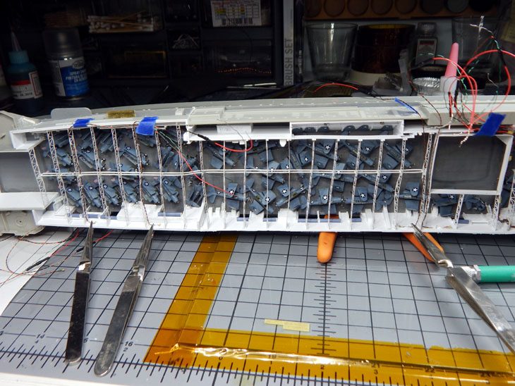
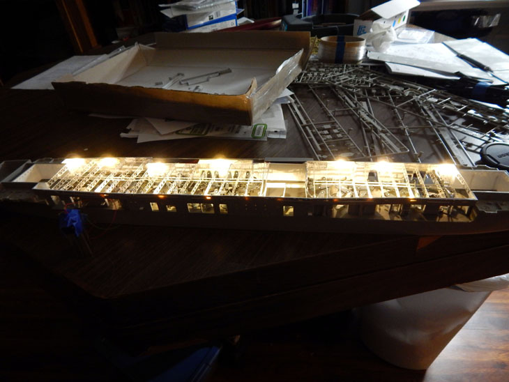
This is week 15 on the USS Hornet project. I spent most of the week figuring out the light placement and how to route all the wiring. Looks like I will be running a total of 18 LED’s for the hangar deck. For the section between the rear elevator to the mid-ship elevator I have 8 of the NANO size LED’s. These are the “Warm White” color. Placing them on alternate sides and staggering them gives me the best effect. Placing the LED’s is a slow process. I first started by placing the LED into the location and attaching it using acrylic gel. Once the gel is cured I then route the wire and use the gel to hold the in place.
When you look at the photos don’t worry about the girders being bent/warped. Feeding the LED’s and routing the wire causes them to distort as they are handled while feeding the wires and LED’s thru them. I am going to wait until I am ready to install the flight deck before I straighten them. The wires are being routed to the section under the island. Later I will join these with the wiring from the island and run the wires into the bottom of the hull.
Since it takes time for the gel to cure, I stated looking at the island. Since I plan on lighting it as well I drilled out all the port holes and windows on the on it. For the square widow I used a square file. It looks like the bridge has two sections so I will need 2 NANO LED’s. I then need to figure out which LED’s and where to place them inside the main part of the island to give even lighting thru all the port holes. The last of the hangar LED’s are curing now. I then need to do some painting and touch-ups on the wiring to blend them with the hangar deck. Once that is done, I then need to look at the flight deck and prepare it for the wooden flight deck. This will be the first time I will be doing a wooden deck on a model.
See more photos and details from the start in my build log at https://davidsscalemodels.com/build-log/1-350-uss-hornet-cv-8-doolittle-raid/
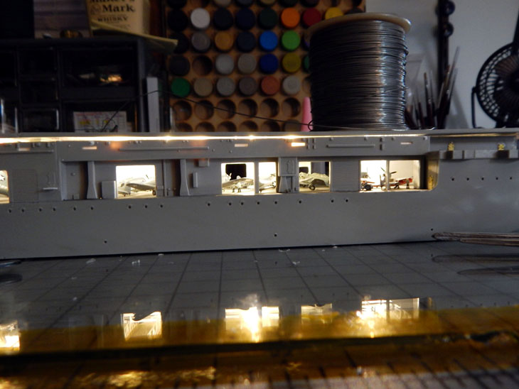
Moving right along for week 16 of the USS Hornet project I have finished installing the hangar deck lights. To get the effect of multiple lights I staggered them from each side. All the wiring was routed to the section under the island so the wiring can be run to the bottom of the hull. With the hangar deck finished I started working on the island.
I first drilled out all the portholes and windows. The windows on the bridge were then filled with acrylic gel to simulate the glass. The bridge is divided into two sections so I used two PICO sized LED’s to light it up. The rest of the island is illuminated with two 5mm LED’s. I then drilled out the funnel caps and replaced them with the photo etch details.
Over the next week I will be detailing the island so I can install it on the flight deck as one assembly. This is needed so I can run the wiring into the hull.
See more photos and details from the start in my build log at https://davidsscalemodels.com/build-log/1-350-uss-hornet-cv-8-doolittle-raid/