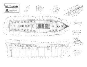
This build is dedicated to Geoff Wilson Aussie48
Ahoy Shipmates,
I bought this model three years ago and never started because I was too afraid of making a mess of the planking. Now hear I am bashing this kit like, OK, what's next.
With the help of Capt. Mike41we intend to make this plank on bulkhead model a Plank on Frame memorial to a great Shipmate.
Enough sweet talk he Hardys, on with the build log.
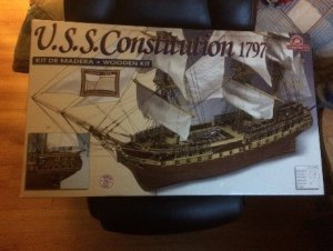
USS Constitution was one of six frigates authorized for construction by an act of Congress in 1794. Joshua Humphreys designed them to be the Navy's capital ships. Larger and more heavily armed than the standard run of frigate, Constitution and her sisters were formidable opponents even for some ships of the line.
U.S.S. Constitution (Old Iron Sides)
Description
Three-masted, sailing wooden warship of the frigate class rated to carry 44 guns. One of the six frigates authorized in 1794 to form the new United States Navy.
General Characteristics
Primary Function:
USS Constitution is the oldest commissioned warship afloat in the world. Nicknamed Old Ironsides in the War of 1812, USS Constitution is interpreted today to the 1812 era.
Builder:
Col. George Claghorne, Edmund Hartt's Shipyard, Boston, MA
Date Deployed:
Launch Date: October 21, 1797; First Sail Date: July 22, 1798
Unit Cost:
$302,718 (1797 dollars).
Propulsion:
1812 Propulsion: 48 sails , over 44,000 square feet of sail, equal to over 1 acre of canvas
Length:
length overall 305 feet (93 meters); 207 feet (63.1 meters), billet head to taffrail; 175 feet at waterline (53.3 meters)
Height:
Main mast, from the spar (upper) deck to the top of the mast, is 172 feet (54.4 meters) today
Beam:
43.5 feet (13.3 meters)
Displacement:
1,900+ tons
Draft:
1812 Draft: 24 feet aft, when fully loaded (7.3 meters); Draft Today: 22.5 feet aft (6.9 meters)
Speed:
1812 Speed: 13+ knots (approx. 15 miles per hour, 24 km. per hour)
Crew:
1812 Crew: 450 including 55 Marines and 30 boys (1797); Crew Today: 3 officers, 85+ enlisted U.S. Navy men and women
Armament:
1812 Armament: Spar Deck: 24, 32-pound carronades, 4 - 8 man crew, range of fire approx. 400 yards;
1, 18-pound bow chaser; Gun Deck: 30, 24-pound long guns, 7-14 man crew, range of fire approx. 1,200 yards
Landing/Attack Craft:
1812 Boats: Used for transporting officers and crew between ship and shore for communication purposes, landing parties, transporting goods and services for the ship, and shore leave.
-36ft Launch (1)
-28ft whaleboat (2)
-27ft and 28ft cutters (4)
-Gig (1)
Homeport:
Charlestown Navy Yard, Boston National Historical Park
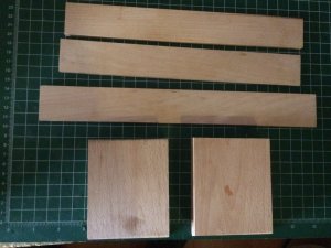
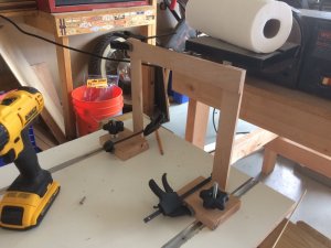
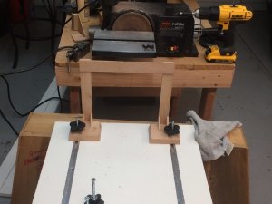
One of the things Geoff liked about SOS was the friendliness of the members of this club and of how everyone is ready to help if they can. I said at first I was stopping all my other projects and devoting all my time to "Connie" until she is finished. One project I was working on was a Gantry ship-way build system.
Capt Mike Shared his build system with the club a while back and I thought I would build one.
I went to Home Depot ready to pay for an 8 x 4 foot piece of Melamine board at $30 + per board. The friendly Salesman at Home Depot hooked me up with a piece that required one cut to fit my needs.
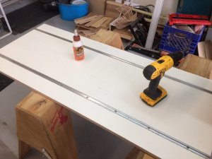
Armed with a piece of melamine board 48" x 20" I found a carpentry Shop that turned out to be a Carpentry School. They happily put the perfectly spaced router cuts 6 inches from center-line.
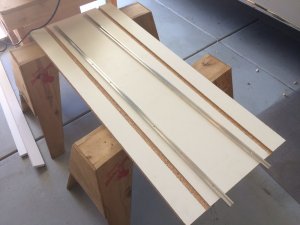
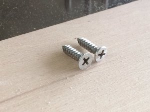
I then glued two T-tracks in and secured them with wood screws.
That's all I have for now. More to follow.


Ahoy Shipmates,
I bought this model three years ago and never started because I was too afraid of making a mess of the planking. Now hear I am bashing this kit like, OK, what's next.
With the help of Capt. Mike41we intend to make this plank on bulkhead model a Plank on Frame memorial to a great Shipmate.
Enough sweet talk he Hardys, on with the build log.

USS Constitution was one of six frigates authorized for construction by an act of Congress in 1794. Joshua Humphreys designed them to be the Navy's capital ships. Larger and more heavily armed than the standard run of frigate, Constitution and her sisters were formidable opponents even for some ships of the line.
U.S.S. Constitution (Old Iron Sides)
Description
Three-masted, sailing wooden warship of the frigate class rated to carry 44 guns. One of the six frigates authorized in 1794 to form the new United States Navy.
General Characteristics
Primary Function:
USS Constitution is the oldest commissioned warship afloat in the world. Nicknamed Old Ironsides in the War of 1812, USS Constitution is interpreted today to the 1812 era.
Builder:
Col. George Claghorne, Edmund Hartt's Shipyard, Boston, MA
Date Deployed:
Launch Date: October 21, 1797; First Sail Date: July 22, 1798
Unit Cost:
$302,718 (1797 dollars).
Propulsion:
1812 Propulsion: 48 sails , over 44,000 square feet of sail, equal to over 1 acre of canvas
Length:
length overall 305 feet (93 meters); 207 feet (63.1 meters), billet head to taffrail; 175 feet at waterline (53.3 meters)
Height:
Main mast, from the spar (upper) deck to the top of the mast, is 172 feet (54.4 meters) today
Beam:
43.5 feet (13.3 meters)
Displacement:
1,900+ tons
Draft:
1812 Draft: 24 feet aft, when fully loaded (7.3 meters); Draft Today: 22.5 feet aft (6.9 meters)
Speed:
1812 Speed: 13+ knots (approx. 15 miles per hour, 24 km. per hour)
Crew:
1812 Crew: 450 including 55 Marines and 30 boys (1797); Crew Today: 3 officers, 85+ enlisted U.S. Navy men and women
Armament:
1812 Armament: Spar Deck: 24, 32-pound carronades, 4 - 8 man crew, range of fire approx. 400 yards;
1, 18-pound bow chaser; Gun Deck: 30, 24-pound long guns, 7-14 man crew, range of fire approx. 1,200 yards
Landing/Attack Craft:
1812 Boats: Used for transporting officers and crew between ship and shore for communication purposes, landing parties, transporting goods and services for the ship, and shore leave.
-36ft Launch (1)
-28ft whaleboat (2)
-27ft and 28ft cutters (4)
-Gig (1)
Homeport:
Charlestown Navy Yard, Boston National Historical Park
One of the things Geoff liked about SOS was the friendliness of the members of this club and of how everyone is ready to help if they can. I said at first I was stopping all my other projects and devoting all my time to "Connie" until she is finished. One project I was working on was a Gantry ship-way build system.
Capt Mike Shared his build system with the club a while back and I thought I would build one.
I went to Home Depot ready to pay for an 8 x 4 foot piece of Melamine board at $30 + per board. The friendly Salesman at Home Depot hooked me up with a piece that required one cut to fit my needs.
Armed with a piece of melamine board 48" x 20" I found a carpentry Shop that turned out to be a Carpentry School. They happily put the perfectly spaced router cuts 6 inches from center-line.

I then glued two T-tracks in and secured them with wood screws.


That's all I have for now. More to follow.


Last edited by a moderator:


