• LUCZORAMA SHIPWRECK SCAVENGER HUNT GIVEAWAY. 4 Weeks of Fun • 1 Legendary Prize ((OcCre’s Fram Ship)) • Global Crew Welcome!
    **VIEW THREAD HERE**

Unimat Hobby Lathe Restoration

Kurt Konrath

Kurt Konrath
Joined
Feb 11, 2020
Messages
4,999
Points
588

Location
Oklahoma City OK
Well I have been encouraged to post a "cleaning and restoring" log of the Unimat, that I recently bought from a fellow member of SoS.

Yesterday I received the unit from him thru my local shop that I have UPS things delivered to, and got a chance to give it a once over for what needed to be done to get it operational for use.

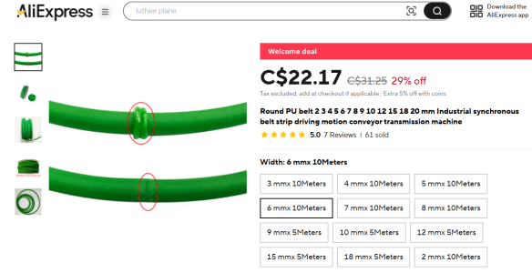
I had been told it had no belts, and I found a good online source to order a set of belts and other items that will be useful in operations.

After a trip to few local stores to get supplies needed, I am about ready to start on this project which should take only a few days to complete.
 
OK, for those who don't know what a Unimat Multipurpose Lathe is, here is some generic info I found online from one vender.

The Unimat DB/Sl model was first introduced here ( North America ) in the mid 1950's by Emco .This precision miniature Table Top Machining Lathe/Mill was made in Austria and sold world wide in the hundreds of thousands until production ceased in 1977. It's replacement the Unimat-3 was made between 1976 and 1990. These wonderful little machines are now orphans since Emco discontinued support of accessories, parts and manuals.
The uses of these machines are as unlimited as the skill and imagination of the operator given the wealth of accessories available.
There is resurgent interest in the Unimat here in the U.S. and the secondary market reflects that, as prices for machines and accessories are on the rise. Machines are brought down from storage shelves, rescued from boxes in the basement, bought at flea markets, they trade hands on the Internet and are brought back to life as new generations discover the enjoyment their fathers found working with their hands .
These machines have gone through some changes during the length of production, I will go over them briefly as they are documented on other sites. The machines have not changed in basic design or overall appearance. The first DB's were cast iron and painted hammertone silver with two styles of motors, the early one was silver with a switch at the bottom, the later motor was a gray/black Dutch manufacture motor, with hand wheels more detailed with waisted handles. The later production DB's/ SL's were of cast aluminum-zink ( white metal ) and painted hammertone green, the handles on the hand wheels were now a straight ta per, there was a change in the mill mast and socket design. The early units in this production had a green metal cased motor with exposed brush access. The next change, that came sometime in the 70's, was the U-100 motor of gray plastic with an orange built-in slide switch, this motor was internally fan cooled and continuously rated ( probably their best motor ). In the final years of production the green steel cased motor returned and the hand wheels were now made of plastic. From what I have read, I believe over 400,000 units were produced.
Please keep in mind that: these features overlapped in production cycles, I am not a Unimat expert, any Unimat information, additions or corrections that you would like to share I would gladly post here. Note: In General the Unimat DB, DB200, SL, SL1000 parts & access. are interchangeable.
 
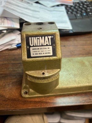
So my unit is the Unimat SL 1000 designation, not sure what is different between that and the DB 200. I have the older U90 110volt AC motor that came with it.

Also in the box were several nice attachments, which are hard to find now a days, and if available are costly on the web or Evil Bay!

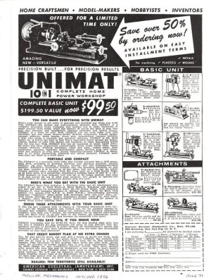
Units which sold for under $200 with lots of stuff in the 60's are now selling for well over $500-$1,500 online. Many units showing up like the one I got are old barn finds, or from clean out of shops when owner moved or passed away. Lots of those I have seen online for sale are "rust buckets" which would take lots of restoration, but the one I got was mostly just used oil, and dust packed from 15 years of collecting from the air around it.

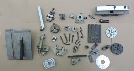
I got the Table Saw attachment, Planning attachment, and it came with the Power Feed attachment installed. Some extra parts included an arbor for holding wood stock for turning, and the large wood turning support, a steady rest, to help hold long items steady, and an indexing attachment, used to control rotating an item for milling such as cutting gears. It had the 3x5ish milling table and multiple bolts and clamps to help hold things down. Also was standard faceplate and lathe dog, used for metal turning, and a "Jacobs Chuck" which is like a big drill head, and the old 3-jaw chuck. Plus a bunch of odds and end screws that are all part of the accessories.
 
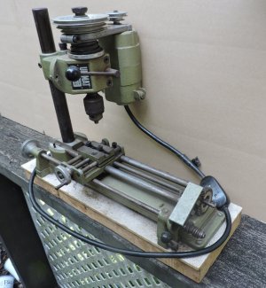
OK, so my unit was offered for sale here on SoS, and here are photos of what was offered, and an add page, another member posted for reference and cost comparisons.

In this photo, the unit is configured as a vertical milling machine. The headstock and motor assembly detach from angled adapter and it and the post are removed and headstock placed in horizontal mode for standard lathe functions.


SL 1000  Parts.jpgSL 1000 Vertical Setup.jpgUnimat Add.jpg
 
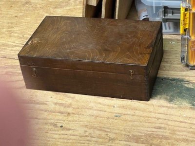
The unit was disassembled from shown photo for for shipping, and I got a box with the base assembly mounted on a 2x6 with plastic top to help with cleaning underneath. The manual recommends it be mounted to solid base to help keep if from tipping over as the motor weights as much as base. There were several other items all well wrapped in lots of bubble wrap and then the good old box full of the small items.

You will have to excuse my dirty cluttered back drop, as most of these were taken while sitting at my shop computer desk, stacked with tools and other hobby projects.


box overview.jpgSL 1000 Mounted.jpg
 
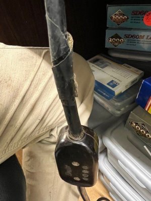
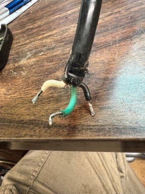
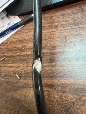
OK, first the easy part was seeing what I could do with the noticeable issue with the power cord for the motor, which had a spot loosely wrapped in electrical tape.

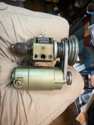
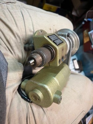
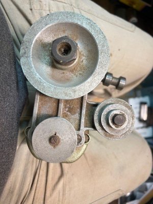
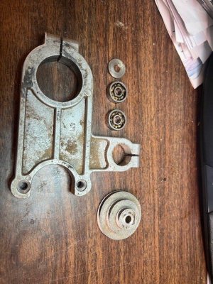
First steps were to remove pully from the motor attachment bracket, which has two screws behind it that hold the motor on, the pully is held on with a single screw and the pulley in on a keyed shaft. A few taps with light hammer and the pulley came off with no issues, and it and screws went into my parts bin for inspection and cleaning. I then pulled the pully off the headstock by removing the jam nut, which also acts as drive pulley for power feed attachment. After that was removed, I loosened the Allan screw and popped bracket off the spindle.

Then I gave the motor a wipe down with paper towels and light brush to remove dust and oil residue. So you can see the headstock and motor assembly which has an idler pulley as part of bracket. After taking the major parts off, I removed the idler pulley which is held by a bolt and has two small ball bearings for the pulley to run on.


headstock and motor top.jpgheadstock and motor.jpgmotor bracket and pulleys.jpgmotor mount bracket.jpg

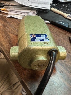
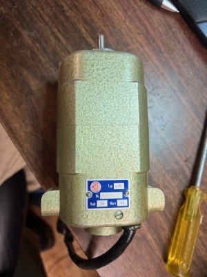
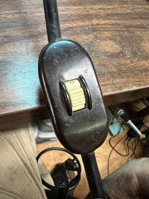
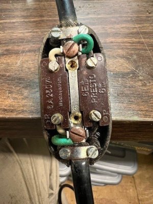
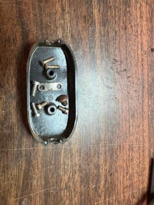
Next up was inspection of power cord damage, and what I could do to repair or replace it. At first thought I was going to just replace the cord and switch with longer newer cord, but that would involve opening the motor up which I didn't want to do, so I looked at damage and then the switch. As luck would have it the switch back came off and showed a simple three wire mount to end of switch body, which I removed to expose the end of power cord, and this is about two inches from damaged spot, which looked like a rat had for lunch, and I should be able to just shorten the cord and resolder the ends and install back in switch to make as good as new, with no repairs visible.

U90 Motor.jpgMotor top.jpgpower cord issue.jpgPower switch.jpgswitch inside back.jpgswitch parts.jpgEnd of power cord.jpgcord damage.jpg

This should be a short simple repair based on design of the internal switch with mounts for the three wires on each end, I was worried it would be type where ground and neutral wires ran straight thru and only the hot wire was effected by the switch.
 
OK, next up is disassembly of the headstock unit and spindle assembly, I started this when I pulled the large drive pulley off for removing the motor mount bracket, as the back of pulley is the cover for outer bearings. One thing to mention when taking off the motor bracket, is to first loosen the spindle lock and allow the spring unit on outboard end to decompress, I didn't do this and I had parts flying around when the spring kicked back as I loosed the allen screw on the bracket.

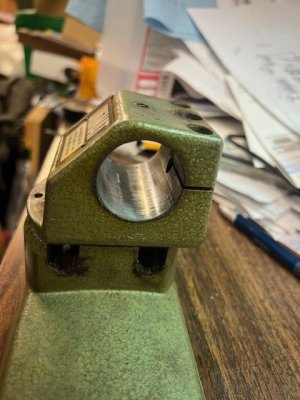
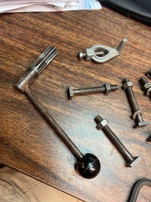
After removing the bracket for motor mount, and the tension spring, which not all units have installed, it allows for spring load when using the headstock as mill or drill, as the spindle has a few inches of travel when quill handle is installed and the spindle is unlocked. It then works like a drill press.

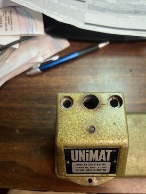
On top of the headstock are two lock screws and a allen screw which keeps the spindle from rotating, they need to be removed. The large center hole is for the quill handle to be inserted when needed. FYI most all screws, nuts and bolts are metric as these units were made in Austria.

Once the pully, bracket and spring have been removed and top hardware is removed the spindle unit can slide out of the headstock.

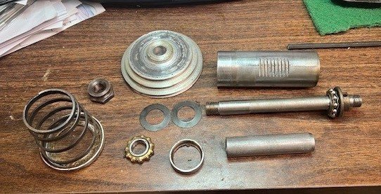
The standard spindle will self disassemble, aka fall apart after pulley is removed, and there is an outer bearing that comes out, a inner race and two preloaded tension spring washers inside, as well as a bearing spacer tube. With these removed from the spindle body, the main shaft comes out the right side, if it hasn't fallen out already. You want to remove any attachment on the end of the spindle for cleaning and reassembly. I show the headstock and spindle disassembled and have to check bearings to see if they just need cleaning or replacement.

You can see by looking at spindle that it has groves that mate with the quill handle for advancing or moving it as needed.headstock face.jpgheadstock side.jpgheadstock top.jpgQuill Lever and bolts.jpgspindle parts.jpg
 
H
OK, first the easy part was seeing what I could do with the noticeable issue with the power cord for the motor, which had a spot loosely wrapped in electrical tape.

First steps were to remove pully from the motor attachment bracket, which has two screws behind it that hold the motor on, the pully is held on with a single screw and the pulley in on a keyed shaft. A few taps with light hammer and the pulley came off with no issues, and it and screws went into my parts bin for inspection and cleaning. I then pulled the pully off the headstock by removing the jam nut, which also acts as drive pulley for power feed attachment. After that was removed, I loosened the Allan screw and popped bracket off the spindle.

Then I gave the motor a wipe down with paper towels and light brush to remove dust and oil residue. So you can see the headstock and motor assembly which has an idler pulley as part of bracket. After taking the major parts off, I removed the idler pulley which is held by a bolt and has two small ball bearings for the pulley to run on.


View attachment 533978View attachment 533979View attachment 533980View attachment 533981

Next up was inspection of power cord damage, and what I could do to repair or replace it. At first thought I was going to just replace the cord and switch with longer newer cord, but that would involve opening the motor up which I didn't want to do, so I looked at damage and then the switch. As luck would have it the switch back came off and showed a simple three wire mount to end of switch body, which I removed to expose the end of power cord, and this is about two inches from damaged spot, which looked like a rat had for lunch, and I should be able to just shorten the cord and resolder the ends and install back in switch to make as good as new, with no repairs visible.

View attachment 533991View attachment 533986View attachment 533987View attachment 533988View attachment 533989View attachment 533990View attachment 533985View attachment 533984

This should be a short simple repair based on design of the internal switch with mounts for the three wires on each end, I was worried it would be type where ground and neutral wires ran straight thru and only the hot wire was effected by the switch.
Hi Kurt,

Well done on your purchase, once cleaned up it should give you hours of good service.

I would like to suggest having a look at the brushes on the motor to check them for wear, being careful not to swap them or spin them around they need to go back in the same orientation that they were removed in, while they are out a quick clean to remove the dust inside the motor is a good thin to do. You may already be aware of all this but I thought I would mention it.

Cheers,
Stephen.
 
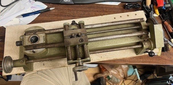
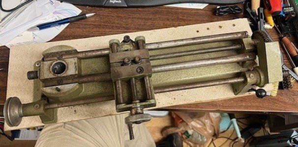
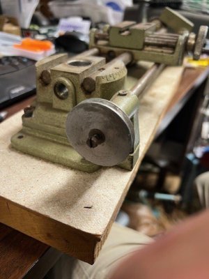
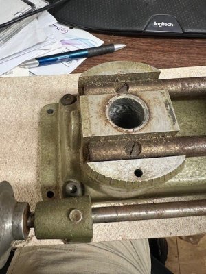
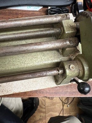
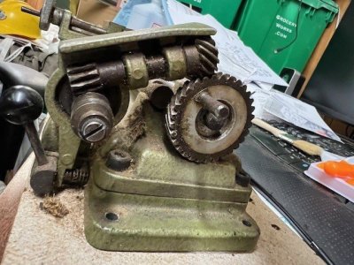
OK, now onto the mounted base and Power Feed Attachment mounted with the base. As shown in photo, the base was mounted to a nice heavy piece of wood for support, first step in disassembly is to unscrew the unit from wooded support base, just 4 wood screws, but I had to hunt more tools as they were a mix of Philips and slotted screws, and I only had imperial screw driver on hand! Sorry for the joke to my metric using friends.

With the wood base removed the power feed base was unscrewed from lathe base, two allen screws on each end.

This then gave me a separate unit to break down in another post, and a base assembly for the lathe.

SL 1000 Mounted.jpgpower feed pulley.jpgpower feed drive pulley.jpgpower feed control lever.jpgpower feed end gears.jpg
 
H

Hi Kurt,

Well done on your purchase, once cleaned up it should give you hours of good service.

I would like to suggest having a look at the brushes on the motor to check them for wear, being careful not to swap them or spin them around they need to go back in the same orientation that they were removed in, while they are out a quick clean to remove the dust inside the motor is a good thin to do. You may already be aware of all this but I thought I would mention it.

Cheers,
Stephen.
Thanks for the heads up, I have planned to give the unit a good inspection, and have pulled on brush already, a bit fiddly to get the brush and cap back in straight. These early U90 motors were a sealed unit, and had heat issues which limited the operating time for operations. Typically limited to 7-8 minutes under load and then 5 minute to cool down.
 
My, you are doing a good job of recording your progress.

All looks sound to me; as you say, a clean up and re lube and you will be turning in no time.

Unimat made their own (now exceptionally rare) left hand screwdriver.

Don't forget the machine head can be rotated to facilitate taper turning... neat!

I'm following this thread avidly.

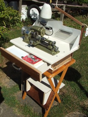
You invited contributions from others, so here's my attempt at making a useful little workstation from stuff lying around. It folds away neatly; I store the 3 lathes I have safely in a re-purposed bank tellers drawer.

I have many photo's of interesting related stuff if you are happy for me to do so?

DSCF1327.JPG
 
Last edited:
Some good information on these machines is at:
A group from the dawn of the internet but still going and a good archive. The SL is a little later than the DB, and made from Zamak instead of iron. I had a tablesaw attachment for mine but it was pretty puny. I sold it and paid for most of the original machine.
 
Last edited:
Some good information on these machines is at:
A group from the dawn of the internet but still going and a goof archive. The SL is a little later than the DB, and made from Zamak instead of iron. I had a tablesaw attachment for mine but it was pretty puny. I sold it and paid for most of the original machine.

I am a member of this group already, lots of good files to review.
 
Back
Top