• SUBSCRIBE TO SHIPS IN SCALE TODAY!

    The beloved Ships in Scale Magazine is back and charting a new course for 2026!
    Discover new skills, new techniques, and new inspirations in every issue.

    NOTE THAT OUR NEXT ISSUE WILL BE July/August 2026
  • Win a Free Custom Engraved Brass Coin!!!
    As a way to introduce our brass coins to the community, we will raffle off a free coin during the month of August. Follow link ABOVE for instructions for entering.

USCG Harriet Lane - Model Shipways 1:96 by DocTom

Chuck,
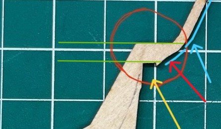
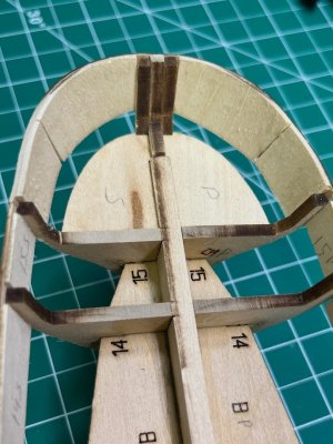
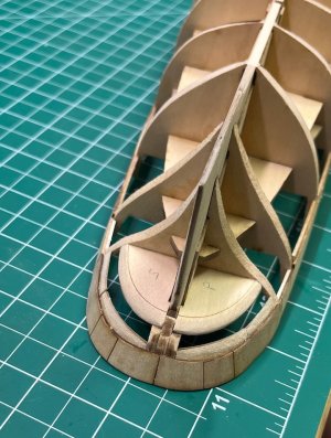
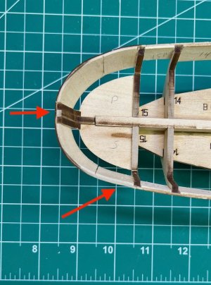
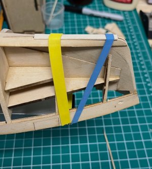
That’s right. The lower part of your blue line is where the aft end of the stern knuckles sit.
Tom! I just finished a training exercise and haven't had a chance to get to the shipyard yet. I'll try to refresh myself with the instructions I still have :cool: and get back to you in a bit. Even if I can't be helpful, I'll get back to you and let you know that I can't helpROTFROTFROTF

Blessings.
Chuck
 
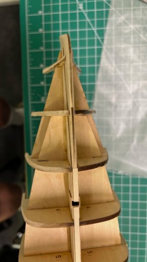
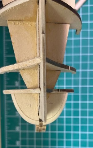
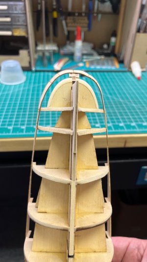
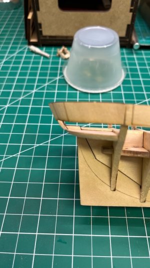
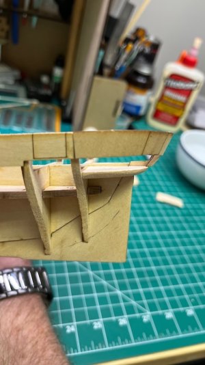
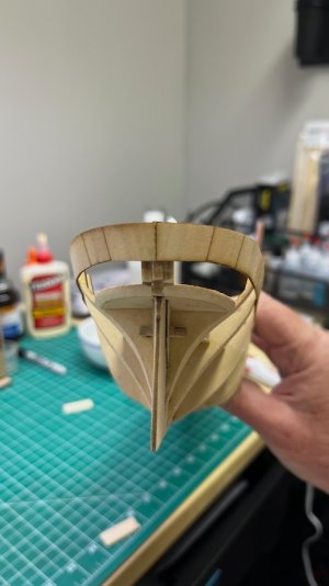
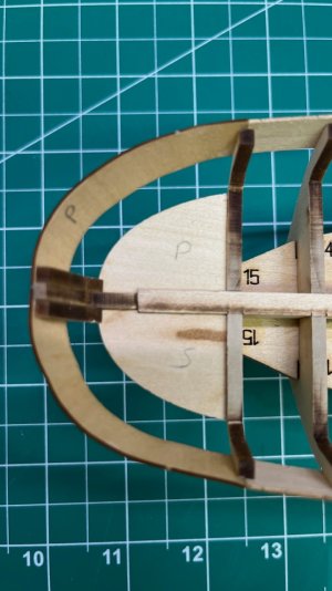
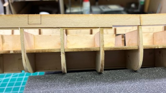
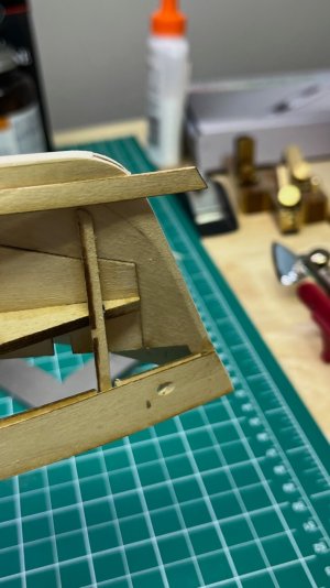
Tom! I'l looking at the instrucitons p. 5 Step 5 "Stern knuckle pieces" to p. 6-7 Step 7 "Bulwarks & upper counter."

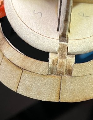
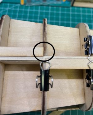
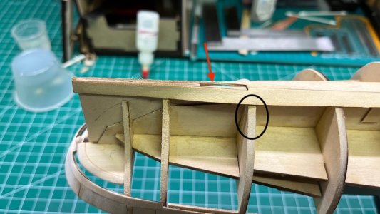
Okay - I finally see the issue. Tom, I wrote this whole long post and went back to your picture and blew it up. Once I did that I deleted tons of awesome didactic exposition:eek::eek::eek: because the blown-up ic showed my eyes, finally, what you are talking about. See giant red arrow. ROTFROTFROTF

hl stern framing 3.jpeg

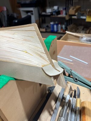
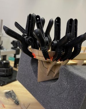
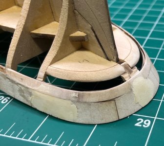
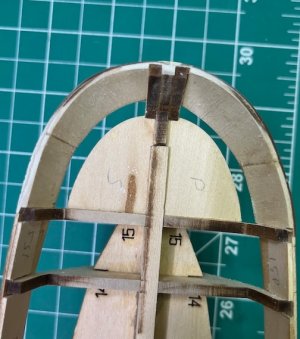
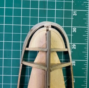
You are right! :D- the knucle doesn't follow the line established by that dent. IMHO - and I mean, truly, opinion - fit your knuckle pieces and make nice curves outboard that mirror the pics in the instructions on pp 6 & 7. Once those pieces are in and dry - fill the dent and sand to match the curves of the knuckle pieces.

I hope that helps.

Blessings.
Chuck
 
Post 8 - Fair is Bow and Bow is Fair

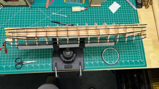
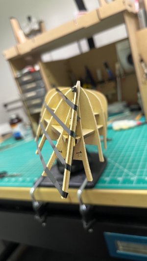
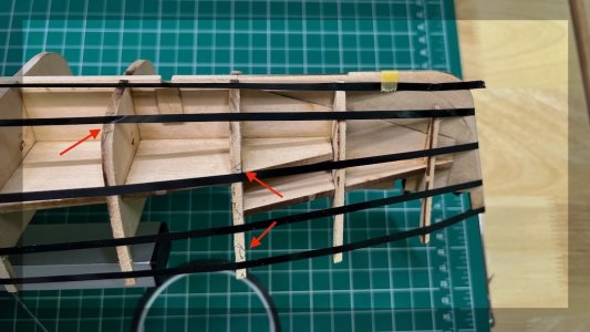
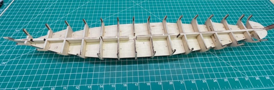
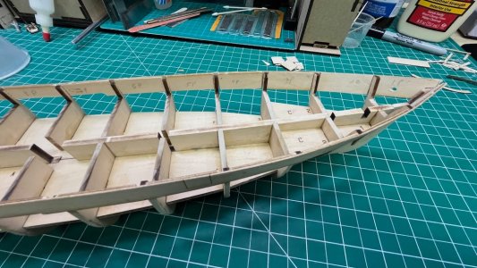
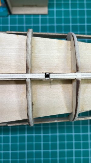
I spent time over the past 3 days fairing Harriet's hull. I first used thin black artist tape (used to make lines on white boards) to make sure the bulkheads were all aligned. It showed I needed to shim Bulkheads 5 and 7 on the port side, and 9 on the starboard side. I glued on 1/32 x 1/8 shims and let them dry overnight. The 5 and 9 shims only needed to go to the horizontal piece A, but 7 had to go to around the curve of the bilge.

IMG_5526.jpeg IMG_5527.jpeg IMG_5528.jpeg

Then I started to sand. I took the advice of the instructions and used 100g sandpaper on flexible sanding sticks. I had used 120g on my prior builds. The extra oomph made it easier. I started with the bow and worked my way back.
IMG_5534.jpeg Fairiing started.jpeg

I used the artist tape to check on my progress after I thought it looked good. I find the tape makes it easier to detect areas that need more refinement, compared to sliding a planking strip along the bulkheads.
testing starboard side.jpeg
Testing Starboard bow fairing.jpeg

I mark areas that needed more work with a pencil:
marked for more.jpeg

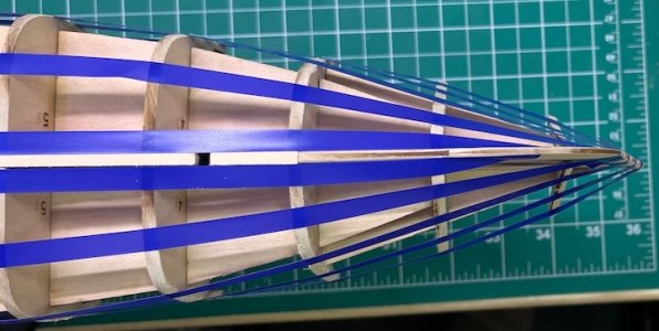
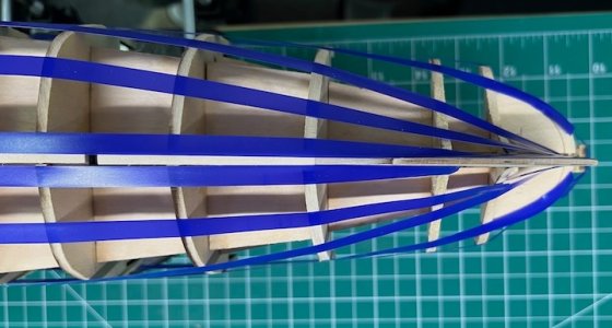
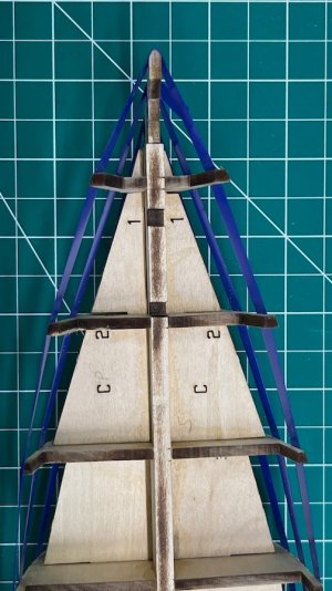
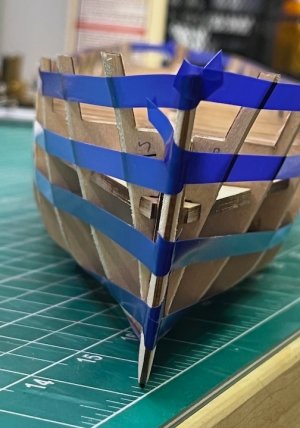
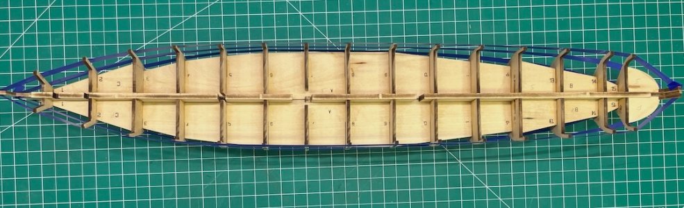
The only issue with the artist tape is that it isn't very sticky. But you can reuse it to recheck your progress by just holding it against the bulkheads. When I thought I had a fair hull I used 3M masking tape for a final check. Of course you can't assess the very stern because the stern counter isn't installed.
bow (2).jpeg
stern (4).jpegbow from above.jpeg bow from front.jpegfinished?.jpeg

It looks good to me. I will let it marinate overnight and re-assess it in the morning to see if I still am still happy with it, but I think I will be. Overall, I found it easier to fair this hull compared to my last build, the Model Shipways Lobster Smack. The larger size and shape of the hull meant less and more gradual curves.

My plan is to fair the top of the bulkheads to the central spine tomorrow, and then try to wrap my head around the bulkheads. They are the major problem with this kit (in addition to which guns to use and where to place them - plus where the wheel goes).

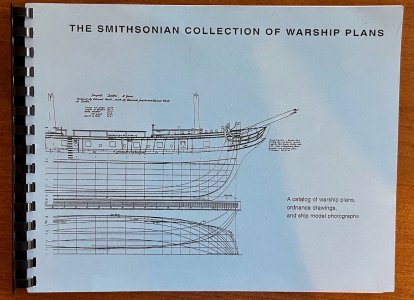
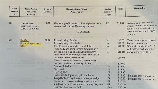
On that note, I have figured out how to obtain the plans for the Harriet Lane from the Smithsonian Institution. They were created in the 1960s, and are supposedly the basis for this kit. For $15 I'll see if they shed any light on the issues of gun placement and the location of the auxiliary wheel.

Now, to complete my initial quote, it's into "the smog and filthy air" of the Canadian wildfire smoke.
 
Post 9 - The Bulwark Problem Solved?

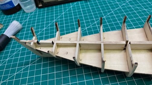
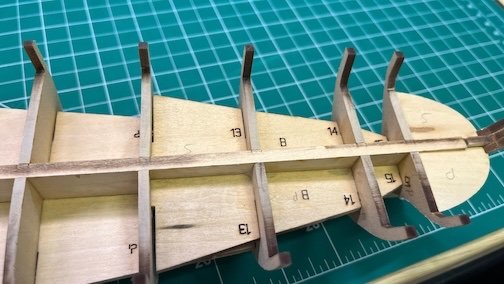
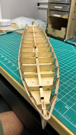
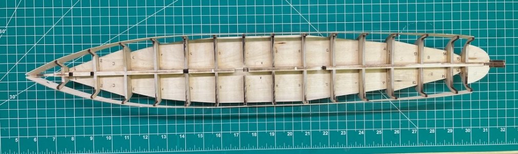
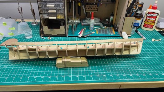
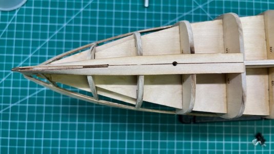
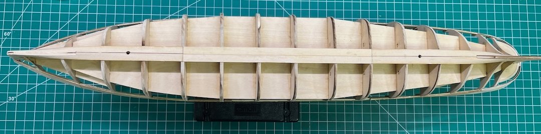
When I looked at the hull again yesterday, I saw a few spots that needed a little more fairing, mainly on bulkhead 3. I then faired the tops of the bulkhead to the central spine.
Faired top of bulkheads fore.jpeg And aft.jpeg

Done fairing.jpeg

With that the fairing is complete (at least until I start planking)!

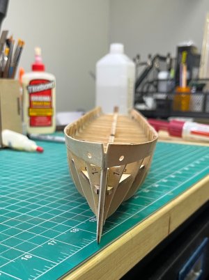
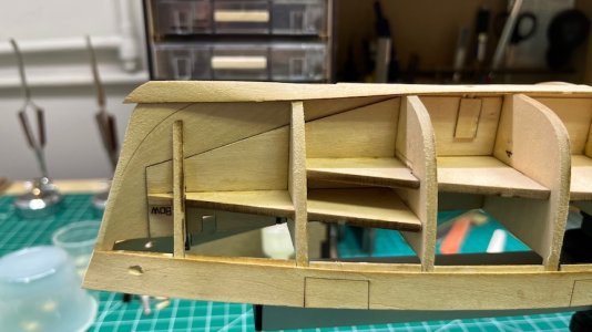
I've been mulling over the bulwark issue for the past several days, aided by @The Gavel . One of the major complaints in build logs of this kit is that the bulwarks are too low for the guns to fit properly, and most peope don't realize that until it's too late. The instructions tell you to glue the outer bulwarks at the level of the deck, but of course the deck isn't installed yet! The plans show the height of the inner bulwark to be 18/32" above the deck midships. The inner bulwark pieces measure 17/32", and the outer bulwark pieces 16/32". If you glue the outer bulwarks at the level of the deck they will obviously be too short.

The top of the bulwarks midship need to be 19/32" above the top of the bulkheads (18/32 for the bulwark height + 1/32 for the deck). The inner bulwark would therefore sit 1/32" above the deck, but that would be covered by the 1/8" spirketting.

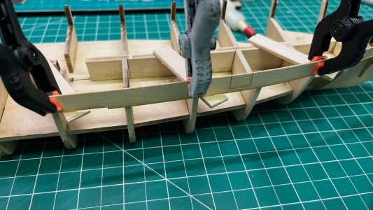
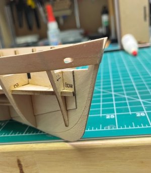
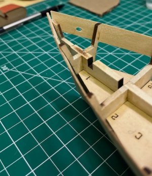
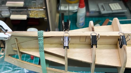
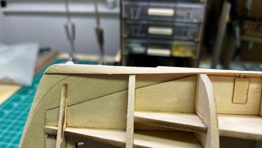
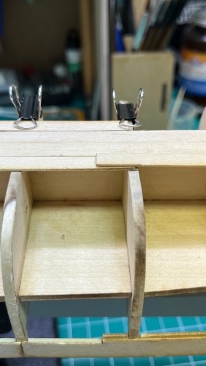
That also means the outer bulwark pieces need to sit 3/32" (3/32 + 16/32 = 19/32) above the bulkheads to match the plans. Today I made 3/32" spacers from wood strips, rubber cemented them to the bulkheads, and clamped the outer bulkhead in place.
Setting height of bulwark.jpeg

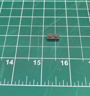
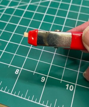
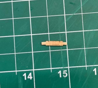
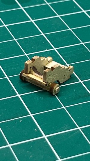
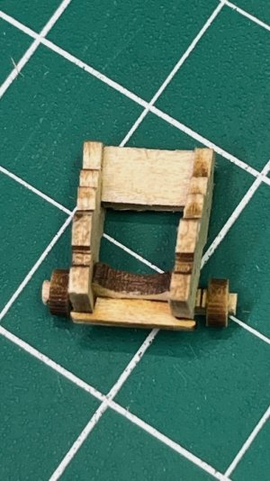
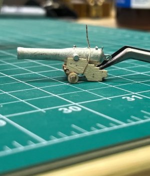
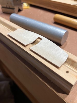
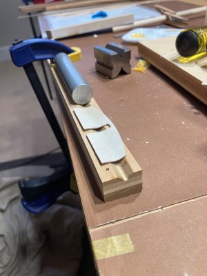
I then made up one of the cannons to test the height. My first ever gun carriage! I used a mini building block to square up the bed with the cheeks, and a small clamp to mark where the axle needed to be sanded to fit the wheels.

mini block for carriages.jpeg Jig for sanding axles.jpeg Axle finished.jpeg

Baby carriage.jpeg Top view.jpeg

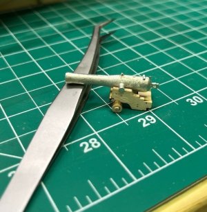
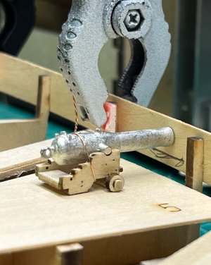
I didn't want to glue the gun yet, so I got it level, and wired it in place.
Cannon level.jpeg Cannon jigged up.jpeg

I then laid a piece of 1/32" wood on the bulkheads to simulate the deck, and placed the cannon against the bulwark:

Proof of concept2.jpeg

The line represents the bottom edge of the gun port. The gun barrel looks pretty centered to me. :) As long as I don't plank the deck, this should work out. My initial plan was to simulate planking anyway. I also hope to use @JerryTodd 's 3D printed 24 pounder Dahlgren Howitzers and 32 pounder gun (her 1858 armament), and as long as they are about the same height as the kit-supplied guns I should be OK. It looks like I will have to put spacers atop the bulkhead extensions. I also don't think this will mess up the placement of the sponsons.I guess the lesson here is don't always follow the instructions!

Next up is to bend and start installing the outer bulwarks.
 
Last edited:
Post 9 - The Bulwark Problem Solved?

When I looked at the hull again yesterday, I saw a few spots that needed a little more fairing, mainly on bulkhead 3. I then faired the tops of the bulkhead to the central spine.
View attachment 620001 View attachment 620003

View attachment 620002

With that the fairing is complete (at least until I start planking)!

I've been mulling over the bulwark issue for the past several days, aided by @The Gavel . One of the major complaints in build logs of this kit is that the bulwarks are too low for the guns to fit properly, and most peope don't realize that until it's too late. The instructions tell you to glue the outer bulwarks at the level of the deck, but of course the deck isn't installed yet! The plans show the height of the inner bulwark to be 18/32" above the deck midships. The inner bulwark pieces measure 17/32", and the outer bulwark pieces 16/32". If you glue the outer bulwarks at the level of the deck they will obviously be too short.

The top of the bulwarks midship need to be 19/32" above the top of the bulkheads (18/32 for the bulwark height + 1/32 for the deck). The inner bulwark would sit 1/32" above the deck, but that would be covered by the 1/8" spirketting.

That also means the outer bulwark pieces need to sit 3/32" (3/32 + 16/32 = 19?32) above the bulkheads to match the plans. TodayI made 3/32" spacers from wood strips, rubber cemented to the bulkheads, and clamped the outer bulkhead in place.
View attachment 620004

I then made up one of the cannons to test the height. My first ever gun carriage! I used a mini building block to square up the bed with the cheeks, and a small clamp to mark where the axle needed to be sanded to fit the wheels.

View attachment 620005 View attachment 620006 View attachment 620007

View attachment 620008 View attachment 620009

I didn't want to glue the gun yet, so I got it level, and wired it in place.
View attachment 620010 View attachment 620011

I then laid a piece of 1/32" wood on the bulkheads to simulate the deck, and placed the cannon against the bulwark:

View attachment 620012

The line represents the bottom edge of the gun port. The gun barrel looks pretty centered to me. :) As long as I don't plank the deck, this should work out. My initial plan was to simulate planking anyway. I also hope to use @JerryTodd 's 3D printed 24 pounder Dahlgren Howitzers and 32 pounder gun (her 1858 armament), and as long as they are about the same height as the kit-supplied guns I should be OK. It looks like I will have to put spacers atop the bulkhead extensions. I also don't think this will mess up the placement of the sponsons.I guess the lesson here is don't always follow the instructions!

Next up is to bend and start installing the outer bulwarks.

Looks like great planning!

Rob
 
Back
Top