• Ships of Scale has incorportated an extra level of security when you log In. Please follow on-screen prompts to acknowledge that you are not a robot via a "Check Box" or a "Pictorial Check Box Puzzle". This is needed due to higher level of AI Activity Security.
  • SUBSCRIBE TO SHIPS IN SCALE TODAY!

    The beloved Ships in Scale Magazine is back and charting a new course for 2026!
    Discover new skills, new techniques, and new inspirations in every issue.

    NOTE THAT OUR NEXT ISSUE WILL BE July/August 2026
  • Win a Free Custom Engraved Brass Coin!!!
    As a way to introduce our brass coins to the community, we will raffle off a free coin during the month of August. Follow link ABOVE for instructions for entering.

USCG Harriet Lane - Model Shipways 1:96 by DocTom

Post 35 - The Rudder

I touched up the damaged paint on the keel using a brush, then test fit and corrected the waterline on the rudder.

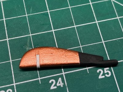
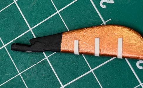
The instruction manual has you glue paper or card strips to represent the straps of the rudder pintles and gudgeons, but gives no guidance on size, placement, etc, other than that they are 1/32" wide. The Harriet Lane plans I purchased from the Smithsonian luckily show the top pintle strap, which measures 4.5mm at scale. I used the manual's picture of the rudder with the straps in place to figure out the rest. I measured the diagonal length of the rudder in the picture (68mm) and of the real rudder (44mm), and used that fraction 44/68 = 0.647 to calculate the lengths of the straps and their distance from the bottom of the rudder, based on the measurements in the picture. The bottom strap is 6.5 mm on one side, and the lower edge is 9mm from the bottom of the rudder. The middle is 6mm long and 17mm from the bottom of the rudder. The top is 4.5 mm (happily matching the plans!) and 24.5 mm from the bottom. The straps on the hull are all 11mm long.

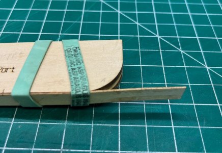
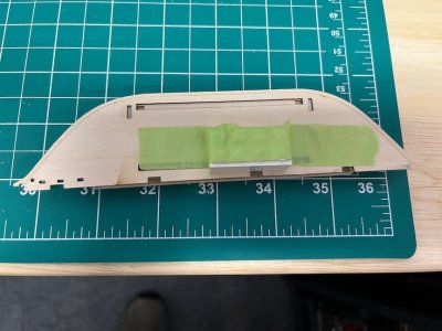
I cut strips from card stock. I made tick marks on the rudder at the appropriate places. I glueed a strip to the rudder lined up with the tick marks (added some tape to keep it from moving), wrapped it around to the other side, marked it at the tick mark there, cut it and glued it.
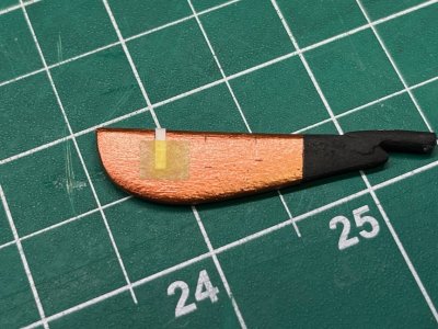
Pintle taped in place.jpeg
The other side cut and glued.jpeg

Repeat as necessary:
Three pintles.jpeg

After painting them, I attached the rudder and then the gudgeon straps
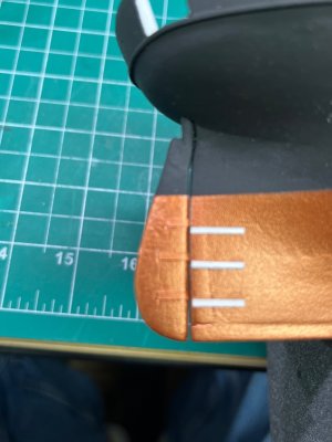
Gudgeon straps.jpeg

Sorry for the out of focus picture :oops: After some more copper paint, the rudder is complete.
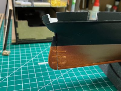
rudder finished.jpeg

Now I can finally tackle the paddle wheel/water closet assemblies.

One question I have for the more experienced modelers. Should I put a matte clear coat on the hull? I didn't do that with my prior models, but something tells me I should with the matte black paint. Any advice would be greatly appreciated.

 
I would spray the copper paint with a clear matte lacquer. Try on scrap first! Topsides look fine although like chicken soup, a coat there to can’t hurt.

Roger
 
Post 36 - The Paddlewheel Assemblies, Part 1.

This is going to take a while. I've ordered some Testors Dullcote from Mr. Amazon, but haven't decided if I will use on the hull (I probably will), but in the meanwhile I started to make the paddlewheels with bonus sea-going outhouses. First up was gluing the two sponson pieces. Easy enough!
Sponsons glued.jpeg

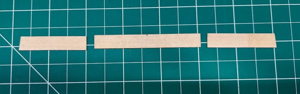
As was gluing the lower paddle box forming pieces with spacer. Then came the first Model Shipways moment. The instruction manual clearly shows that the framing piece is meant to be a continuous piece of bass wood, but mine both came in three pieces:
Separate pieces.jpeg

They got a little heavy handed when laser marking where the ends of PE grill that is eventually glued to this fits. BTW, I have the end pieces upside down in this picture - but that's another story.

I glued the center section to the forms, and then glued the two end pieces
Gluing the bits.jpeg
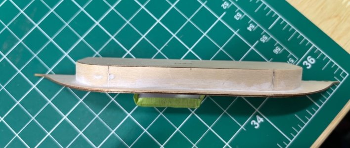
after letting them dry overnight, I used a little water and my electric plank bender to curve them to the forms. Before I glued them to the sponsons, I checked their fit against the hull. I used a Lego brick to keep the sponson perpendicular to the hull
Lego brace.jpeg

And trimmed the ends of the framing pieces so the top of the lower paddle box was flush with the hull.
Trial run.jpeg

Once I was satisfied with this I marked their location and glued the lower paddle boxes to the sponsons.

Complete.jpeg

They looked fairly perpendicular, and were flat across the top:
Looking perpendicular.jpeg

The test fitting made me realize I had cut the rub rails too short where they meet the paddle boxes. I therefore extended them to fill the gaps
Extended rub rail.jpeg
Filled gap.jpeg

I will prime and paint them before I apply the clear coat to the hull. I'll also get all the dust off the hull as well!
 
Last edited:
Post 37 - The Paddlewheel Assemblies, Part II

Before starting on the upper paddle wheel boxes I filled and sanded the gaps on the lower boxes

Cleaned up lower paddlebox.jpeg

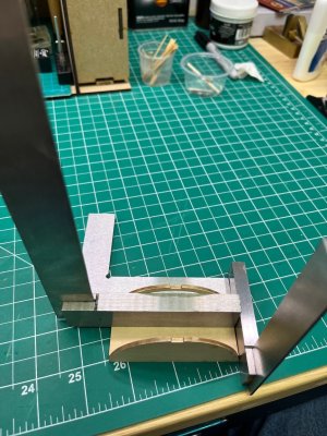
The semicircular paddle wheel frames went together fairly easily. I loaded up on the set squares to keep everything, well, square.
Gluing frame.jpeg

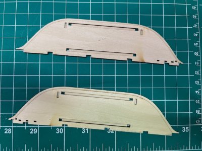
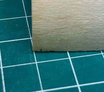
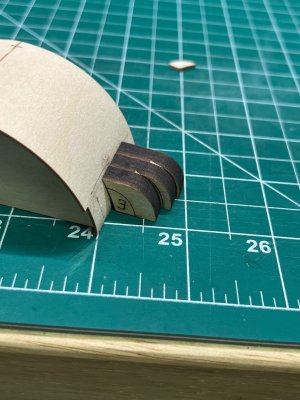
The cross braces extend beyond the frames (and are also too wide. I tried to trim each side equally, but the center mark ended up being cockeyed). I trimmed them flush, based on pictures in the instruction manual, although it doesn't mention this. I assigned one frame port and one starboard. I set the tick mark on the first half-cover on the edge of the port frame and eyeballed keeping the overhang equal. After I glued the second half, I realized they weren't square to the frames. While I unglued them, I realized the simplest way to make sure that they would sit true on the frame was to replicate the tick marks on the top ends of the pieces at the bottom:
Tick mark on lower edge too.jpeg
This guaranteed that the outside overhang was an even 4/32" all the way around.

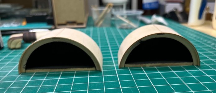
I painted the insides black,
Upper paddle boxs done..jpeg
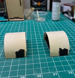
and thanks to @The Gavel I knew to paint a black patch on the outside, opposite of where the portholes of the water closets will be!

Painted on the outside.jpeg

The framed and bent covers of the water closets went together the same way. I used the paddle box to lineup the corner pieces.
Aligning end pieces.jpeg

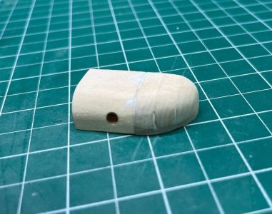
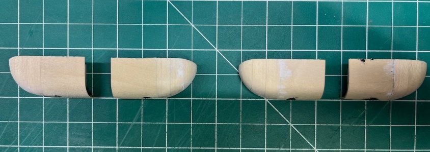
After gluing them to the frames I used my Dremel tool to remove most of the wood for the sanding steps, followed by 100-grit and 120-grit sanding blocks. The first two steps were obvious, as there are pre-existing curves to follow. I used a compass to scribe a quarter circle on the back of the piece to make a guideline for the third sanding step. I did the fourth step freehand. Finished it off with 120-grit and 240-grit flexible sanding pads. It needed a little filler, but I think it came out well:
Before and after.jpeg
Aft watercloset, port side.jpeg
I'm not sure why you glue the 4th shaping block to the corner piece, as you completely remove it while sanding.
I painted the insides black, although the instructions don't mention this, based on @The Gavel's build log.

One down, three more to go! The hardest part will be trying to make them all look exactly the same :)

When I first read through the instruction manual, this step seemed impossible - I couldn't imagine how I would do it. But, as I have discovered over and over in my short modeling career, what seems intimidating on paper becomes obvious when you have the wood in your hands.
 
Last edited:
Post 37 - The Paddlewheel Assemblies, Part II

Before starting on the upper paddle wheel boxes I filled and sanded the gaps on the lower boxes

View attachment 641831

The semicircular paddle wheel frames went together fairly easily. I loaded up on the set squares to keep everything, well, square.
View attachment 641830

The cross braces extend beyond the frames (and are also too wide. I tried to trim each side equally, but the center mark ended up being cockeyed). I trimmed them flush, based on pictures in the instruction manual, although it doesn't mention this. I assigned one frame port and one starboard. I set the tick mark on the first half-cover on the edge of the port frame and eyeballed keeping the overhang equal. After I glued the second half, I realized they weren't square to the frames. While I unglued them, I realized the simplest way to make sure that they would sit true on the frame was to replicate the tick marks on the top ends of the pieces at the bottom:
View attachment 641832
This guaranteed that the outside overhang was an even 4/32" all the way around.

I painted the insides black,
View attachment 641834
and thanks to @The Gavel I knew to paint a black patch on the outside, opposite of where the portholes of the water closets will be!

View attachment 641837

The framed and bent covers of the water closets went together the same way. I used the paddle box to lineup the corner pieces.
View attachment 641833

After gluing them to the frames I used my Dremel tool to remove most of the wood for the sanding steps, followed by 100-grit and 120-grit sanding blocks. The first two steps were obvious, as there are pre-existing curves to follow. I used a compass to scribe a quarter circle on the back of the piece to make a guideline for the third sanding step. I did the fourth step freehand. Finished it off with 120-grit and 240-grit flexible sanding pads. It needed a little filler, but I think it came out well:
View attachment 641835
View attachment 641836
I'm not sure why you glue the 4th shaping block to the corner piece, as you completely remove it while sanding.
I painted the insides black, although the instructions don't mention this, based on @The Gavel's build log.

One down, three more to go! The hardest part will be trying to make them all look exactly the same :)

When I first read through the instruction manual, this step seemed impossible - I couldn't imagine how I would do it. But, as I have discovered over and over in my short modeling career, what seems intimidating on paper becomes obvious when you have the wood in your hands.
Nice Job! Really looks good!
 
Post 38 - The Paddlewheel Assemblies, Part III

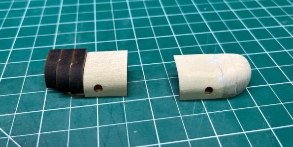
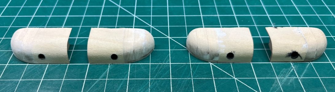
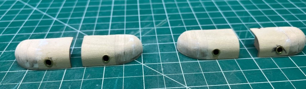
I finished up the other 3 water closets today. I refined my method a little, using a Japanese pull saw to trim most of the wood off the first sanding step, and using my Dremel tool to remove some of the wood for the second step. It saved some sanding. I tried to match the contours of the first one I made. I'm pleased with the results, although I am not sure how closely they resemble the real things.
4 WCs in  arow.jpeg
From the top.jpeg

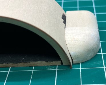
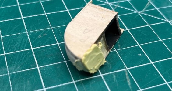
After filling and painting the insides black I tried to sand them to get a close fit to the paddle wheel boxes. I used 100g sandpaper rubber cemented to the boxes as a guide. It kind-of worked.
Will need some filler.jpeg

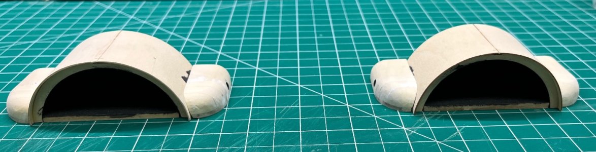
I don't think I want to be more aggressive with the sanding, so I will use filler for the cracks. They look better from a distance:
Preview of paddleboxes.jpeg

That's it for now!
 
Last edited:
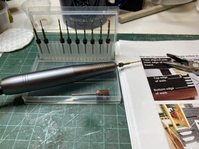
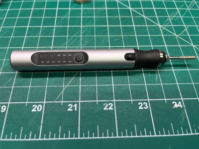
Tom, your work looks great. While I have a Dremel, my go to tool, especially for light sanding and drilling is a nail drill. They are very inexpensive (I bought mine for $12) come with a sanding drum, you can get replacement drums of different grits very cheaply. They will also accept arrowmax drills which work nicely. They take a 3/32" shank so Dremel bit will NOT work. You can also get carving bits for them. You can get them corded (work off a phone charger brick) or cordless.

The advantage is they are so small and fit well in your hands. They do not have the torque of a Dremel but for the soft woods we use, it works just fine.

Rob

IMG_0275.jpeg
 
Tom, your work looks great. While I have a Dremel, my go to tool, especially for light sanding and drilling is a nail drill. They are very inexpensive (I bought mine for $12) come with a sanding drum, you can get replacement drums of different grits very cheaply. They will also accept arrowmax drills which work nicely. They take a 3/32" shank so Dremel bit will NOT work. You can also get carving bits for them. You can get them corded (work off a phone charger brick) or cordless.

The advantage is they are so small and fit well in your hands. They do not have the torque of a Dremel but for the soft woods we use, it works just fine.

Rob
I have something similar that I bought from Mr. Amazon. I tend to use my Proxxon dremel-like tool for wood rough work, and the mini drill for finer stuff and cleaning up Britannia.
 
Post 39 - The Paddlewheel Assemblies, Part IV

Lots of visible progress over the past two days, all of which went very easily and according to the instruction manual for the most part. I had an idea for filling the gaps when I saw my pictures of the WCs against the paddle wheel boxes - smushing putty against the WCs and sanding it by hand - that didn't work.
Fixxing the gaps.jpeg

It fixed the gaps, but left the WCs at an angle to the paddles boxes, which would throw off the bulkhead that sits behind all this stuff (more on that later!). So I removed it all.

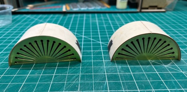
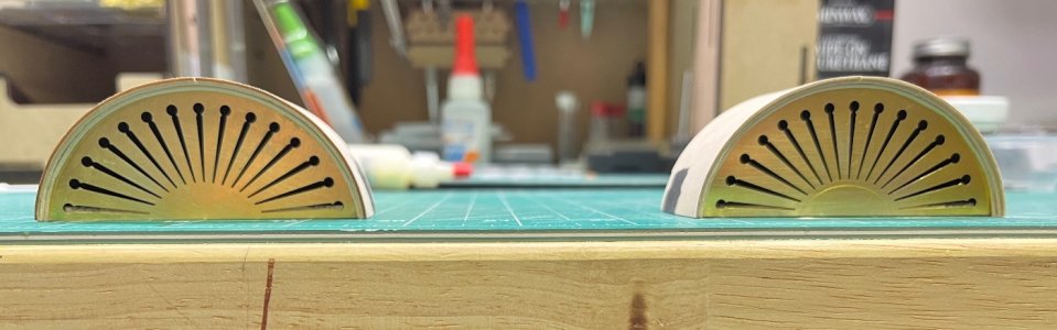
I then started on the PE brass. The screens in the front of the paddle boxes needed some trimming at the bottom edges to fit properly. My mini etching pen from Amazon did the trick. I used 5-minute epoxy to attach the brass.
Mini rotary tool.jpeg
Brass screens.jpeg

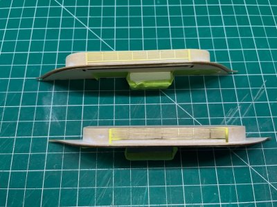
The grills on the lower paddle boxes went on easily with very small dabs of epoxy:
Brass vents.jpeg

The WC port hole trim required very, very small dabs of epoxy. I just bent them against the WCs using the flat end of a tweezer handle while gluing them, instead of following the instructions and bending them around a 1/2"dowel.
Port hole trim in place.jpeg

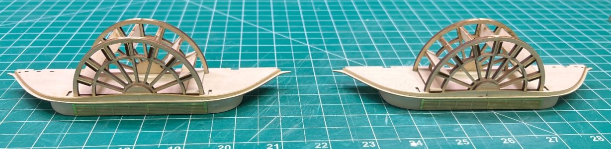
The paddle wheels went together seamlessly, as did the skirting
Paddle wheels done.jpeg

While the glue dried on the wheels I adde the optional trim to the paddle boxes
Molding detail.jpeg

Next up is gluing the upper assemlies together. Looking forward, I am trying to wrap my head around how the bulkheads on the inner aspect of all this fits. I don't want to glue anything until I figure this out.

A question to any reader who has built this kit: Do the bulkheads sit flush against the inner edge of the paddle box/WC assembly, or do they fit inside them?
 
I would say mine are flush with the edge of the assembly as my assembly slightly overhanging the bulwarks and then the bulkheads were glued against the bulwarks that then caused them to be flush with the edge of the assembly. Hope that makes sense. Please look at my June 11, 2026 posting of my build of the Harriet Lane for photos, showing what I mean.
 
Back
Top