-

Win a Free Custom Engraved Brass Coin!!!
As a way to introduce our brass coins to the community, we will raffle off a free coin during the month of August. Follow link ABOVE for instructions for entering.
-

PRE-ORDER SHIPS IN SCALE TODAY!
The beloved Ships in Scale Magazine is back and charting a new course for 2026!
Discover new skills, new techniques, and new inspirations in every issue.
NOTE THAT OUR FIRST ISSUE WILL BE JAN/FEB 2026
You are using an out of date browser. It may not display this or other websites correctly.
You should upgrade or use an alternative browser.
You should upgrade or use an alternative browser.
You can choose the Thumbnail option
most of the members like the full size photos (me included)I thought it's easier to navigate the page with small pictures...
The thumbnails are clickable and opens up to full sizemost of the members like the full size photos (me included)
Click on a thumbnail image with the cursorDo you explain it to me?
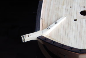
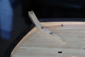
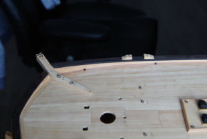
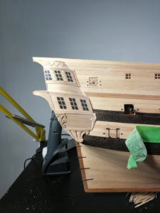
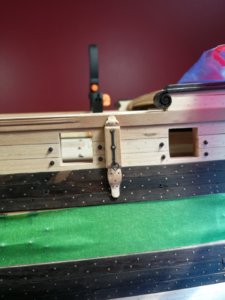
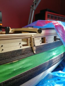
Your cathead is looking very good - very well done
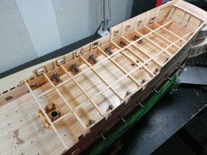
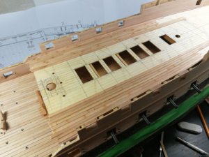
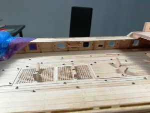
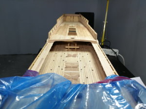
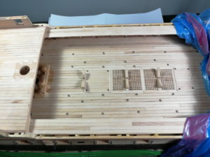
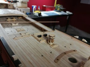
There is a big mistake in the kit in mast locations and edges of the forecastle and quarterdeck. For example, the distance between main mast and quarterdeck edge should be almost 10 mm bigger. I didn't correct anything, just adapted my building. And it's not a scale difference, I checked and rechecked and rechecked again. The prints of my drawings are 0.5% accurate. The keel length on computer is 860.4, on prints - 856, and on the ship - 858.
In any case during this rechecking I was surprised to find out that my prints are different from computer files (as I mentioned for example keel length 856 vs. 860.4). Also, different prints were in slightly different scale, but no more than 0.5%. I printed them on big plotter and didn't bother checking. Lesson learnt - in future I will always check some big dimensions on everything I print.
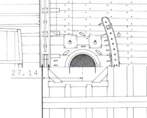
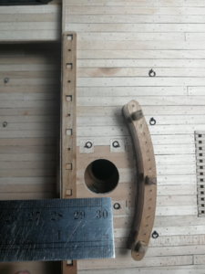
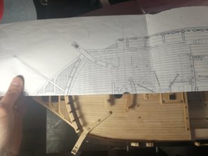
In any case during this rechecking I was surprised to find out that my prints are different from computer files (as I mentioned for example keel length 856 vs. 860.4). Also, different prints were in slightly different scale, but no more than 0.5%. I printed them on big plotter and didn't bother checking. Lesson learnt - in future I will always check some big dimensions on everything I print.


Last edited:
Very interesting photos and explanations -Your problem with the mast location is showing once more the necessity to check everything twice or even more.
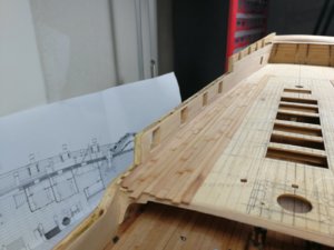
Very interesting is your photo showing half deck on the plan and your model - great idea to show the problem
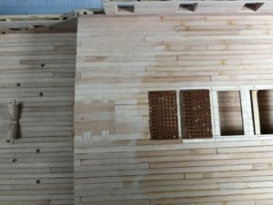
I realized on your photos some small pencil circles on each plank. It can not be the location of treenails, due to the fact that the circles are forming a small bow and are not rectangle to the keel......what was the reason of these markings (red arrows)?
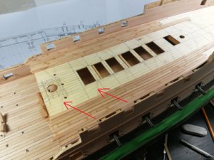
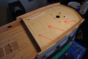


For the circles:
This is how I do the markup for deck or hull planking. I print piece of paper that is divided to equal segments. The quantity of the segments is equal to the quantity of the planks on the deck per side. Using this piece of paper I am able to divide the deck width (from centerline to waterway piece) at any place by the same number of planks, and they all will have equal width regardless of the local deck width. Like this:

When the deck width becomes smaller you just tilt more the piece of paper, it still gives you equal division.
Now, I put the marks not with a pencil, but with a knife. It's much more precise. And finally, to highlite the knife marks I just circle them with pencil - to be able to quickly find them and not loose
This is how I do the markup for deck or hull planking. I print piece of paper that is divided to equal segments. The quantity of the segments is equal to the quantity of the planks on the deck per side. Using this piece of paper I am able to divide the deck width (from centerline to waterway piece) at any place by the same number of planks, and they all will have equal width regardless of the local deck width. Like this:

When the deck width becomes smaller you just tilt more the piece of paper, it still gives you equal division.
Now, I put the marks not with a pencil, but with a knife. It's much more precise. And finally, to highlite the knife marks I just circle them with pencil - to be able to quickly find them and not loose
Very good way for marking the width of planks - many thanks for the explanationFor the circles:
This is how I do the markup for deck or hull planking. I print piece of paper that is divided to equal segments. The quantity of the segments is equal to the quantity of the planks on the deck per side. Using this piece of paper I am able to divide the deck width (from centerline to waterway piece) at any place by the same number of planks, and they all will have equal width regardless of the local deck width. Like this:
View attachment 106296
When the deck width becomes smaller you just tilt more the piece of paper, it still gives you equal division.
Now, I put the marks not with a pencil, but with a knife. It's much more precise. And finally, to highlite the knife marks I just circle them with pencil - to be able to quickly find them and not loose

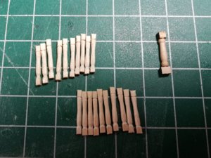
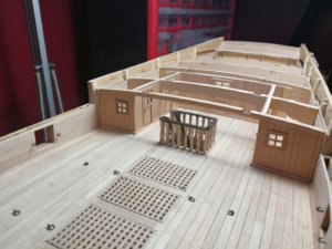
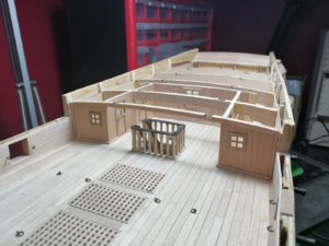
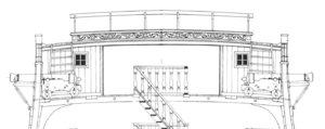
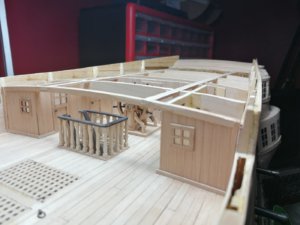
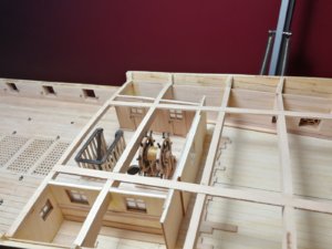
Your work is looking very good my friend -For the officers ladder I did completely all new parts
View attachment 107047View attachment 107048View attachment 107049
the balustrade is looking relatively high in comparison to the free height from deck to the beam


