
-

SUBSCRIBE TO SHIPS IN SCALE TODAY!
The beloved Ships in Scale Magazine is back and charting a new course for 2026!
Discover new skills, new techniques, and new inspirations in every issue.
NOTE THAT OUR NEXT ISSUE WILL BE July/August 2026 -

Win a Free Custom Engraved Brass Coin!!!
As a way to introduce our brass coins to the community, we will raffle off a free coin during the month of August. Follow link ABOVE for instructions for entering.


You are using an out of date browser. It may not display this or other websites correctly.
You should upgrade or use an alternative browser.
You should upgrade or use an alternative browser.
USS Constitution - Model Shipways MS2040 - 1:76 - by Jeff T

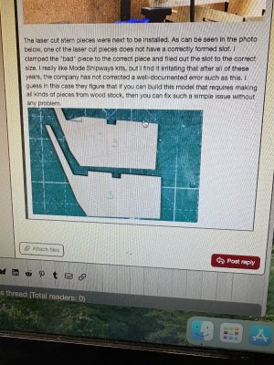


If you check this post (#22) you can see where they fit at the stern. https://shipsofscale.com/sosforums/...pways-ms2040-1-76-by-jeff-t.14159/post-435349
Picking up what I have been doing for the last number of months. I am going to primarily post pictures without much explanation. I will try to add text where I did something other than following the plans.
This post focuses on installing gratings. There are a couple of things specific here to look at. I added planking under some of the gratings to represent the planks on the gun deck.
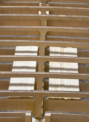
I built out areas for deck planks to be attached.

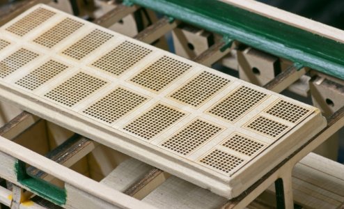
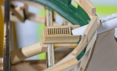
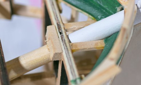
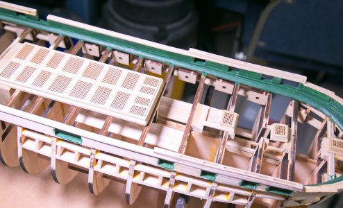
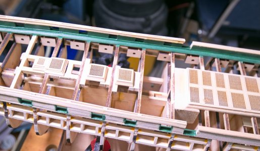
This post focuses on installing gratings. There are a couple of things specific here to look at. I added planking under some of the gratings to represent the planks on the gun deck.
I built out areas for deck planks to be attached.
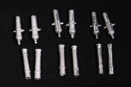
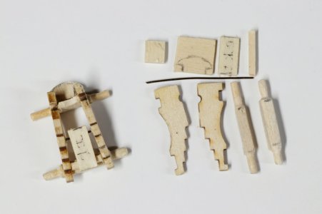
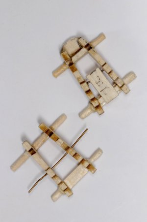
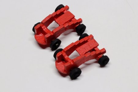
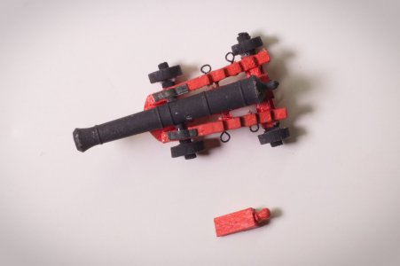
While I was working on the hull, I built and painted gun carriages (both long guns and carronades). I use a wire brush on a Dremel to remove the molding residue from the barrels and painted them black.
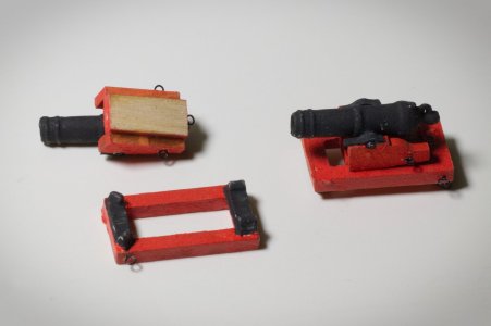
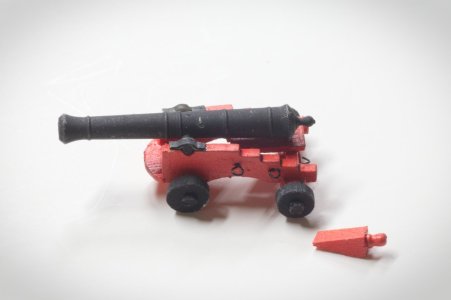
 s
s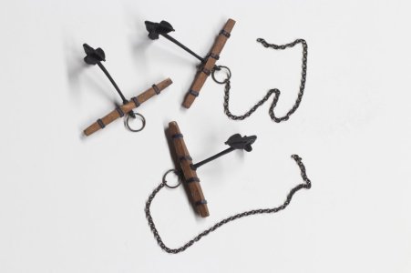
Planking the spar deck.
I don't have many pictures of planking. I found it to be more difficult than I expected. I realized after the fact that I should have put more extentions under the gratings, especially along the sides (I didn't put any there).
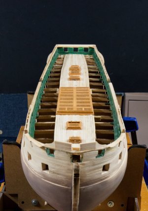
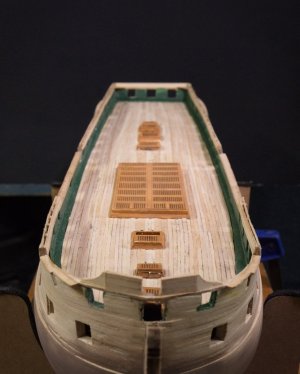
I don't have many pictures of planking. I found it to be more difficult than I expected. I realized after the fact that I should have put more extentions under the gratings, especially along the sides (I didn't put any there).


Congrats, the deck is installed. Now the challenge is leveling the deck. Found a doveltail chisel and a mini bull nose plane helps. Google search will yield vendors.
Good luck,
-Rich
Good luck,
-Rich
Painting and Coppering the Hull
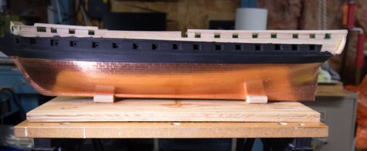
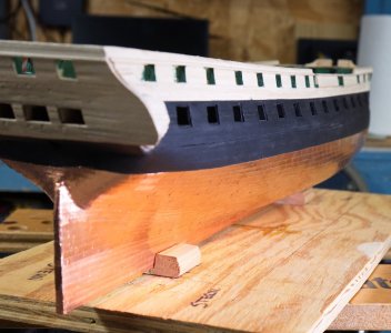
I started by masking off the bulwarks and priming the part of the hull where the copper tape would attach. I spent a lot of time fixing irregularities in the planking that showed up after priming. I then painted most of the hull black. I marked vertically where the bulkheads were located in order to use them as references for drawing the horizontal lines for each of the hull sections to be coppered. I used the copper tape supplied with the kit (as well as the remaining tape I had from my Conny cross section) to do the coppering. I set up a jig to cut the tape into the proper length. I cut about 1/32" off of the width of the 1/4" tape top get the correct width for each plate. Somewhere over 1300 individual plates were attached (I should have written that number down, but maybe it was too depressing). I thought the coppering was a success and am pleased with it.
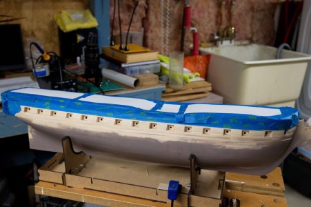
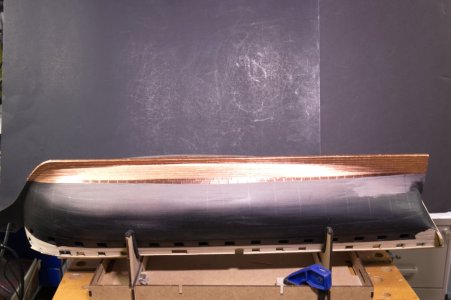
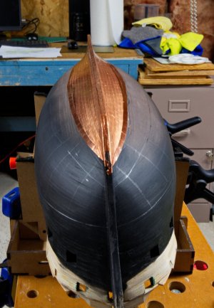
I also plated the rudder.
I started by masking off the bulwarks and priming the part of the hull where the copper tape would attach. I spent a lot of time fixing irregularities in the planking that showed up after priming. I then painted most of the hull black. I marked vertically where the bulkheads were located in order to use them as references for drawing the horizontal lines for each of the hull sections to be coppered. I used the copper tape supplied with the kit (as well as the remaining tape I had from my Conny cross section) to do the coppering. I set up a jig to cut the tape into the proper length. I cut about 1/32" off of the width of the 1/4" tape top get the correct width for each plate. Somewhere over 1300 individual plates were attached (I should have written that number down, but maybe it was too depressing). I thought the coppering was a success and am pleased with it.
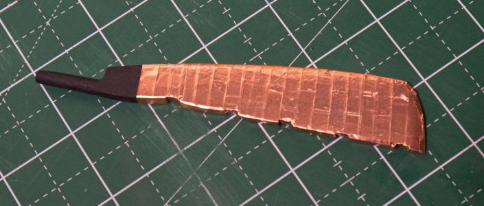
I also plated the rudder.
Primo!


Great job! There is a massive amount of work in what you just completed. As they always say a picture is worth a thousand words.
Yards, spanker boom, and gaff
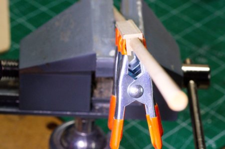
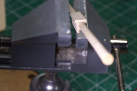
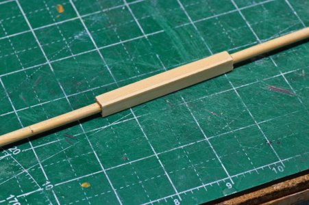
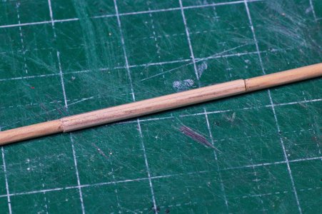
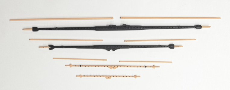
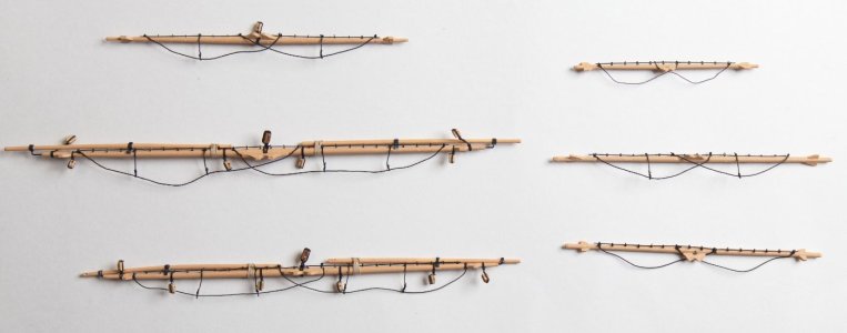
In order to break up the tedium of cutting and placing copper onto the hull, I worked on constructing the yards, boom and gaff. The octagonal parts of the bigger yards were made by gluing squares of strips around the yard and trimming and sanding down to the octagonal shape.
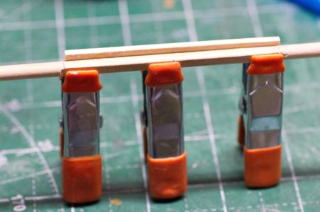
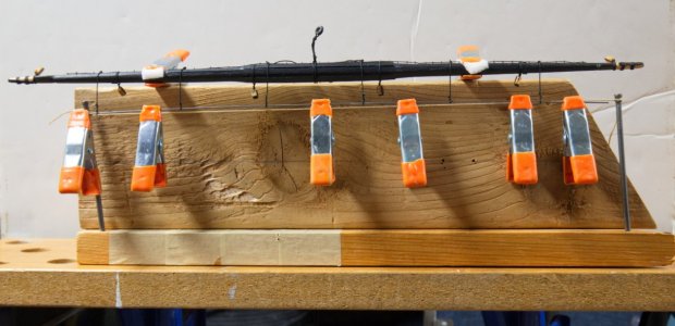
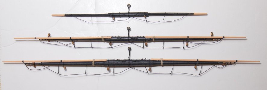
I made a simple jig to do the footropes, trying to get them even. The tan line was my target length. After I had the 2 end outer ones set, I ran a piece of piano wire through the loops to add weight another guide. I tied the rope to the yard and then around the wire and formed and tied the loop. This work better that just judging by eye which I have done in previous builds.
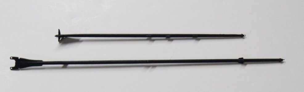
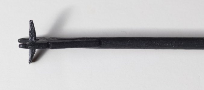
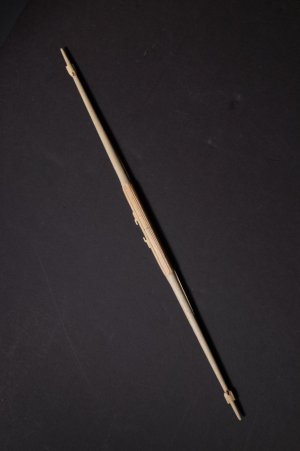
I also made 2 swinging lower studdingsail booms.
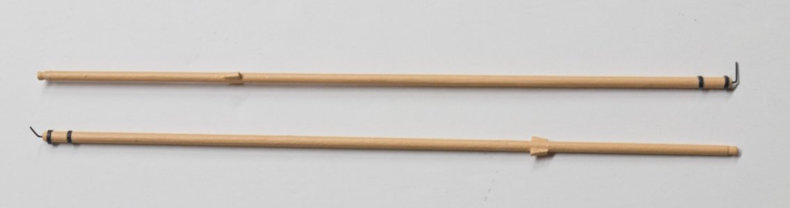
In order to break up the tedium of cutting and placing copper onto the hull, I worked on constructing the yards, boom and gaff. The octagonal parts of the bigger yards were made by gluing squares of strips around the yard and trimming and sanding down to the octagonal shape.
I made a simple jig to do the footropes, trying to get them even. The tan line was my target length. After I had the 2 end outer ones set, I ran a piece of piano wire through the loops to add weight another guide. I tied the rope to the yard and then around the wire and formed and tied the loop. This work better that just judging by eye which I have done in previous builds.
I also made 2 swinging lower studdingsail booms.
Helm / Ship's Wheel
Here's the ship's wheel nearly completed. I turned the drum between wheels on a mini lathe from a piece of dowel. I still need to complete the stands/supports.
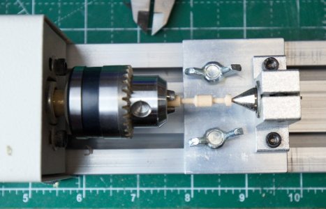
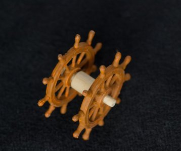
Here's the ship's wheel nearly completed. I turned the drum between wheels on a mini lathe from a piece of dowel. I still need to complete the stands/supports.


Good afternoon Jeff. I concur with the other guys. Your coppering came out great. Lovely progress all round. Cheers Grant
HI everyone. Thanks for your positive feedback. It definitely helps my motivation. I have the ship on hold for the time being after making too many nagging errors that needed to be fixed. (I am certain many of you know the type of errors I am talking about. Ones that were made not really paying attention to detail, attaching things improperly, etc.) I will attribute it to a bit of burn out. This is by far the most difficult model I have worked on to date.
Construction of the tops
The tops are fairly easy to make with the main flat part being provided as a laser cut piece. I wet and bent the front edging before gluing. The other 3 edges are just straight pieces. The cleats (probably a bit oversized) are made from plastic sheet. drilled with a pin for attachment.
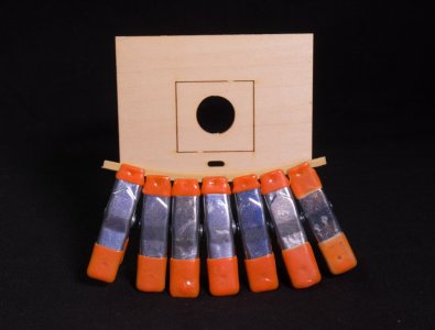
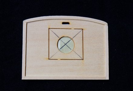
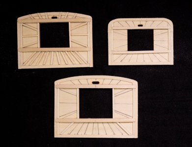
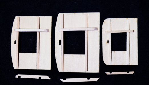
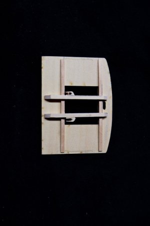
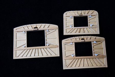
The tops are fairly easy to make with the main flat part being provided as a laser cut piece. I wet and bent the front edging before gluing. The other 3 edges are just straight pieces. The cleats (probably a bit oversized) are made from plastic sheet. drilled with a pin for attachment.
Crosstree construction
I bent the pieces for the crosstrees around a gallon paint can. This required doing the bending against the grain, so it was a bit more difficult, but the amount of bend was not too severe. I created a diagram for cutting the individual "arms" of the crosstrees marked for the assembly for each mast. Some thin wire was added to simulate the standoffs for the shrouds. I see from the pictures that the mizzen crosstree lost one of the wires that needs to be replaced.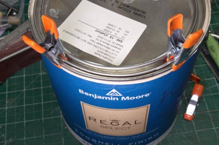
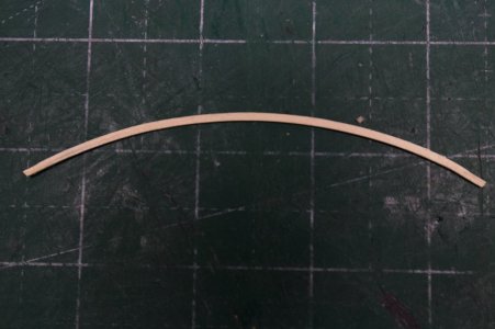
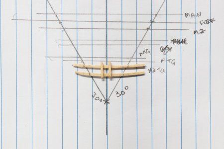
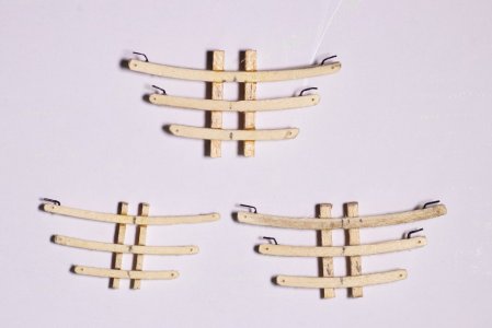
I bent the pieces for the crosstrees around a gallon paint can. This required doing the bending against the grain, so it was a bit more difficult, but the amount of bend was not too severe. I created a diagram for cutting the individual "arms" of the crosstrees marked for the assembly for each mast. Some thin wire was added to simulate the standoffs for the shrouds. I see from the pictures that the mizzen crosstree lost one of the wires that needs to be replaced.