
Lookin Good Kurt

You are using an out of date browser. It may not display this or other websites correctly.
You should upgrade or use an alternative browser.
You should upgrade or use an alternative browser.
Vasa - 1:65 DeAgostini [COMPLETED BUILD]
- Thread starter dockattner
- Start date
- Watchers 145

Thanks for checking in on this progress report. I am nearing the end of the first layer of hull planking (the stern remains) and while I suspect there is a collective yawn from those of you who have built many model ships I'm feeling a real sense of accomplishment. This has been a long hard slog and even though everything gets buried beneath the next layer of planking I still feel really great about how this build has been going.
.JPG")
It has taken all of my maturity to not start sanding. The irregular surface and voids are driving me crazy. But if I sand I will lose all my layout lines and I want to lay in the gun ports while I still know where I am...
.JPG")
.JPG")
Thanks for checking in!
It has taken all of my maturity to not start sanding. The irregular surface and voids are driving me crazy. But if I sand I will lose all my layout lines and I want to lay in the gun ports while I still know where I am...
Thanks for checking in!

wow, thats a neat looking planking job.
Very good doc, it will all sand and level out, especially with the ability to use filler. Just take your time and sight down the hull to make sure it’s true before the final plank.

Hi Paul!
You have produced a very beautiful, accurat hull with clean lines. Every model maker is happy with such a good result.
With best regards
Thomas
You have produced a very beautiful, accurat hull with clean lines. Every model maker is happy with such a good result.
With best regards
Thomas

No yawns here. This is a milestone and worth celebrating.
Last edited:
I have been pondering on buying this kit too! Vasa is a magnificent ship.
Very good work on the planking -> 
Hey Everyone, I'm looking for some help.
I am preparing to lay out and cut gun port openings in the primary hull. I looked ahead in the instructions and found this image.

Notice how the openings are vertically oriented and do not flow with the wales. This seemed off to me so I looked at some drawings I found on one of the Vasa Museum forums and if I am seeing things correctly the gun ports track with the curvature of the wales and are not set to a true vertical.

As far as I can tell DeAg has drawn the gun port openings parallel to the frames which is correct - but I don't think the frames ran vertical. I found the following and it would appear that the frames (yes, I realize the DaAg frames are not the same as found on the real ship) actually 'tip' along the length of the ship. See the following:

Am I completely lost here? If so, where have I gone off the rails?
And more importantly, if I am correct and I need to reorient the gun ports - how do I lay them out?
I am preparing to lay out and cut gun port openings in the primary hull. I looked ahead in the instructions and found this image.
Notice how the openings are vertically oriented and do not flow with the wales. This seemed off to me so I looked at some drawings I found on one of the Vasa Museum forums and if I am seeing things correctly the gun ports track with the curvature of the wales and are not set to a true vertical.
As far as I can tell DeAg has drawn the gun port openings parallel to the frames which is correct - but I don't think the frames ran vertical. I found the following and it would appear that the frames (yes, I realize the DaAg frames are not the same as found on the real ship) actually 'tip' along the length of the ship. See the following:
Am I completely lost here? If so, where have I gone off the rails?
And more importantly, if I am correct and I need to reorient the gun ports - how do I lay them out?
It seems, that the frames of the Vasa were really also following the deck-curve (and not rectangle on the keel)
-> this would mean, that the gunports are every time rectangle to the deck and with this also rectangle to the wales
.jpg")


also interesting sketches
 www.akg-images.de
but I am absolutely not an expert on the Vasa...... sorry
-> this would mean, that the gunports are every time rectangle to the deck and with this also rectangle to the wales
also interesting sketches
akg-images - Search Result
but I am absolutely not an expert on the Vasa...... sorry

Hi Doc,
For my 2cents the gun ports being radial or normal to the wale lines looks more pleasing to my eye. Simply running a small 90 deg square along the wales should be close enough.
For my 2cents the gun ports being radial or normal to the wale lines looks more pleasing to my eye. Simply running a small 90 deg square along the wales should be close enough.
Why look at drawings if you can check the real thing, thats the great advantage of building Vasa.Hey Everyone, I'm looking for some help.
I am preparing to lay out and cut gun port openings in the primary hull. I looked ahead in the instructions and found this image.
View attachment 183886
Notice how the openings are vertically oriented and do not flow with the wales. This seemed off to me so I looked at some drawings I found on one of the Vasa Museum forums and if I am seeing things correctly the gun ports track with the curvature of the wales and are not set to a true vertical.
View attachment 183891
As far as I can tell DeAg has drawn the gun port openings parallel to the frames which is correct - but I don't think the frames ran vertical. I found the following and it would appear that the frames (yes, I realize the DaAg frames are not the same as found on the real ship) actually 'tip' along the length of the ship. See the following:
View attachment 183883
Am I completely lost here? If so, where have I gone off the rails?
And more importantly, if I am correct and I need to reorient the gun ports - how do I lay them out?
See here a full 3d foto rendering of the real thing.
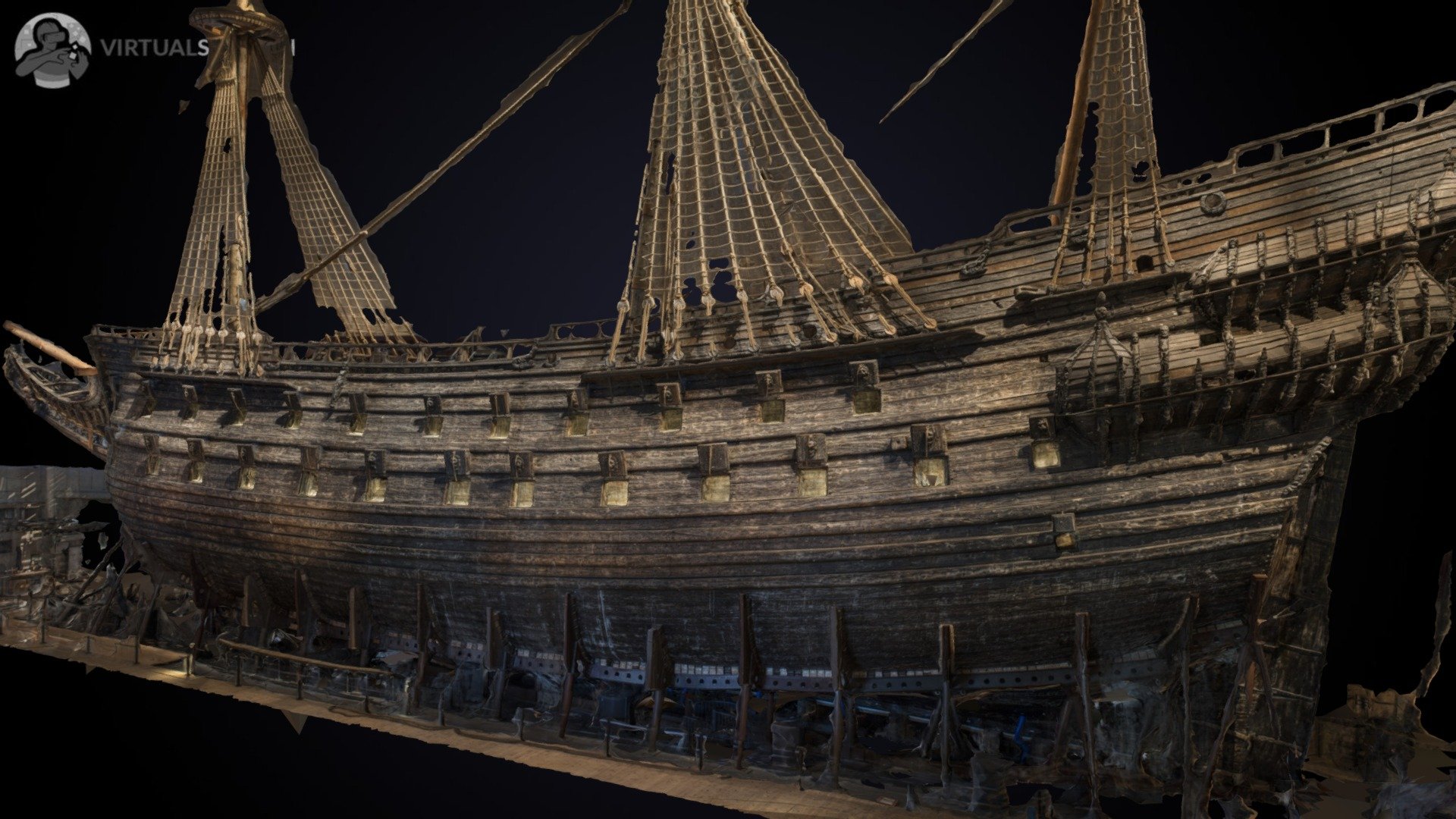
Vasa Ship - 3D model by Virtualsweden
Vasa (or Wasa) is a retired Swedish warship built between 1626 and 1628. The ship foundered after sailing about 1,300 m (1,400 yd) into its maiden voyage on 10 August 1628. This is a partial 3d model made with photogrammetry. - Vasa Ship - 3D model by Virtualsweden
 sketchfab.com
Vasa was build shell first, this means the frame sections were only fitted to the hull planks and were not build as individual frames. Therefore frames are not always vertically placed and as frames form the sides of the the gunports the dont need to be vertical. The top and bottom of the gunport follow the curvature of the deck, which is at Vasa nearly identical to the wales. The gunport being nearly square.
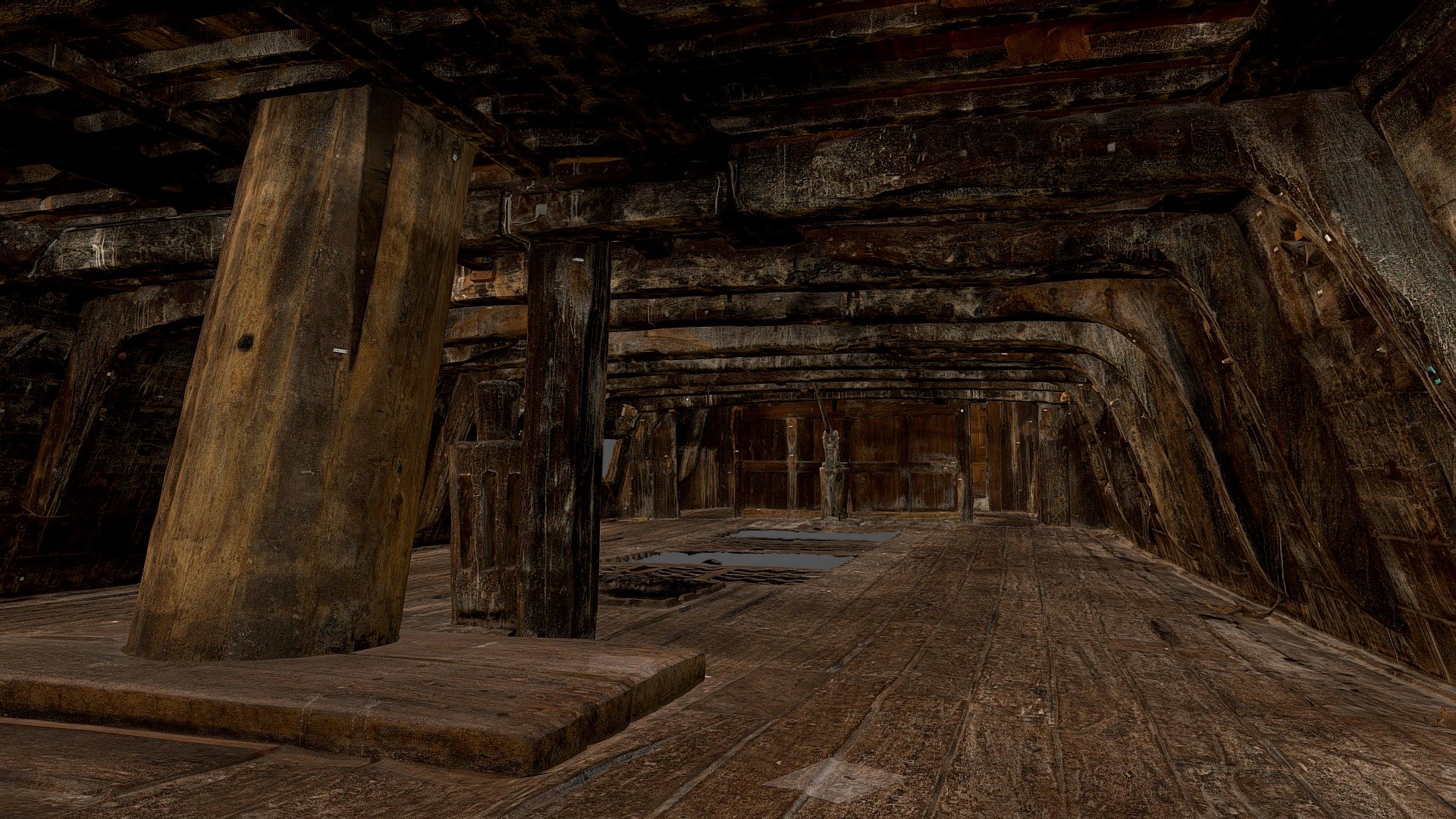
See below a picture of the inside of the upper gundeck at the most aft gunport, it follows the deck and is square.

Want to walk around the deck, see the 3d model below. You can actually walk around if you have a set of VR glasses.
Vasa, the upper gun deck - Download Free 3D model by SWEDISH NATIONAL MARITIME AND TRANSPORT MUSEUMS (@maritima)
Vasa is a Swedish warship built between 1626 and 1628. The ship foundered after sailing about 1,300 m (1,400 yd) into its maiden voyage on 10 August 1628. The model is made from 11500 photographs taken with a dslr camera and a ringflash. Since all parts of Vasa are covered with polyetylene...
sketchfab.com
Hope it helps.
Thank you Uwe. You may not be an expert but it turns out you are correct. As confirmed by Maarten the gun ports follow the line of the decking on the inside of the ship. I'm a landlubber so it never occurred to me that the gun deck would follow a curve longitudinally along the length of the ship. Thank you for your insight!It seems, that the frames of the Vasa were really also following the deck-curve (and not rectangle on the keel)
-> this would mean, that the gunports are every time rectangle to the deck and with this also rectangle to the wales
View attachment 183946 View attachment 183948
View attachment 183947
also interesting sketches
akg-images - Search Result
but I am absolutely not an expert on the Vasa...... sorry
Last edited:
Agreed Daniel. Not pleasing to the eye is what caught my attention when studying the picture from the instructions...Hi Doc,
For my 2cents the gun ports being radial or normal to the wale lines looks more pleasing to my eye. Simply running a small 90 deg square along the wales should be close enough.
Brilliant Maarten! The 3D model is just too much fun! BTW someone posted that a new improved version is coming soon.Why look at drawings if you can check the real thing, thats the great advantage of building Vasa.
See here a full 3d foto rendering of the real thing.
Vasa Ship - 3D model by Virtualsweden
Vasa (or Wasa) is a retired Swedish warship built between 1626 and 1628. The ship foundered after sailing about 1,300 m (1,400 yd) into its maiden voyage on 10 August 1628. This is a partial 3d model made with photogrammetry. - Vasa Ship - 3D model by Virtualsweden
Vasa was build shell first, this means the frame sections were only fitted to the hull planks and were not build as individual frames. Therefore frames are not always vertically placed and as frames form the sides of the the gunports the dont need to be vertical. The top and bottom of the gunport follow the curvature of the deck, which is at Vasa nearly identical to the wales. The gunport being nearly square.
See below a picture of the inside of the upper gundeck at the most aft gunport, it follows the deck and is square.
View attachment 184005
Want to walk around the deck, see the 3d model below. You can actually walk around if you have a set of VR glasses.
Vasa, the upper gun deck - Download Free 3D model by SWEDISH NATIONAL MARITIME AND TRANSPORT MUSEUMS (@maritima)
Vasa is a Swedish warship built between 1626 and 1628. The ship foundered after sailing about 1,300 m (1,400 yd) into its maiden voyage on 10 August 1628. The model is made from 11500 photographs taken with a dslr camera and a ringflash. Since all parts of Vasa are covered with polyetylene...
Hope it helps.
And thank you for confirming what Uwe suggested. The gun port being square to the deck will be my solution. See below...
- Joined
- Oct 29, 2019
- Messages
- 90
- Points
- 58

i will enjoy following the build !!The kit comes in 12 (monthly) boxes and each box contains the individually packaged stages that correspond to the build steps (detailed in the Assembly Guide on the Model-Space website).
View attachment 177760
The first thing I did was open the boxes and take a complete inventory. Did I have all the packages? It appeared that I did (oddly, one was labeled for the German market but that surely shouldn’t matter).
View attachment 177761
View attachment 177762
I then identified all of the cast metal/decorative pieces and removed them from the packages. To the extent that I could I tried to combine ‘like’ pieces into zip lock bags labeling each bag with the box it came from along with the build-stage. Inexplicably, for example, the lions’ heads for the gun port covers were found in more than ten different stages of the build...
View attachment 177764
View attachment 177765
While the Assembly Guide calls for simultaneous construction and painting this seems wonky to me (though it would spread out the meticulous painting obligation). I could not imagine building the false keel and frame elements over the course of months while also painting decorations along the way. It seemed better to gather all the pieces and build the ship in the same general flow as all the other builds I have seen on the forums.
As a novice I might regret this decision since it means I will not be following the DeAg build instructions precisely. Since my Roter Lowe instructions were in Italian 35 years ago and I only speak English I felt (foolishly?) emboldened to use the instructions as a guide rather than as dogma.
About half-way through the sorting I began to better appreciate the scope of what I was going to be attempting – there are lots and lots of parts – and there are lots and lots of metal bits – and lots of the metal bits are really tiny. How was I going to detail/paint something I could barely see? I held one of the little metal guys under a 1.5 magnifying lamp. Brighter! But still tiny. Maybe I need to start dialing back my expectations!
So, that's the story of my prep work... Next post will happen when I have something to show. Thanks for checking out this new forum!
So, here is what I came up with...
Based on my research and supported now by what was shared above I will endeavor to align/orient the gun ports with the wales.
In a stroke of luck I had previously marked the lower gun deck on the hull of the ship. I did some calculations and determined that the bottom of the lower line of gun ports should be placed 11mm above the lower decking. That converts to around 28 inches to scale (for those who live in the rest of the world you'll need to convert to metric if interested...).
I then simply laid out the openings...

I added the upper row of gun ports as well. If you are concerned that the spacing between the gun ports is irregular that is not a mistake on my part (heaven knows I have made, and will continue to make, lots of mistakes - but not this time!). A careful review of the drawings above (or, of course, a look at the original ship) reveals that the port holes were inconsistently spaced. How unexpected for his majesty's prize ship!
And here are my first few attempts at cutting holes in the side of my ship .
.


Only time will tell if I regret doing the gun ports now instead of waiting until the second planking and precise placement of the wales!
Onward! And thanks so much for your help!
Based on my research and supported now by what was shared above I will endeavor to align/orient the gun ports with the wales.
In a stroke of luck
I had previously marked the lower gun deck on the hull of the ship. I did some calculations and determined that the bottom of the lower line of gun ports should be placed 11mm above the lower decking. That converts to around 28 inches to scale (for those who live in the rest of the world you'll need to convert to metric if interested...).I then simply laid out the openings...
I added the upper row of gun ports as well. If you are concerned that the spacing between the gun ports is irregular that is not a mistake on my part (heaven knows I have made, and will continue to make, lots of mistakes - but not this time!). A careful review of the drawings above (or, of course, a look at the original ship) reveals that the port holes were inconsistently spaced. How unexpected for his majesty's prize ship!
And here are my first few attempts at cutting holes in the side of my ship
.Only time will tell if I regret doing the gun ports now instead of waiting until the second planking and precise placement of the wales!
Onward! And thanks so much for your help!
Last edited:
Thats always a time consuming and monotonous job cutting out the gunports. Looking good.
Hi Paul!
You have made the right decision.

Source: W. zu Mondfeld, Wasa, Schwedisches Regalschiff von 1628, Mosaik Verlag, Architectura Navalis.
The photo is somewhat distored, but still shows the tilted bulkheads towards the main mast. The Vasa was built as a bowl shape. First the keel, then the planks of the underwater hull and only then the frames were inserted diagonally.
With best regards
Thomas.
You have made the right decision.
Source: W. zu Mondfeld, Wasa, Schwedisches Regalschiff von 1628, Mosaik Verlag, Architectura Navalis.
The photo is somewhat distored, but still shows the tilted bulkheads towards the main mast. The Vasa was built as a bowl shape. First the keel, then the planks of the underwater hull and only then the frames were inserted diagonally.
With best regards
Thomas.
Last edited: