Vasa Build Log - Billing Boats - Scale 1/75 [COMPLETED BUILD]

Paul,

Referencing your Point 2, this was an error in my upload version. My starting point was the museum's diagram, which of course had the pin rails on the bulwarks. My later edition (which I have updated Post #259 and upload again here as a PDF), had these belay pin rails removed. It is not as simple as merely moving the indicated locations to the cap-rail, since between the two Belaying Plans, there is a discrepancy which relates to the location of the Mizzen Bowline. This is located (as the central pin of the replaced pin rail) in the museum's plan, but does not occur on the Stolt Rigging Plan. I have taken the liberty of adding it for consistency as it is needed and obviously has to be secured somewhere. Please feel free to download and use the updated version of the plan.

Referring to your first point, the Crojack Yard Brace and the Mizzen Topsail Brace belaying points near the stern are a little confusing. If we go to various other modellers interpretations, I like the Janssen model which shows the Mizzen Topsail Brace coming back to be secured under the top railing (presumably to a cleat or point inboard), and the Crojack Yard Brace probably to an eyebolt on the after deck (see below).
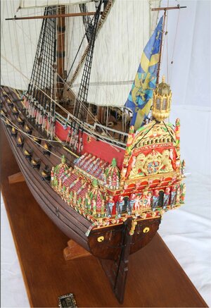
Rear_Detailed_Accurate_3.jpg

On the Corel model by Michael (md1400cs), he uses two belaying pins through the LOWER railing along the bulwarks of the afterdeck. This to me seems a much simpler and better solution, but at the end of the day, even Fred Hocker is unlikely to know with any certainty where these two belay points are located. Personally I lean to Michael's solution (see below), but then, if you look forward along the same railing on his model, he has placed additional belaying pins, where the Belay Plan does not say there are any:
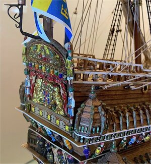
Crojack.jpg

Yet another interpretation comes from Frank (fmodajr) where he merely secures the lines to the vertical railing supports (see below). I am not an advocate of this approach, as I don't think this would be a solution for a real ship.
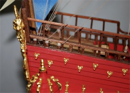
Crojack_1.jpg

Welcome any other ideas...

PeterG
 

Attachments

Last edited:
Paul,

Referencing your Point 2, this was an error in my upload version. My starting point was the museum's diagram, which of course had the pin rails on the bulwarks. My later edition (which I have updated Post #259 and upload again here as a PDF), had these belay pin rails removed. It is not as simple as merely moving the indicated locations to the cap-rail, since between the two Belaying Plans, there is a discrepancy which relates to the location of the Mizzen Bowline. This is located (as the central pin of the replaced pin rail) in the museum's plan, but does not occur on the Stolt Rigging Plan. I have taken the liberty of adding it for consistency as it is needed and obviously has to be secured somewhere. Please feel free to download and use the updated version of the plan.

Referring to your first point, the Crojack Yard Brace and the Mizzen Topsail Brace belaying points near the stern are a little confusing. If we go to various other modellers interpretations, I like the Janssen model which shows the Mizzen Topsail Brace coming back to be secured under the top railing (presumably to a cleat or point inboard), and the Crojack Yard Brace probably to an eyebolt on the after deck (see below).

View attachment 248966

On the Corel model by Michael (md1400cs), he uses two belaying pins through the LOWER railing along the bulwarks of the afterdeck. This to me seems a much simpler and better solution, but at the end of the day, even Fred Hocker is unlikely to know with any certainty where these two belay points are located. Personally I lean to Michael's solution (see below), but then, if you look forward along the same railing on his model, he has placed additional belaying pins, where the Belay Plan does not say there are any:

View attachment 248968

Yet another interpretation comes from Frank (fmodajr) where he merely secures the lines to the vertical railing supports (see below). I am not an advocate of this approach, as I don't think this would be a solution for a real ship.

View attachment 248969

Welcome any other ideas...

PeterG
I’m by no means an expert, however I can offer my opinion. Given most running lines are belayed with pins or cleats… if it were my ship and left to interpretation, I would either add cleats to the inboard side of the rail uprights…or I would add the belaying pins to the lower rail.
Only if it is standing rigging, would I opt for eyes on the deck, in an appropriate location.
Hope I’m not being rhetorical. ;)
 
I am inclined to agree with you Dean, hence my leaning towards Michael’s (md1400cs) where he uses belaying pins above the mid railing along the stern bulwarks.

Now, I have another ‘interpretation’ rigging question for you…. We know that for this era of ship, a series of ‘crows feet’ are used to strain various lines eg stays, backstays and to the aft most shrouds of the lower main mast. Within the body f the ship, I have two shroud crows feet, two stays (for the mizzenmast and main stays), backstays of the fore gallant. Each crows foot rigging I would refer to as ‘fixed’ rigging as opposed to running rigging, but they all have two or three blocks, with multiple lines going to the stay/shroud.

My question is, ‘Where are the straining lines that are attached to crows feet belayed?’ It is not on the rigging or belaying plans, and it would be something a crew would need to adjust while sailing.

Most models I have reviewed appear to belay these lines with belaying pins on the cap rail, but if this was the case, then they should be indicated in the Rigging Plans. Additionally, the majority of crows feet are attached along the ships centreline with the stays or backstays. As such, to be belayed above the bulwarks to belaying pins, the line would have to cross to the outside of the ship, which would pull the stay off centre - that doesn’t sound right. So, my solution would be to have some deck eye bolts near the centreline where they could be secured.

What do others think?

PeterG
 
My apologies to those who like to keep up with posts on a Build Log. I have been making some progress, but it has been slow with Covid lockdowns and having to do some actual money-making work!! I am at the point now where I have effectively completed the standard, fixed rigging. I have been battling with crows feet and still don't have them perfected. Getting the tensions right on such a large number of lines is very difficult. The best method I have been able to come up with is get the tensioning about right, strain the stay (to which the crow feet lines are attached), apply watered-down PVA glue, allow to dry, and then remove the tension. This allows the stay to return to be relatively straight and undistorted by the crow feet. I suspect that some bending of the stay is inevitable but at least it is minimised.

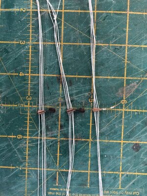
In the crows feet development too, I have found that my making of euphroe blocks has been largely affected by the direction of the wood grain in their construction. To make the shape, I have cut it roughly, drilled the necessary holes, and then filed the edges and ends to be rounded. The problem I found was that with the grain running the length of the block and the drilled holes being close together, when the crow feet lines are passed through and tension applied, the grain was giving away, and allowing consecutive lines to break into the next lower hole etc. The way I found around this, was to make the blocks with the grain of the wood across the length of the euphroe block, so the strength between the adjacent holes was increased substantially. This made the blocks harder to make in terms of shaping and edge sanding, but much stronger between the holes and along the length of the block. I attach a couple of photos of the standing rigging as it developed.

Below are some euphroe blocks with crow feet lines pre-threaded and ready for attaching to their supporting lines.

IMG_8249.JPG

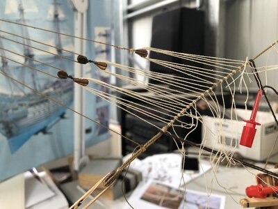
And here are the bow forestay crow feet. I have used Clove Hitch knots for all joints of the crow feet lines to the stays. In the example below, I have added tension lines to the forestay to keep it relatively straight while I add PVA glue to lines to keep them more-or-less with a fixed tension.

IMG_8252.JPG

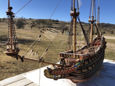
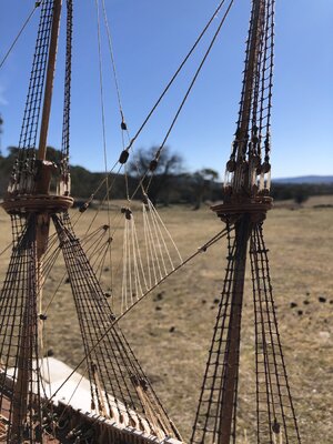
Here are a couple of overall images of the ship with the standing rigging virtually complete. There is some cleaning up of loose lines and shortening/securing of lines to be done on deck, but overall it has come together quite well. In some of the stays with crow feet attachments, you will see the distortion applied by the crow feet tensioning. I have a couple more applications of tension and gluing to do to try and reduce this.

IMG_8315.JPG


IMG_8320.JPG

My photography skills are lacking (using an iPhone). I should get the SLR camera out and try to improve the detail in the photos. Photographing model ships well is quite an art in itself. I know there is a section on SOS to assist with this so I will try and read up on it to improve the depth-of-field and an appropriate backdrop to allow the lines of various colours and thicknesses to be better seen.

From this stage, I am up to investigating sails and getting them prepared for the ship. I have commence a bit of background research and there appears to be a myriad of different methods. I have reviewed a number of sources, mainly from the museum which documents the sinking and at that time, there appears to only be FOUR sails set when she went down. There are 11 sails in total, so I have decide on the 4 to be prepared and set which:

a) saves me a LOT of sail preparation time
b) still allows for a good display of deck detail, rigging etc but
c) allows for running rigging to be seen on the sails hoisted which for unfurled or non-set sails, would not be available (eg clew lines, buntlines, leechlines etc etc.).

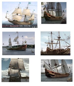
Below are pictures of the Vasa from various of the numerous videos of her sinking. It shows clearly the four sails which were set when she sank. These are:

- the Lower Foresail,
- Fore Topsail,
- Main Topsail and
- Mizzen (Lanteen) sail.

Sails_Set.jpg

Interestingly, the Mainsail appears to also have been furled, but on its spar, so I will probably try and do this too. None of the Topgallants or Spritsails appear to have been added or furled.

Elapsed Time: 2165 Hrs (with a lot of extra time taken on the standing rigging that I wasn't expecting - It is SLOW.....)

PeterG
 
Really interesting photos Peter. I can only see two ways to eliminate distortion along the mainstays.
1. Run the crows feet slack which to me would be undesirable.
2. You would have to add tension of equal value in the opposite direction which would call for additional (permanent) rigging apparently not shown anywhere.
I would imagine the amount of tension needed on the mainstay to overcome the crows feet pull would probably distort the fore and mainmast out of plumb.
I will be watching for your solution so I can copy it! Your overall rigging looks great by the way.
 
Thanks Daniel for your suggestions. In the end, a few additional doses of watered down PVA glue while the crows feet are under tension, ie stretched, wait until dry then release tension, appears to have done the job.

Now, moving on. Since my last post, I have been investigating sails. I think I have uncovered a can of worms. Sewing, fabrics and all the intricacies of it appear to be the domain of the fairer sex and so my knowledge of fabrics etc is NIL, let alone sewing and shaping fabric. In the next few posts, I will try to explain the road I have taken. I could NOT have done this alone - my wife (The Admiral) has been so supportive and helpful, I am in awe of her talents. So here goes.

As I said in the post #264, I am intending to only use the sails of the Vasa as she was thought to have set at the time of her sinking. These are:

- the Lower Foresail,
- Fore Topsail,
- Main Topsail and
- Mizzen (Lanteen) sail.

Plus I will rig a cut-down version of the mainsail which then shows a furled sail but doesn't hide the rigging or deck space.

CHOICE OF FABRIC

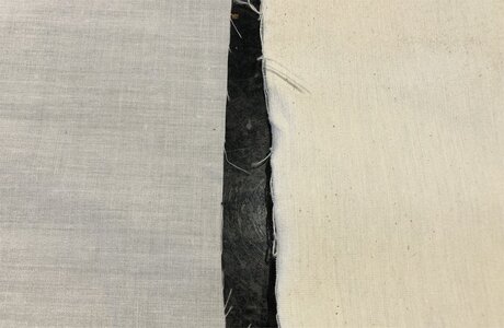
The choice of fabric was one initially made by Billing Boats and the Vasa kit. Sufficient material was supplied in the kit, but it was a relatively heavy, almost parchment like material. I felt it would have appeared too thick and difficult to work with. The Admiral also made the comment that to turn hems and seams along the sail edges with this material would require quite heavy duty needles and sewing machine. So, off to the fabric shop we went.

Below you can see on the right, the kit supplied sail material and on the left, a relatively light, whiter, close knot calico. This image is as close as my iPhone will go and still focus, so from a viewing distance, the lighter material should be OK.

Image1.jpg

So, with the fabric secured, we then had to experiment with colouring/staining the cloth.

TEA OR COFFEE ANYONE?

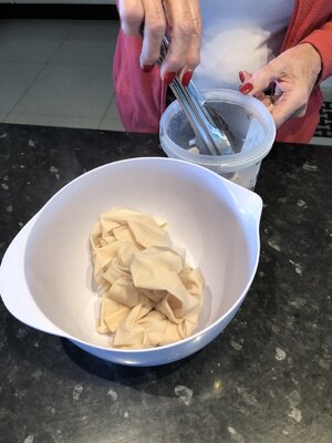
The fabric as shown is way too white, and so required darkening to get a better, somewhat aged look, despite it representing the first sailing of the new ship. I have read a number of builders have used both tea or coffee to colour their sails. Other dyes have also been used (eg Rit), but these tend to be too strong and make the sails too dark (unless that's the colour you may be seeking (eg Black Pearl). We decided to brew up a bowl of tea (one Twinings Early Breakfast tea bag in about 500mL of hot water), and some coffee. The coffee using coffee grounds from 'real' coffee did not work as we found minute grounds of the coffee still came through and discoloured the fabric. So, we used a teaspoon of instant coffee, again in about 500 mL of hot water.

IMG_8328.JPG

You cannot judge the colour of the finished product until its dry. Above you can see the fabric, cut to size for the sails but immersed into the tea mix. After drying, my preferred colour was from the tea. The coffee mix worked fine, but it seemed for my application, to be too deep a brown.

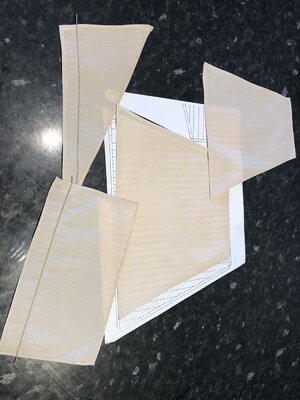
The sail patterns provided in the plans of the Billing Boats kit are clear and easily used as a template. I photocopied the relevant sails at 1:1 size and used the copies, so I didn't hurt the original plans. I laid out the template under the cloth, and using a 'heat invisible' marker pen, copied the edges and seam positions on the fabric. These pens come from a hardware or fabric shop and in two types - They either turn invisible when ironed (heat treated), or when washed (water treated). The former was preferred in our case as I didn't want the sails washed after being sewed and coloured.

The next post will be the next stage of my 'sailing adventure'.....

PeterG
 
NEXT SAIL INSTALMENT

With all the templates and coloured sail material available, I overlaid the fabric over the individual sail shapes and cut them out. It is important that the web and warp of the fabric lies parallel to the vertical seams (I only just learnt about this from The Admiral). It makes sense though because, when you think about it, if the edges aren't vertical, the threads tend to unravel and make a mess with loose threads.

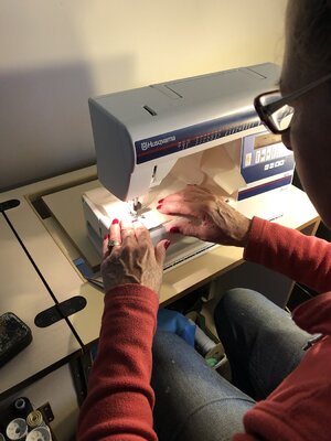
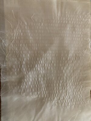
I have marked the fabric with my 'invisible marker' pen (see previous post), along all the seams and the edges. So now the sewing could commence. It was important with this that the sewing pattern be of the correct tension and I wanted a small thread pattern to simulate the seams on the real ship. This took a lot of experimentation, swearing by The Boss, and adjustment. In the end we never really got this right and the fabric tended to 'bunch' the material and cause wrinkles.

IMG_8329.JPG

The wrinkles where a major issue. Below is a picture of the Foresail where there are a LOT of vertical seams which strongly pull the fabric.

IMG_8340.JPG

About the only way I was able to overcome this, was the pull the fabric along the line of the seams, re-iron, pull seam, re-iron LOTS of times. Eventually, the wrinkles worked their way out (or the threads expanded and were pulled in), but the final result was a relatively 'flat' sail, which was not too distorted by the sewing. Ironing at a hot setting, but with a Rayon cloth over the top to prevent too much direct heat was essential - Again, The Admiral's experience came through...

PeterG
 
SAILS AGAIN

With the sail material seams sewn vertically through the sails required, it is then time to properly cut the sizes and do the edges (hems). Cutting the sails to the right size is not an issue as the paper copy templates serve that purpose, but a mistake I made was to cut the fabric size too close to the marked outline of the sail. Each template defines the sail edge, PLUS a distance for the hem to be folded over. However, to do the hem properly, the fabric edge has to be folded over, and then tucked under again before being sewn. To ensure the hem fold stays put, it has to be ironed to retain the fold. Importantly however, when you think about it, the fold over (so the fabric edge is tucked within the hem), has to be folded TWICE, once for the edge to be folded in and a second time so the edge is within the hem before sewing. This process requires quite a lot of the fabric to be left around the outside, before the hem fold is made and is in fact, three times the width of the hem size to edge the sail to the template marking.

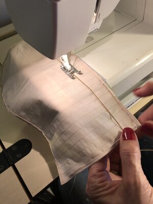
Within two of the sails too, there is a 'rope' which is required to be inserted and sewn into the sail. This is for reefing the sail and forming a 'bonnet' used for when the sail is furled, but also to increase the size of a sail so that it is strengthened and allows more wind to catch the sail. Below is a picture of the bonnet rope being sewn into the sail. The position of these ropes was marked on the sail plans. Not all sails had the bonnet. In my case for the four I have planned on, only the Top Foresail and the Mizzen.

IMG_8335.JPG

In the picture above, you can see the edge hems completed while the bonnet rope is being sewn along the lower portion of the sail. This sail is the Top Foresail. The finished sail is shown below.

IMG_8339.JPG

Only four more sails to go!!! The making of sails is fraught with issues. While I was imagining it would not be too difficult, I am soon learning otherwise. The ship at this time is not getting ANY attention so I hope the sailmaking effort is worth it.

As an aside (and one which gave me some inspiration), a Russian video on sailmaking for model ships (primarily using glue) and in a great Build Log here on SOS. It is well worth a look.

Regards,

PeterG
 
Last edited:
I like your solution to the tensioning of crows feet without distortion of the stays. Thank you. I'm a ways off for making sails but will bookmark yours and your admirals effort.
 
Thank you Uwe and Daniel. Complimentary comments are always welcome!! We are so lucky here to have three or four active builders constructing the Vasa and with such great Build Logs being created. There have been many in the past too, but everyone has a different 'take' on the same challenges and it always amazes me how inventive and clever people are to come up with new solutions.
 
Continuing with the sails. After a successful approach with the Top Foresail, we moved on using the same principles to the other four sails. In the case of the Mainsail, this is intended to be furled and as discussed and described by other builders, for furling a sail, it looks neater and presents better when only about 2/3 of the proper sail's height is used.

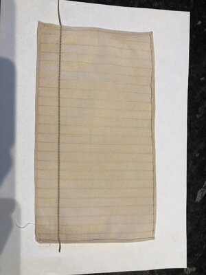
This method of furling a sail for presentation was described in detail by Frank (fmodajr) as well as partially set/furled sails on the 1/10 museum model. Below are the various sails all sewn with seams and hems folded over and sewn.

For each sail, after seams were sewn, the ironing process was required to get rid of the wrinkles (see previous post), the edges were then folded over about 1 cm, re-ironed and over again and re-ironed. This ensured the fabric edge was rolled into the hem before hem sewing around the edges. It is a bit tricky at the corners, especially on the sails with acute corner angles. Right angles and angles that are nearly 90 degrees are a lot easier. Some trimming of material for overlap and a neat hem are required.

IMG_8342.JPG

The next challenge involved the small pieces of fabric that are used as reinforcement on the edges of the sails where the leechlines are joined. If you look at most sailing ships, there is a double or triple 'patch' sewn into the sail which gives it strength for these lines to be used. I cut the patches to a scaled size and tried gluing to the edges of the fabric. To get this right (on some test edge fabric) was nearly impossible. I tried with CA (and got a solid, hard, plank of fabric). Tried with GS Hypo cement and this worked but seemed to darken the colour of the fabric compared to the sail fabric.

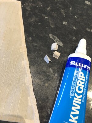
Looking at the Russian video on sailmaking for model ships, he used what is called 'carpet glue' or aliphatic glue. It's supposed to be similar to PVA but stronger and flexible. I tried to get some but no luck as noone would send it through the mail (and we are in Covid lockdown), so nowhere was close. Then I did a bit more research and found that a new type of glue (new to me anyway), was a Contact Adhesive which is WATER-based. Our local hardware store had some in a 200gm tube, cheap as chips ($6.00), and it goes on white, can be diluted, dries clear and with the aid of a hot blow-gun or hairdryer, set and dried quite quickly. For our local folk, this stuff is made by Selleys and called KwikGrip, but I am sure you could get it overseas.

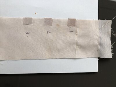
I needed to experiment with some patches to get the right combination of glue amount, pressure to apply, time to let the contact adhesive set and below I show a series of 3 patches applied each with different combinations to get the best result.

IMG_8341.JPG

Patch No 1 used glue applied to both sail and patch. It overdid the volume and marked the sail.

Patch No 2 applied glue to the patch only and while it worked, the glue oozed out the side when applied and made a mess.

Patch No 3 used only a small amount of glue sparingly around the margins of the patch and then applied. It worked well and seemed the best method. Note that any loose bits of fibre around the edges can be peeled or cut away after the glue sets.

IMG_8343.JPG

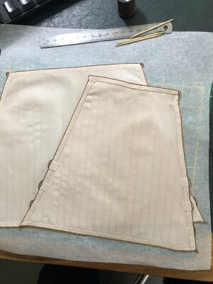
The best method I found was to cut the small reinforcing material but DOUBLE the length so it is big enough to wrap around the sail’s edge. With these, I folded in the middle and then iron them to form two sides that could be glued to both the front and back of the sail and wrapped around the hem (at the appropriate spots). I then applied the glue sparingly, only to the reinforcing bits (while holding them open with a toothpick). I let it dry for a few minutes, then slid them onto the hem of the sail. Pressing down with fingers and a tissue, gave me a neat, attached, clean reinforcing patch on both sides of the sail.

We are getting to the final stage of sail making - Only the perimeter bolt ropes to be added.

Regards,

PeterG
 
Last edited:
Thank you Paul. I only wish your build was ahead of mine - It is settings such a high standard!!!

I have now basically completed the sails. The last phase was to add the boltropes around the hems. While this is not hard, it was time consuming. Below are a couple of the finished product. The topmost sail in this picture is looking from the hem (aft) side or back of the sail, whereas the underlying sail is the frontside. I have added the boltrope by gluing the pre-made rope (which I think is about the right scale). I have not sewn the boltrope to the sail, but I am still thinking about this. Instead, I have used the water-based contact adhesive. The clear, matte adhesive I have used along the boltrope-to-sail edges seem to be holding well with suitable flexibility for shaping the sails. Sewing of the boltrope at this stage I hope is not necessary but I will fix the sails to a yardarm to see if I need to sew them around the hem/boltrope.

IMG_8379.JPG

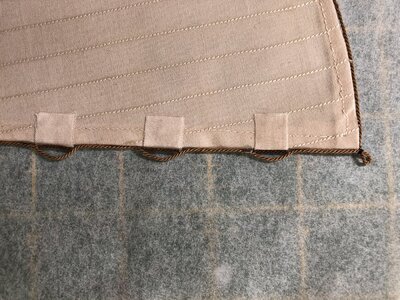
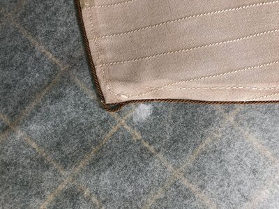
Note too in the picture above, you can see near the base of each sail (but only for appropriate sails as not all have them), the folded small patches of reinforcing around the hems. For each reinforcing patch, I have extended the boltrope out from the sail edge, which gives the leech line attachment points. The photo below shows this in greater detail. The boltrope simply extends out in a shallow loop, and then after attachment, a small length of boltrope is glued inside the loop against the hem to simulate the boltrope going right through continously.

IMG_8381.JPG

Also shown in the picture above, is the lower corner point of the sail. This is the boltrope extended out from the corner, then looped tightly with some whipping line to close the loop and make a clewline anchor point. The clews and clewlines will be attached to these corner loops.

At the top corners of the sails (where they attach to the yards), another boltrope extension is made but it is not tied off with thread. It is shown below.

IMG_8380.JPG

For these corners, the boltrope loop will be the anchor point with line attach to the end of the yard. Again, I have added a small bit of the rope to the inside of loop, against the hem, to simulate the boltrope going straight through.

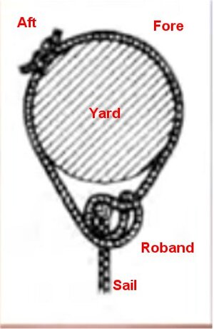
The attachments between the sails and the yards, going across the length of the yards are called robands. The robands can use a range of knots to attach the sail, but the one I am going to use is as shown below:

Roband.jpg

The robands line is to go through a small hole punched in the sail on its top edge. As I am doing this, I will show more detail in the next post.

Regards,

PeterG
 
Last edited:
Hi Peter, you have there some of the better looking sails I've seen yet. For some reason (to me) sails do not lend themselves to model reproduction very well. I really like the brown boltrope. My admiral does not sew but we do own a sewing machine so I can picture sewing my fingers into the sails which might give them a battle scared look!!:oops:
 
Daniel,

I like that - “a battle scared look”. I think you mean “a battle scarred look”. Sewing has been only a relatively small part of the process (although my wife would not agree)!!

The bolt rope has taken a long time and just getting all the wrinkles out was also time consuming. I am pleased I am only dealing with the four sails the Vasa had set when she sank. To do all eleven sails would be a much greater challenge and of course you face the age-old argument that sails “hide” the rigging and deck detail. The upside of having sails of course is that the true running rigging (clew lines, buntlines and leech lines) can be deployed, whereas these are not present (at least in their used position) if the sails are not set - Hence my decision to only set the four she sank with. This then is the best of both worlds, indicating how the sails were rigged but without too much detail being hidden by a full set of sails.

PeterG
Ha! Hi Peter,
Nice catch on the scared, scarred usage. I think they both would apply however I did intend scarred. I totally agree with the 4 sail (not sell) arrangement and that is what I will do as well. The 6 pictures from your post #264 are really going to be helpful when the time comes to set up my sails.
 
Paul,

Referencing your Point 2, this was an error in my upload version. My starting point was the museum's diagram, which of course had the pin rails on the bulwarks. My later edition (which I have updated Post #259 and upload again here as a PDF), had these belay pin rails removed. It is not as simple as merely moving the indicated locations to the cap-rail, since between the two Belaying Plans, there is a discrepancy which relates to the location of the Mizzen Bowline. This is located (as the central pin of the replaced pin rail) in the museum's plan, but does not occur on the Stolt Rigging Plan. I have taken the liberty of adding it for consistency as it is needed and obviously has to be secured somewhere. Please feel free to download and use the updated version of the plan.

Referring to your first point, the Crojack Yard Brace and the Mizzen Topsail Brace belaying points near the stern are a little confusing. If we go to various other modellers interpretations, I like the Janssen model which shows the Mizzen Topsail Brace coming back to be secured under the top railing (presumably to a cleat or point inboard), and the Crojack Yard Brace probably to an eyebolt on the after deck (see below).

View attachment 248966

On the Corel model by Michael (md1400cs), he uses two belaying pins through the LOWER railing along the bulwarks of the afterdeck. This to me seems a much simpler and better solution, but at the end of the day, even Fred Hocker is unlikely to know with any certainty where these two belay points are located. Personally I lean to Michael's solution (see below), but then, if you look forward along the same railing on his model, he has placed additional belaying pins, where the Belay Plan does not say there are any:

View attachment 248968

Yet another interpretation comes from Frank (fmodajr) where he merely secures the lines to the vertical railing supports (see below). I am not an advocate of this approach, as I don't think this would be a solution for a real ship.

View attachment 248969

Welcome any other ideas...

PeterG
Peter,
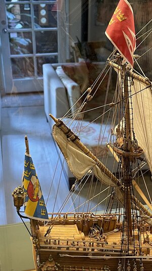
I'm way behind just catching up - maybe these two images might be useful

IMG_2875.jpegIMG_2876.jpeg
 
Peter,
Your ship is looking super!! Your rigging and sails are so well done. Your exterior images are superb. Yoru Vasa is "way up there" Thumbsup

Regards,
 
Many thanks @oldflyer, coming from you, that is compliment indeed!!!

Daniel, those photos came from screen grabs of some documentary film made by the museum plus some external researcher’s work. As such I am considering them as reasonably accurate and define the sails required.

Still moving forward but it’s taking about one day for each sail to bend to the yard. I’ll update with some pictures soon.

PeterG
 
Back
Top