Vasa Build Log - Billing Boats - Scale 1/75 [COMPLETED BUILD]

Stuart Little, the Vasa manual and instructions can be accessed from the Billings website or with the link,

https://www.billingboats.com/compon...582675740_1508915288-bb490-wasa-main-plan.pdf

Billings Boats have evidently upgraded their site content.

I guess all kit makers are well aware of the costs of quality inclusions for such things as blocks and anchors. Extruded plastic would always be cheaper than timber, but mass production I guess would obviously be cheaper but lacking in the detail many of us crave.

Interestingly I am currently looking at 3D printing some items such as cannons and blocks etc. You can hide a lot of plastic with a good paint job but if the detail can be created, it’s not a bad solution.

Regards

PeterG
 
Peter,
Indeed I think that 3D printing "correct" cannons will become a big part of many builders choices. As you know Billings, and others just fill their kits
with the same parts bin cannons. Yes a good coat of airbrushed paint would be excellent since many of us paint kit provided brass cannons black.

PS: I used Billing's rigging sheets for adding sails to my Corel Vasa - excellent outcome.

Regards,
 
John,

The Billings sail plans are quite good, as are their rigging plans, but used alone, for the detail I was searching for, it was not enough. I have also used Anderson, the museum plans extensively plus other research papers and plans.

The 3D printing option is an interesting area. I have found many 'free' STL format files which, when using a Slicer program such as Cura, you can then export G Code which is the machine instruction language for 3D printers. These are becoming relatively cheap, especially for the hobbyist, but to do the end product well, you have to indulge a significant amount of time to learn a 3D creation software package (such as FreeCAD or Fusion 360). These programs are quite sophisticated and while simple things can be generated relatively quickly, to generate the detail we are searching for, there is considerable additional time required.

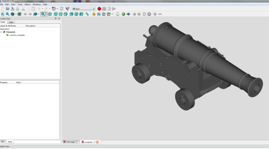
As an example, see below a picture of a ship cannon from a source called 'thingiverse' (a repository of STL format 3D objects, some useful, most not!!). Although it may look quite good, this is made up of about six parts, each requiring individual 3D printing, etc etc. Also, it may not contain suitable detail or require some modification at a small scale to replicate the cannon markings or fine features you are looking for. That said, with the knowledge to use the CAD software, you can modify and add this detail - It just takes a long time.

1658293839308.png

Items like cannons, anchors and even blocks and sailors/crew should all be achievable, and you, John, are correct, it is likely to be an area that is expanded and made more useful for us ship modellers.

It's probably a bit like 'making rope'. It is part of the overall hobby of ship building but many don't want to take it on, rather buying the upgraded product for their models, and that is fine.

Personally, I like to investigate these 'side' projects as part of the ship building hobby, but it's not for everyone.

Regards,

PeterG
 
Peter,

You are indeed "up there" with using technology Cheers indeed.
The Vasa II book is almost 5 years behind its original publication date> That book is intended to be the definitive work regarding Vasa
standing and running rigging. Still waiting. My understanding is that delays had to do with Swedish politics..... but have since been resolved

here is the latest - from the Vasa site and in responce to JanV's question in Feb. 022;

Dr. Fred Hocker has informed me that Vasa II is currently with the publisher, but due to complications arising from Covid-19 and world shortage of printing paper, the book is held up. We hope that it can be printed at the beginning of the summer and released in the autumn.

Here is a link from Dr. Fred Hocker with intended contents of the second book;

 
John,

The Billings sail plans are quite good, as are their rigging plans, but used alone, for the detail I was searching for, it was not enough. I have also used Anderson, the museum plans extensively plus other research papers and plans.

The 3D printing option is an interesting area. I have found many 'free' STL format files which, when using a Slicer program such as Cura, you can then export G Code which is the machine instruction language for 3D printers. These are becoming relatively cheap, especially for the hobbyist, but to do the end product well, you have to indulge a significant amount of time to learn a 3D creation software package (such as FreeCAD or Fusion 360). These programs are quite sophisticated and while simple things can be generated relatively quickly, to generate the detail we are searching for, there is considerable additional time required.

As an example, see below a picture of a ship cannon from a source called 'thingiverse' (a repository of STL format 3D objects, some useful, most not!!). Although it may look quite good, this is made up of about six parts, each requiring individual 3D printing, etc etc. Also, it may not contain suitable detail or require some modification at a small scale to replicate the cannon markings or fine features you are looking for. That said, with the knowledge to use the CAD software, you can modify and add this detail - It just takes a long time.

View attachment 319360

Items like cannons, anchors and even blocks and sailors/crew should all be achievable, and you, John, are correct, it is likely to be an area that is expanded and made more useful for us ship modellers.

It's probably a bit like 'making rope'. It is part of the overall hobby of ship building but many don't want to take it on, rather buying the upgraded product for their models, and that is fine.

Personally, I like to investigate these 'side' projects as part of the ship building hobby, but it's not for everyone.

Regards,

PeterG
Thank you, Peter, for sharing this. While still daunting to me, computers and printing of parts is where this hobby is headed - if it is to continue at all. You hit on something that is fundamental to ship-modeling, whether it is kit or scratch; there is a LOT of repetition. With printing being what it is, and excellent rope-makers and block makers doing what they do - I personally think that a degree of out-sourcing is essential to the hobby. I know I can make these things, myself, but do I really want to? With the truly tedious stuff, the answer sometimes is "no".
 
With other demands on my life, the Vasa and my Build Log have taken a back seat for a little while but I hope soon to get back to her with a bit more time (and warmer weather available - remember, we are Down Under so it is our winter and my build dockyard is in an outside shed with minimal heating!!).

I am aware from my previous post (#395), I listed a few of the jobs yet to be done. The first thing I listed was the rope hanks along each belaying point.

I have been making rope hanks when I can and hanging them off the belaying pins along the rail. I only have a few more to do, but it's not until you make a few of these that you realise just how many ropes and hanks are needed to every belaying pin accounted for.

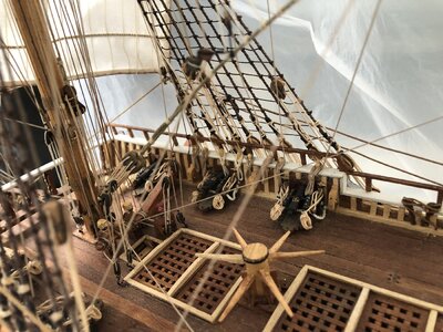
Below are a couple of pictures of the hanks along the railing. Various colours and rope sizes are required for the hanks to match the rope belayed at the various tying off points - not all running rigging is the same size or colour!!

Img_9529.jpg

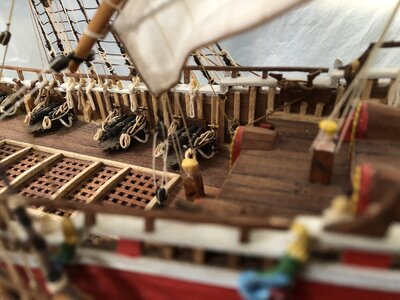
And looking under the mizzen sail to the midships belaying line-up:

Img_9533.jpg

One of the issues that arose while I was placing these rope hangings was that many of the belaying pins lie directly above a cannon. I am not sure how this would have been handled on a real ship. It is most likely that the belaying pin would have been moved aft or forward, away from the cannon barrel, but of course, I didn't think of that at the time I was putting them in!! A word of caution to future Vasa builders - Move the belaying pin locations so they do not occur above a gun barrel. I have had to live with the hank of rope lying to one side of the barrel or other, and it doesn't look as I would have liked it to be, but cannot change it now!!

Regards,

PeterG
 
Last edited:
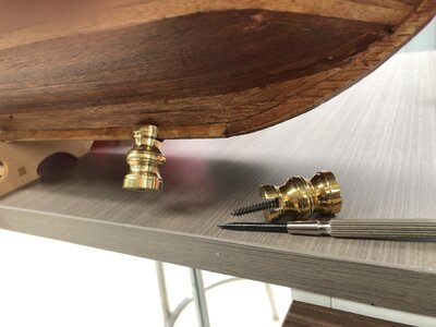
In post #395 I described the baseboard that I will use to mount the ship, forming the base of a display case. I haven't yet spoken about how the ship will be mounted to the baseboard. I have had made three small brass 'stands' which are flat at the base, but with a threaded hole to screw a bolt and on the upper end, a 5 mm slot for the keel to slip into, with a securing screw that is accessed through the thread hole at the bottom.

The picture below shows how these 'stands' are attached to the underside and keel of the ship.

IMG_9059.JPG

Once screwed into place, the stands are very tight and I think I will be able to have the ship vertical and mounted securely with these three stands secured to the base board. Positioning of the stands required that I mount all three into the keel, placing it along a centreline of the baseboard, and then drilling three holes at their correct locations to accept the bolts into the bottoms of the stands. Once positioned and marked, I then removed the brass stands from the ship to continue with the build. It was just too dangerous to leave the stands in place while continuing the finishing stages of the ship, and so she returned to the safety of her cradle mount until finished.

Regards,

PeterG
 
This is the voice of experience speaking on your part, Peter. It is so true what you say about the belaying pins. When placing them, who would have thought that they may interfere with the cannon barrels, but it's only once both are installed, that you will be able to see how it pans out. Great tip for VASA builders who have yet to complete this stage of the build. I can assure you though that the few which hang to a side of a cannon barrel, do not detract from your magnificent build at all.
 
Many thanks for your kind words Heinrich.

Hindsight is a wonderful thing, but if other builders are forewarned, then it will be my gift to them.

There have been so many great modellers on this forum, that we can all learn from other’s experience, ideas, and mistakes. It definitely pays significant dividends by reading and researching widely, but when you come across those ‘gems’, where you say to yourself “I must remember that…”, then it is best to capture it by writing a reminder or reference to the information for a later date. This hobby is so full of these ideas, innovations and original thinking, it makes a great example of how we should all live our lives more generally.

Thanks Heinrich,

Regards,

PeterG
I really enjoy your postings, Peter. It speaks of sensitivity and wisdom encompassed in a beautiful build.
 
With other demands on my life, the Vasa and my Build Log have taken a back seat for a little while but I hope soon to get back to her with a bit more time (and warmer weather available - remember, we are Down Under so it is our winter and my build dockyard is in an outside shed with minimal heating!!).

I am aware from my previous post (#395), I listed a few of the jobs yet to be done. The first thing I listed was the rope hanks along each belaying point.

I have been making rope hanks when I can and hanging them off the belaying pins along the rail. I only have a few more to do, but it's not until you make a few of these that you realise just how many ropes and hanks are needed to every belaying pin accounted for.

Below are a couple of pictures of the hanks along the railing. Various colours and rope sizes are required for the hanks to match the rope belayed at the various tying off points - not all running rigging is the same size or colour!!

View attachment 321488

And looking under the mizzen sail to the midships belaying line-up:

View attachment 321489

One of the issues that arose while I was placing these rope hangings was that many of the belaying pins lie directly above a cannon. I am not sure how this would have been handled on a real ship. It is most likely that the belaying pin would have been moved aft or forward, away from the cannon barrel, but of course, I didn't think of that at the time I was putting them in!! A word of caution to future Vasa builders - Move the belaying pin locations so they do not occur above a gun barrel. I have had to live with the hank of rope lying to one side of the barrel or other, and it doesn't look as I would have liked it to be, but cannot change it now!!

Regards,

PeterG
Hi Peter, yes, I will have the same problem with the belaying pins. Lesson learned.
 
With other demands on my life, the Vasa and my Build Log have taken a back seat for a little while but I hope soon to get back to her with a bit more time (and warmer weather available - remember, we are Down Under so it is our winter and my build dockyard is in an outside shed with minimal heating!!).

I am aware from my previous post (#395), I listed a few of the jobs yet to be done. The first thing I listed was the rope hanks along each belaying point.

I have been making rope hanks when I can and hanging them off the belaying pins along the rail. I only have a few more to do, but it's not until you make a few of these that you realise just how many ropes and hanks are needed to every belaying pin accounted for.

Below are a couple of pictures of the hanks along the railing. Various colours and rope sizes are required for the hanks to match the rope belayed at the various tying off points - not all running rigging is the same size or colour!!

View attachment 321488

And looking under the mizzen sail to the midships belaying line-up:

View attachment 321489

One of the issues that arose while I was placing these rope hangings was that many of the belaying pins lie directly above a cannon. I am not sure how this would have been handled on a real ship. It is most likely that the belaying pin would have been moved aft or forward, away from the cannon barrel, but of course, I didn't think of that at the time I was putting them in!! A word of caution to future Vasa builders - Move the belaying pin locations so they do not occur above a gun barrel. I have had to live with the hank of rope lying to one side of the barrel or other, and it doesn't look as I would have liked it to be, but cannot change it now!!

Regards,

PeterG
Well, me too...

And I just checked the 1:10 and Peter is correct - the belay pins never sit tight over the cannons...
 
Gentlefolk,

My humblest of apologies - My Build Log has again fallen into the cracks and it's been a while since I last posted an update.

I am at the stage of finishing off a few smaller details. For example, I have just added two 'svalbel'. These were 'brooms' made on board the ship for washing either, the anchors as they were lifted from the bottom, or cleaning the 'seats' of ease', positioned in the bow. Below is a picture of one of my 'svalbels'. The second is on the opposite side.

IMG_9800.JPG

I have made these out of some paintbrush hairs, trimmed and bound to a shaped piece of timber. Simple to do but quite a 'talking piece'.

Regards,

PeterG
 
Gentlefolk,

My humblest of apologies - My Build Log has again fallen into the cracks and it's been a while since I last posted an update.

I am at the stage of finishing off a few smaller details. For example, I have just added two 'svalbel'. These were 'brooms' made on board the ship for washing either, the anchors as they were lifted from the bottom, or cleaning the 'seats' of ease', positioned in the bow. Below is a picture of one of my 'svalbels'. The second is on the opposite side.

View attachment 341521

I have made these out of some paintbrush hairs, trimmed and bound to a shaped piece of timber. Simple to do but quite a 'talking piece'.

Regards,

PeterG
Nice detail!
 
Way back in post #395, I listed a number of things I still had to do to complete the ship. In this list below I have labelled the DONE items:

- Finish the various rope hanks for the running rigging lines onto the belaying pins - Still a lot to do!! - DONE
- Construct and add the stern lantern (a significant project in itself) - DONE
- Add rudder safety line/ropes - DONE
- Add flagstaffs and then make the flags and add these (a lot of research on the best way to do this...) - DONE
- Touch-up some sculptures and add additional final detailing and painting - DONE
- Add the roundels on the tops of the galleries. These are painted and ready but need fitting - DONE
- Add mast top section round things (at the very top of the masts), like hats (what are they called?) - DONE
- Final examination, fiddly bits I have forgotten after checking instructions etc etc. - DONE
- Mount ship to base board and ensure perspex cover fits OK plus finish wiring etc. - DONE

In addition to the above I added some svalbels and gave the ship a last clean. It is amazing how much 'build litter' sawdust and just 'stuff' falls on the ship/rigging etc. I have used a combination of small paintbrushes, can of compressed air, and a small tube extension I made for my portable vacuum cleaner. These worked well and I didn't damage any parts, so was pleased with that.

Rather than post pictures of the individual items above, I have made a 'poor man's movie', which I post below. This was done with an iPhone and a very old, unsteady hand so please forgive some of the shakes. You may have to zoom in the view on your display to get a better sized video OR hit the little 'fill-screen' button at the bottom right of the video display..

View attachment Vasa_Finished_HiRes_Conv_x264.mp4

The ONLY remaining thing to be done is to position the ship on its baseboard in the house, and then place the perspex enclosure over the top. That then will be the completion of this build.

Oh - While I think of it. In the video, you will notice there is an electrical plug-in connection attached to the baseboard. This gets connected to an external low voltage transformer and operates the internal lighting LEDs of the interior of the ship. I'll try and get a nighttime picture and post that.

Regards,

PeterG
 
Last edited:
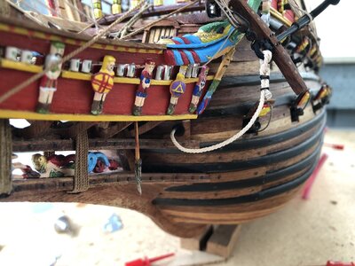
For a little more detail of the flags and the aft lantern, see the picture below:

Lantern_Flag.jpg

The lantern I bought from a shop and have 'made' it fit by adding brass wire supports and shortened its height. It seems to be in scale reasonably well and suits the stern fittings and era. I have also drawn a bit on Landstrom's book and his examples of the lanterns and how they were fitted.

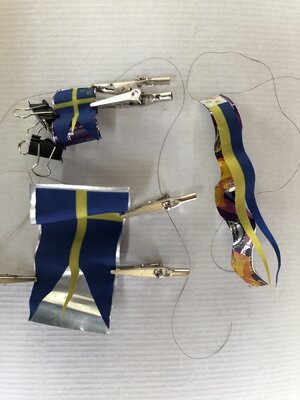
The flags were a complete exercise of their own. I was impressed by the method of laying the double-side printed fabric laid down onto folded aluminium can and used this technique to shape the flags. The picture below shows the shaped aluminium from a can, and then the flags pressed onto them and held with crocodile clips. Once in place, I painted the flags with 50:50 diluted PVA glue and when dry, removed the flags from the aluminium shapes so they held their shape.

IMG_9673.JPG

Note in the flag sides which go against their poles, I have inserted some thin pendant rope and folded the flag material over and glued it in place. This then gave me a halyard for hoisting the flags to their flagpoles.

I have only used three flags (aft, mainmast, and sprit mast). This seemed enough, and I had to take care that the flag and wind directions were all consistent, in my case from the aft port quarter.

Regards,

PeterG
 
Dear Peter. Words cannot describe what you have achieved here. I maintain that if there had to be a "Team Championship" on SOS, I cannot imagine any other ship model coming close to the VASAS built by you, @dockattner Paul and @Daniel20 Daniel. And while the kit manufacturer may be different and the three of you may have chosen to accentuate different priorities, the outcomes are universally spectacular.

You have achieved a level of authenticity with this build that will be very hard to emulate for anyone with any build. I can only admire and stand in awe.
 
Heinrich,

Your words are too complimentary. Many thanks.

I set out on this build to honour the ship that I saw and was so impressed with after visiting the Vasamuseet in Stockholm. For all those who have visited this ship, you too would appreciate what Paul, Daniel and I (the WASA TEAM) were intending to achieve.

Many thanks I extend to many people - They include all those who have commented and contributed on this SOS forum (that includes you Heinrich) but also Dr Fred Hocker and a large number of other Vasa (and other) ship modellers who have gone before, and provided such wonderful examples, reference material and knowledge of the ship, build techniques and the builds they have achieved.

Of special mention and credit must also go to the researchers, workers and restorers of the Vasa and all those who I have communicated with outside the SOS forum - such support and dedication to the restoration, love and history of this remarkable ship is unsurpassed.

Although I will move on to a new modelling venture, the Vasa will hold a special place in my and my family’s heart (not to mention a special place in our lounge room).

Again, many thanks Heinrich,

Regards,

PeterG
 
Well Peter you certainly have an absolutely gorgeous Vasa there. I really can't thank you enough for all the help you have provided me with your build log. I'm going to have to try your method of flag animation, really striking. Your lamp is perfect, and the short video was excellent. Thank you, my friend. I count myself as fortunate to be in the company of all the amazing Vasa builders in this wonderful, fun, educational forum.
 
Back
Top