Vasa Build Log - Billing Boats - Scale 1/75 [COMPLETED BUILD]

Vfordyce - Yes but it’s all about your point of view I guess. To us, you Northern Hemisphere types a pretty upside down too. Ahh, the wonders of the internet.

At the moment we are not so much upside down as backward - Nearly the whole country is in Covid lockdown for a couple of weeks with the Delta variant threatening!! I am OK because I am in a rural area but the cities are doing it tough.

Dean - This forum thrives on constructive criticism, so, not nit picking, just pointing out a legitimate error (many thanks). A sharp eye…

PeterG
Our prayers are with you, Peter. It’s easing up here in Texas.
 
Many thanks for your caring comments guys. My family live on a rural farm and so we can naturally isolate away from others. For going to town etc we wear masks etc but the Boss (she who must be obeyed) and I are also vaccinated, at least with one jab. Second jab at the end of the month. I don’t think the dog, horses and cows count - ever tried putting a mask on a cow!!!

PeterG
 
Not only is your Vasa outstanding for all of the extra care and attention you have paid to the tiny details, and their execution - I really love how you incorporate so many pictures of the actual ship from angles I have never seen before. This is an excellent model. If I could make one criticism of the kit, though, I would say that the fore and main tops seem too small a diameter for practical purposes.
 
Many thanks for your complimentary words @Hubacs Historian (HH).

About your comments regarding the size of the tops - it is an interesting observation and one that I will investigate. I have some plans from the Vasa museum plus some pictures that I may be able to estimate tops diameters. I will let you know if my findings. The tops are as per the Billing’s supplied design but I’ll look at it.

PeterG
 
Well, I followed up on the diameters of the tops, Hubacs Historian, and it is quite interesting. The following table shows my measurements.

Tops_Sizes.jpg

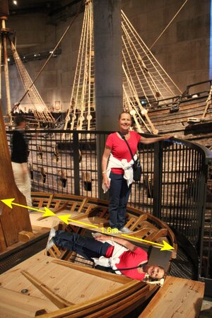
I have measured the Billing Boats plans, the actual model, plus the Vasamuseet published plans (of the 1990s). Much of the tops and upper mast sections were not preserved in the raising of the ship so there is some conjecture over the sizes of the tops. That said, there are lower tops on each of the masts, so were they in fact brought to the surface? If you allow for only the scales (museum plans are 1:100 scale and the model is 1:75), so the above would indicate that the Foremast top is slightly smaller (by about 2.3 mm than the museum plan drawing). In the case of the Main and Mizzen tops, the diameters of the model are slightly larger in diameter than estimated by the museum. I also include a column of the anticipated tops diameters (in metres), estimated from the Museum Plans. Interestingly, at the Museum, there is a detailed reconstruction of the Mainmast top (shown with 'She who must be obeyed' below):

Tops.jpg

I realise this is HIGHLY INACCURATE, but if you lie the Boss down (and she is 1.6m high), and then add, say 0.6m to the centre of the mast section, that gives a radius of 2.2m, so a diameter of about 4.4m which is not too far off the 4.2m scaled in the table above. As I say, highly inaccurate, but its in the ballpark.

Does this answer your question, HH? It would be worth asking Fred Hocker, given that the Mainmast top is reconstructed in the Museum, so where did they get its dimensions, or are they taken from the actual ship.

PeterG
 
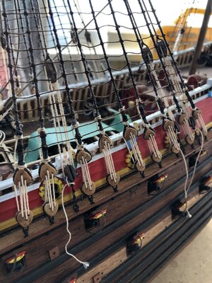
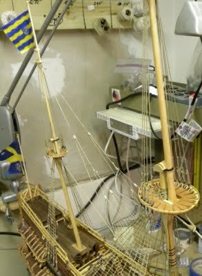
Following on with the build log, I have now secured all the lanyards of the standing rigging shroud deadeyes. Now back in Post #236, Dean62 highlighted an error in that I had rigged one of the mainmast deadeyes upside down. I have now corrected this and the photo below shows this done but also with the deadeye lanyards secured. This makes the appearance much neater and I have tried to keep it consistent with the actual ship photos of this part of the standing rigging.

IMG_8159.JPG

For each deadeye I have done two winds of the lanyard immediately above the deadeye shroud wrapping, and then extended it up two ratlines (about 32 inches in real length), and then a clove hitch to tie it off. Every shroud has been done the same way. You can see the lanyard extending up the shroud and tied off accordingly.

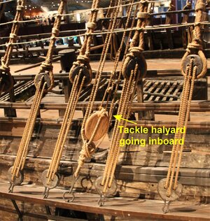
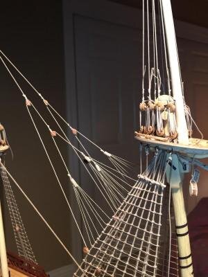
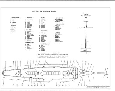
Now that the shroud lanyards have been secured, it does raise another question - For each of the tackles, you can see that their halyard lines are hanging loose. The question is, how were the ends of these secured? Being tackles, there would have been the need to adjust these for mast tension as the ship was sailing, so they must have been accessible inboard, and secured on a bollard or belaying pin. However, I can find no reference as to how these were secured or evidence in photos of bollards at the appropriate locations. The belaying pins are largely accounted for in the Fastening Diagrams which detail the belaying pins, but none relate to tackle halyards. Note too in the picture below that the shroud deadeye lanyards can be seen with their wrapping just above the deadeye.

Tackle_Halyard_1.jpg

On the photos of the rigging of the ship, the tackle halyards can be seen going through the top railing to go inboard, but I cannot see where they are attached. These would have been under considerable tension and so would have required a substantial tying off point. Anyone have any ideas?

PeterG
 
It ssemse the
Following on with the build log, I have now secured all the lanyards of the standing rigging shroud deadeyes. Now back in Post #236, Dean62 highlighted an error in that I had rigged one of the mainmast deadeyes upside down. I have now corrected this and the photo below shows this done but also with the deadeye lanyards secured. This makes the appearance much neater and I have tried to keep it consistent with the actual ship photos of this part of the standing rigging.

View attachment 242298

For each deadeye I have done two winds of the lanyard immediately above the deadeye shroud wrapping, and then extended it up two ratlines (about 32 inches in real length), and then a clove hitch to tie it off. Every shroud has been done the same way. You can see the lanyard extending up the shroud and tied off accordingly.

Now that the shroud lanyards have been secured, it does raise another question - For each of the tackles, you can see that their halyard lines are hanging loose. The question is, how were the ends of these secured? Being tackles, there would have been the need to adjust these for mast tension as the ship was sailing, so they must have been accessible inboard, and secured on a bollard or belaying pin. However, I can find no reference as to how these were secured or evidence in photos of bollards at the appropriate locations. The belaying pins are largely accounted for in the Fastening Diagrams which detail the belaying pins, but none relate to tackle halyards. Note too in the picture below that the shroud deadeye lanyards can be seen with their wrapping just above the deadeye.

View attachment 242299

On the photos of the rigging of the ship, the tackle halyards can be seen going through the top railing to go inboard, but I cannot see where they are attached. These would have been under considerable tension and so would have required a substantial tying off point. Anyone have any ideas?
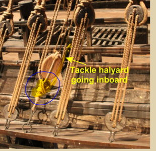
It seems the halyard is tied off below the block, which I circled, and then the excess rope thrown over the railing and possibly coiled on the ground?

1625595091124.png
 
Many thanks @Dean62. Your comments are valid, and I think in part you are correct, but my experience on sailing boats suggest that these tackles are used to adjust mast tension while sailing. Therefore, they would usually be able to be adjusted as the ship moves along. This requires the tackle lines to be adjusted as required and I would imagine, from inboard, so belaying to a bollard or belaying pin inside the deck area. I agree however that it appears as though the lanyard is tied off at the base of the pulley, which would preclude its adjustment from inside the ship. It's a bit of a quandry.

At this stage I have modelled by tying off as shown and then looping through the railing. I will have to decide whether I put some bollards to tie off inboard or simply roll and place on the deck as you suggest - Not sure yet.

PeterG
 
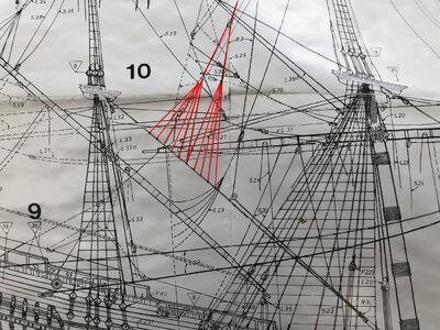
Moving onward with standing rigging (slowly), I have begun to fit some of the stays and backstays of the masts and in particular, the backstay of the Topmast of the Main mast. So, to begin, if we examine the Billing Boats rigging diagram (below), I have marked the Topmast backstay. It extends from the Topmast top to a single block, which then extends to two small blocks that have four lines that extend down and are secured to the Mizzen stay (as shown).

Img_8173.jpg

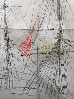
Now this is fine and if we look at the Vasamuseet rigging plans, the same is shown (see below), with the backstay extending down, two blocks and then eight support lines onto the Mizzen stay.

Img_8172.jpg

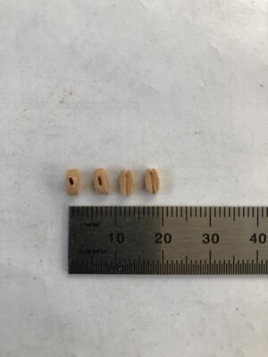
So far so good. The only complication I saw was that the small blocks that allow the 4 lines to go to the backstay were not in the kit. These are oval shaped and with a broader running slot than a single block. My alternative was to make these, so I did with my trusty supply of Tasmanian Huon Pine (which I have described in a previous post). I show these blocks below and they did the trick nicely (after a bit of painting/dyeing).

IMG_8171.JPG

IMG_8165.JPG

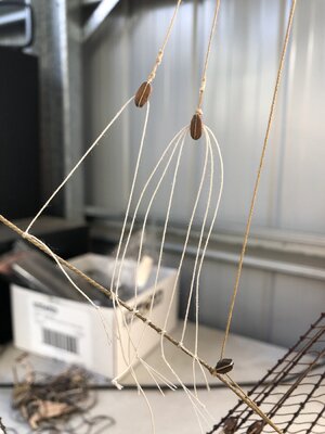
Above is a picture while I am rigging these lines. Note that getting the tension right is a nightmare, but after a lot of loosening and tensioning, its pretty good. I have used white rope which I have also used for lanyards (of for example the shrouds), but I don't think I am a fan of it in standing rigging, so I will probably change to a darker, maybe brown rope.

Now, the NEXT problem. If you examine the Billing plans and the Vasamuseet plans above, you will notice that there are two additional stays coming from the Mizzen Topmast which extend through a similar block arrangement and are tied off on the back of the Mainmast aft shroud. This apparently was common practice in the early 1600's and is consistent as per R.C. Anderson's book. If you examine the rigging arrangement however you will notice there is the Mizzen Topmast stay which comes down from the Topmast top, to a single block. From this block, four lines would have to radiate out, two to port and two to starboard for the third block to secure the lines to the back shrouds of the Mainmast rigging. While this appears OK, what I found was that the Main Topmast backstay (as already described), is in the way. They both run down the centreline of the ship and so would be touching and fouling each other.

So, what is the solution? Well interestingly, on Clayton's Vasa 1/50th model build, he has aligned the Mizzen Topmast stay, in fact as TWO stays, and this approach, neatly lies on either side of the Main Topmast backstay and is clear without touching. The picture below shows Clayton's rigging where you can see the Mizzen Topmast stays coming forward to be secured to the Mainmast back shrouds.

Clayton_MainTopmastShrouds2.JPG
(Clayton's rigging showing the two stays coming forward from the Mizzen topmast top).

So, this solution is how I will do my Main topmast backstay and Mizzen topmast stays. This has been an interesting exercise with some research having provided a solution.

Elapsed Time 2165 hrs.

Regards,

PeterG
 
Moving onward with standing rigging (slowly), I have begun to fit some of the stays and backstays of the masts and in particular, the backstay of the Topmast of the Main mast. So, to begin, if we examine the Billing Boats rigging diagram (below), I have marked the Topmast backstay. It extends from the Topmast top to a single block, which then extends to two small blocks that have four lines that extend down and are secured to the Mizzen stay (as shown).

View attachment 244402

Now this is fine and if we look at the Vasamuseet rigging plans, the same is shown (see below), with the backstay extending down, two blocks and then eight support lines onto the Mizzen stay.

View attachment 244408

So far so good. The only complication I saw was that the small blocks that allow the 4 lines to go to the backstay were not in the kit. These are oval shaped and with a broader running slot than a single block. My alternative was to make these, so I did with my trusty supply of Tasmanian Huon Pine (which I have described in a previous post). I show these blocks below and they did the trick nicely (after a bit of painting/dyeing).

View attachment 244406

View attachment 244407

Above is a picture while I am rigging these lines. Note that getting the tension right is a nightmare, but after a lot of loosening and tensioning, its pretty good. I have used white rope which I have also used for lanyards (of for example the shrouds), but I don't think I am a fan of it in standing rigging, so I will probably change to a darker, maybe brown rope.

Now, the NEXT problem. If you examine the Billing plans and the Vasamuseet plans above, you will notice that there are two additional stays coming from the Mizzen Topmast which extend through a similar block arrangement and are tied off on the back of the Mainmast aft shroud. This apparently was common practice in the early 1600's and is consistent as per R.C. Anderson's book. If you examine the rigging arrangement however you will notice there is the Mizzen Topmast stay which comes down from the Topmast top, to a single block. From this block, four lines would have to radiate out, two to port and two to starboard for the third block to secure the lines to the back shrouds of the Mainmast rigging. While this appears OK, what I found was that the Main Topmast backstay (as already described), is in the way. They both run down the centreline of the ship and so would be touching and fouling each other.

So, what is the solution? Well interestingly, on Clayton's Vasa 1/50th model build, he has aligned the Mizzen Topmast stay, in fact as TWO stays, and this approach, neatly lies on either side of the Main Topmast backstay and is clear without touching. The picture below shows Clayton's rigging where you can see the Mizzen Topmast stays coming forward to be secured to the Mainmast back shrouds.

View attachment 244409
(Clayton's rigging showing the two stays coming forward from the Mizzen topmast top).

So, this solution is how I will do my Main topmast backstay and Mizzen topmast stays. This has been an interesting exercise with some research having provided a solution.

Elapsed Time 2165 hrs.

Regards,

PeterG
Oh boy! Once I get to this point I will rely heavily once again on your build. I like the way you isolate the rigging on the plans with color coding.

Daniel
 
Fantastic Peter. Thank you for your careful description! I have a question/observation. On Clayton's model it appears that there is an additional block on the mizzen topmast stay(s) midway between the mizzen top and the first split into two lines (subsequently into four lines). I do not see the tensioning line on the plans you show for the mizzen stay but that configuration does appear on the main topmast backstay. Or am I seeing things? I have never tried to interpret rigging diagrams. This is going to be a nightmare for me. Keep the posts coming!
 
Fantastic Peter. Thank you for your careful description! I have a question/observation. On Clayton's model it appears that there is an additional block on the mizzen topmast stay(s) midway between the mizzen top and the first split into two lines (subsequently into four lines). I do not see the tensioning line on the plans you show for the mizzen stay but that configuration does appear on the main topmast backstay. Or am I seeing things? I have never tried to interpret rigging diagrams. This is going to be a nightmare for me. Keep the posts coming!
Paul, could you repeat that one more time?o_O
 
One thing I have been keen to pursue as to insights of the standing rigging, of course, would be the availability of the Vasa II book by Fred Hocker. As we all know, this has taken an age to publish and be made accessible. In my searches however I came across this post on the British model space forum site.

The following is from an email directly from Fred and is dated November 2020. For those who have not seen it, I reproduce below:

“Vasa II, covering all of the rigging finds, the reconstruction of the rigging, and evaluation of how a ship like Vasa might be sailed, is currently in the layout process, but this has been delayed by the Covid pandemic. As it now stands, Vasa II will appear in two parts, in order to make it manageable (the total work is over 500 pages long with over 500 illustrations). The first part, covering the presentation of the archaeological remains in eleven chapters, should appear next year if the production process can recover from the disruption caused by the pandemic. The second part, which will be more integrated discussions of the rigging and sailing process, will then go through a faster layout and printing process, since the design and formatting work will already have been done. Part 1 will be physically larger, but part 2 will be accompanied by large scale (we are hoping 1:50) drawings of the reconstructed rig. The books will be available from the museum directly, but it will be easier to order them from the publisher (Nordic Academic Press) and their international distributors. Once we have a firm date for the book launch, I will provide the relevant information to this forum and others.

The eleven chapters in Part 1 are:

1. Introduction
2. Rigging elements fastened to the hull (chainwales, bitts and knights, catheads, fixed blocks and fairleads)
3. Spars (masts, yards and fittings fastened to them, such as sling cleats)
4. Tops
5. Tackles (deadeyes, euphroes, blocks, parrels, fairleads)
6. Cordage
7. Sails
8. Capstans and windlass
9. Anchors (including anchor buoys)
10. Steering
11. Navigation (compasses, bittacle, timekeeping, sounding leads)

Part 2 will cover:
12. Reconstruction of the rig as a whole
13. Sailing environment and performance
14. Economics and logistics of supplying the sails and rigging
15. The process of rigging the ship
16. Sailing the ship
17. Experience of sailing a modern reconstruction of this rig (Kalmar Nyckel)
18. Conclusions

Cheers,
Fred Hocker

Just to keep you up to date if you haven’t seen this email.

PeterG
 
Paul (Dockattner), thanks for your question. I am a little unsure of your specific inquiry. To assist I note that in another build log (https://modelshipworld.com/topic/7900-vasa-by-mar3kl-billing-boats-scale-175/page/7/) Mark has also used two mizzenmast top mast stays but then rigged a block below the four lines to the mainmast aft shroud. The line then goes down to a belaying pin on deck.

1626482655069.jpeg

Does this answer your question Paul? If not could you maybe indicate the block concerned on the Clayton picture?

Regards,

PeterG
 
On re-examining and rereading your post Paul, I think you are correct. There do not appear to be three sets of blocks on the top mast stays with only two indicated in the Vasamuseet rigging plan. Clayton and Mark however seem to have used three sets of blocks similarly to the main top mast backstay.

So, to clarify, from EACH top mast stay (and there are two), the first single block has a tensioning line going to a block on the aft shroud, and then to deck. The second block is also a single block which divides two lines going to two euphroe blocks that takes the crows feet lines to the main mast aft shroud.

1626498713895.jpeg
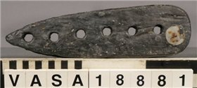
Vasa euphroe block.

Note that euphroe blocks on Vasa came in three sizes with from four to six holes for dividing lines. I reference this from Fred Hocker on the warship vasa forum. There is no specific evidence mentioned but Fred says they could have been used for crows feet or for the martnets on the fore and main courses.

Interestingly too, you will note that in the original picture from Clayton, he has not rigged a main topmast backstay with crows feet attached to the mizzenmast stay. In a post, again in the warship vasa forum, Fred Hocker posts that he was incorrect in his original advice to Clayton in advising there were unlikely to be top mast backstays. He says:

“There is no clear evidence either way, but I think that on balance there were probably topmast backstays on the fore and main. This is different from what I told Clayton when he was rigging his model, but we had not documented the chainwales at that point. The chainplate fixing points on the fore and main suggest one backstay to the topmast head, probably rigged from the next-to-last chainplate position and probably rigged as running backstays. Backstays are attested in English sources from the beginning of the 17th century (they appear in the survey of fleet rigging carried out in 1611, for example) and show up in images of ships at about the same time. Baltic practice may have been a little behind developments in the more demanding North Sea/Atlantic basin, and the detailed inventory of the rigging for Tre Kronor in 1626 is not definitive, but I think that they were in use on large ships by the 1620s.

Clayton, it should be possible for you to rerig your model...

Fred“

and Clayton replies with:

“It would probably be possible to do some modifications. The next time I will have it out of the case will be October when we have our annual model club show. I could probably do it then, and by then there could be drawings and more information.

Perhaps I could incorporate some other things too, such as the cleat or kevel instead of the pinrail attached to the inboard faces of the top timbers.

Clayton”
 
Thanks Peter. You have deciphered my cryptic question perfectly. That makes the most sense otherwise how could the mizzen topmast stay be tensioned?

While I am a long way from doing any rigging I have started to read and study so I can learn the language and the theory as best I can. Right now I can't see the trees because the forest is in the way - but when opportunities present themselves I am getting in the water with all of you Olympic caliber swimmers in an attempt to learn. I appreciate your thoughtful reply and willingness to address my question.

BTW: I had read Fred's quote previously and the whole thing makes me chuckle. People have been posting in their build logs for the past 7 or 8 years their hope that Vasa II will be out in time for them to work on their rigging. I am now in that same position. Maybe I'll be the lucky one? What a waste if that were true since so many more qualified builders will greet the publication with frustration: why couldn't this have been out when I was working on that ship!?!?!

I have learned that Fred is very kind and willing to answer questions via email - and he even sent me some drawings for the ship's boat on display at the museum. He is an amazing resource and generous with his time.
 
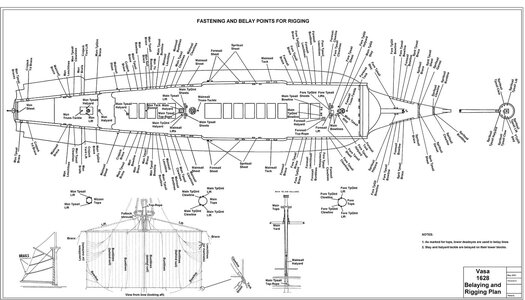
Recently there was a post by Paul (Dockattner) relating to the belaying points on the Vasa for running rigging. I am nearly up to this stage, and so have undertaken a fair bit of research to detail the rigging points on the ship. From my research there are three sources of plans which detail the Vasa Belaying Plan. I have two Belaying and Rigging Points plans available (in English) with a third derived from the other two in German, but its origins are basically the same (and my German is not good to interpret some of the points). Note that I am here referring to published rigging plans of the Vasa, and not those from the ship kits (Billing, D'Agostini or Artesania Latina). I have not seen the plans from Corel or other manufacturers.

Please note too, that each of the Belaying (Running Rigging) Plans is 100% speculation for the Vasa, even if we actually KNOW about her hull and deck layout! NO original plans survived (it can be assumed that they never existed), and not even a contemporary artists´ picture could tell much detail about her rigging!

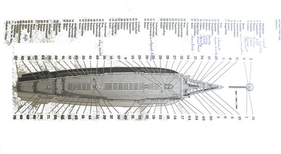
One plan is derived from the numbered index Plan drawn in 1970 (originally) by Vasamuseet and then updated later (about 1979/81) according to Fred Hocker. The second rigging plan is by the German, Stolt in 2009 derived from experience on the Gothenburg III replica (refer http://www.jans-sajt.se/contents/Navigation/Modelling/R_Wasa.htm). These three are shown below:

VASA MUSEUM PUBLISHED PLAN

Rigging+Deck_Secure_Points_English.jpg

STOLT 2009 RIGGING PLAN

Rigging+Deck_Points_1.jpg

GERMAN BELAYING PLAN DERIVED FROM THE TWO ABOVE

Rigging+Deck_Secure_Points.jpg

RESOLVING THE PLANS

My problem is that I have a few inconsistencies between the two plans. For ease of understanding of the ship's layout, I have edited the 1970 plans with labels and English titling at each belay point. While doing this, I have come across the inconsistencies which I believe I have largely resolved. There are some points which are still not final, but certainly the majority are consistent. Note too that there are a range of belay points to make lines secure. These include:

- Belaying pins of the conventional sense which may occur in a pin rack, or along the railings of the topside deck of the Vasa
- Kevels which lie along the deck railings (port and starboard and on the front fore-railing) are larger and capable of securing larger, high tension lines
- On deck eye bolts which may have line loops or line hooks that allow the line to run to a position as required
- Cleats (such as on the base of the mizzen mast) and on the bowsprit.
- In-hull secure points for halliards with pulley belay points to allow very strong haul points. These points may be below deck to allow the line to exit through a companionway.
- Knights heads of which there are a number on the deck of the Vasa
- Belay rack timbers (also called bitts) which extend between two support posts and allow lines to be secured. Not that on the Vasa these were NOT holed for belay pins but are solid timber lengths.
- Other belay points such as deadeyes or stays and fixed rigging on upper masts.

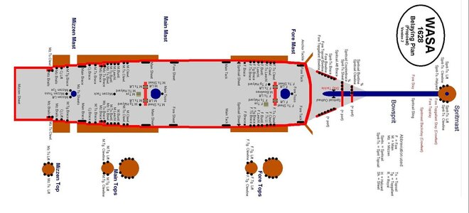
So, the outcome of my editing is provided below. In this diagram, I have interpreted the number index of the museum's plans and inserted the English term for the rope belay points. Also note that I have added some diagrams to help address some of the rigging terms specifically used for sail control (eg clewlines, buntlines, tacks etc).

Rigging+Deck_Secure_Annotated_Points.jpg

To assist people who may want to use this diagram, I also include a PDF below which allows printing at your desired scale. If there are comments about this diagram, please feel free to add them to improve the plan. It is definately a work in progress.

PeterG
 

Attachments

  • Rigging+Deck_Secure_Annotated_Points.pdf
    584.2 KB · Views: 30
Last edited:
Simply WOW Peter!

Two things:

1. Can you clarify the belay details for the aft points labeled Crojack Yard Brace and Mizzen Topsail Brace. Were the ropes tied directly to the cap-rail (or maybe to the 'spindle' for the rail)? Or were they belayed in some other way?

2. I'm sure you've seen this but Fred H. says that there were no pinrails along the bulwarks (https://warshipvasa.freeforums.net/thread/56/pinrails). So, what is your plan? Just add them to the cap-rail?

Thank you SO MUCH for sharing your research. You just saved me a massive job (now I only have to learn what all these rope names refer to!!!!).
 
Back
Top