Vasa Build Log - Billing Boats - Scale 1/75 [COMPLETED BUILD]

I apologise for the time between Log Build entries - Unfortunately I have been distracted for a protracted period while I actually earn some money. I am retired, but occasionally a client from old times contacts me and wants some work done. In the process they are actually willing to pay money, so, in the eyes of the Boss, this takes higher priority. In the background however, I have been trying to do a bit on the Build.

Sails are taking a LOT longer than I thought they would. Unfortunately, they pose a lot of questions too for which I am having difficulties in getting answers through research or other builds. So, where am I up to? - Well I have the sails (only five of them) all sewn, and I have applied the boltropes around the outside (see previous entries). The next task is to attach the sails to the yards.

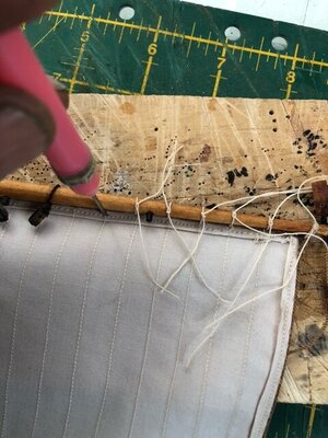
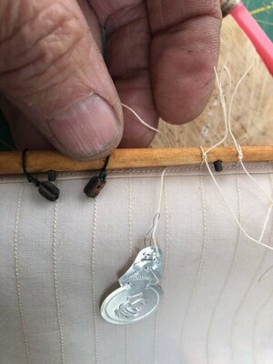
Despite the instructions from Billings (which uses a running knot and loop type of attachment), I have opted to attach the sails by creating ‘robands’ (the correct term I think), by threading some thin white line through the top of the sail and for each seam in the sail, I wrap it around the yard and then loop it over itself and then back to the aft side of the sail. This leaves one end of the line aft and one forward. I have then done a reef knot tightly over the yard with the two ends. In each case, where the line goes through the sail, I pierce the sail fabric through the triple hem and then use a needle threader to allow the line to pass through (see below).
7.jpg

6.jpg

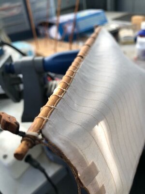
Each wrap around the yard has the reef knot as seen above, but when completed, it makes a neat and even length of rope wrappings and good solid attachment to the yard. I have used the attachment method as shown in Post #274 with each roband independently secured and a small drop of HP Cement to secure it before removing any excess line.
8.jpg

I have done this to all five sails and now am moving on to the running rigging of the sails/yards.

Regards

PeterG
 
Last edited:
Good to hear from you again Peter. As always your work is impeccable. I do resonate with your comment about not being able to find information at times. As privileged as we are to have the museum ship and the 1:10 - things like rigging details are in short supply. Throw in my total lack of experience and I'm feeling more than a little intimidated. As time allows I hope you will continue to show us your beautiful work!
 
Hello Peter,
I too occasionally receive a project from my former employer and I own a small cartography company which combined with model ship building keeps me well occupied during my retirement (and out of the admirals way).

Your sails look great, I really like the clean crisp even spacing of the attachment ropes. I have a ways to go before considering sails though.
 
I apologise for the time between Log Build entries - Unfortunately I have been distracted for a protracted period while I actually earn some money. I am retired, but occasionally a client from old times contacts me and wants some work done. In the process they are actually willing to pay money, so, in the eyes of the Boss, this takes higher priority. In the background however, I have been trying to do a bit on the Build.

Sails are taking a LOT longer than I thought they would. Unfortunately, they pose a lot of questions too for which I am having difficulties in getting answers through research or other builds. So, where am I up to - Well I have the sails (only five of them) all sewn, and I have applied the boltropes around the outside (see previous entries). The next task is to attach the sails to the yards.

Despite the instructions from Billings (which uses a running knot and loop type of attachment), I have opted to attach the sails by threading some thin white line through the top of the sail and for each seam in the sail, I wrap it around the yard and do a reef knot tightly to the yard. In each case, where the line goes through the sail, I pierce the sail fabric through the triple hem and then use a needle threader to allow the line to pass through (see below).

View attachment 267701

View attachment 267702

Each wrap around the yard has the reef knot as seen above, but when completed, it makes a neat and even length of rope wrappings and good solid attachment to the yard. I have used the attachment method as shown in Post #274 with each roband independently secured and a small drop of HP Cement to secure it before removing any excess line.

View attachment 267703

I have done this to all five sails and now am moving on to the running rigging of the sails/yards.

Regards

PeterG
It looks like the running robands I have done, only neater.
 
Hi Daniel,

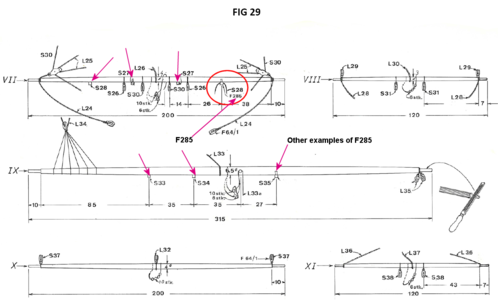
Regarding the brass fittings you have, I believe in the Billing Boats instructions, they are listed as F285, and there should be 37 of them. They are listed in the Manifest as being Eye Bolts. An obscure listing of their use I noticed in Fig 29 of the second part of the instructions which relates to the yard fitout. If you see in the diagram below, I have circled this fitting, however, in each case where they are used, there is also an indication of an Sxx number. This indicates one of the sail running rope lines which use the eye bolts along the length of many of the yards, especially the larger ones (eg mainsail yard, foresail yard etc). In some of the smaller yards (eg top gallants), the eye bolts are not required. When you get to this stage too, make sure you identify the Roman Numerals (eg VII, XI etc etc) with the Rigging Diagram, so you can then figure out the correct yard for the correct location on the ship. The Part 2 instructions too are at a scale of 1:1, so it does make it a simple matter of overlaying the dowels and shaped yards to get the dimensions correct.

1636425204074.png

For my Vasa, I have dipped each of these fittings in Brass Black to change their colour and then I have used them on the yards as indicated. In the rigging for each yard where appropriate, I have used them for buntlines mainly and that seems to fit with the labelling on the instructions. There are a lot of blocks attached to the yards as well as the eye bolts.

I have not used these anywhere else on the ship (eg deck or hull), as the kit also supplied some round, copper eye bolts which for deck securing of lines, seemed much more in scale and appropriate.

Regards,

PeterG
 
Last edited:
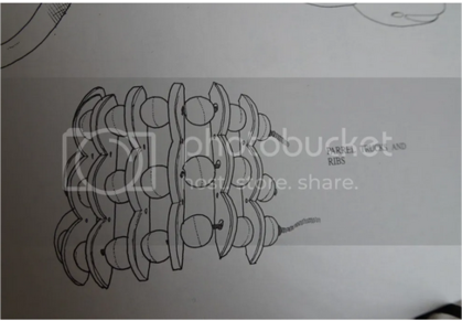
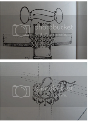
Moving on to the sails and yards, I have been thinking about how to attach the yards to the masts. The Vasa made use of parrels to achieve this and this is in keeping with the age of the ship and the accepted conventions/practice of the time (according to Anderson). A bit more research however, because, parrels by their design, are simple a grouping of vertical pieces of timber, between which are threaded some wooden 'balls' like beads and with rope that allowed the parrels to be tightened or loosened from deck when the yard was to be lowered or lifted along the shaft of the mast to raise and lower the sail. In fact, in Fig 29 of the Billing Boats instructions, you can see a hint of the parrels being used for the yards shown.

1636433697375.png
A parrel to be mounted around a mast to support a yard.

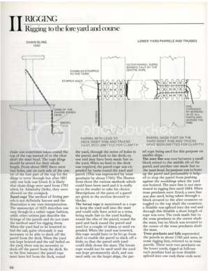
However, I like to question things to give a bit more detail - So, how big were the vertical timbers, how big were the beads (called 'trucks'), and how many were needed to surround the mast for various yards? The Billing kit provided a set of black, plastic beads ready to be threaded onto line with laser cut vertical plywood timber to construct the parrels. The mainsail and foresail yards have three groupings of trucks and the other yards (except the spritsails yards), have only two groups of trucks. Well, in my research, I came across reference to descriptions of parrels by Lees (the following information on page 168 of his Masting and Rigging English Ships of War 1625-1860 - albeit English ships but evidently suited to the Vasa given the timeframe:

"The lower yards had three rows of trucks and the others two rows. Except for the sprit topsail and topgallant yards, the length of the ribs on the lower parrels were one and a half times the diameter of the yard. For the sprit topsail and topgallant yards they were twice the diameter of the yard. The depth of the ribs was equal to the diameter of the trucks, and the width of the ribs was a quarter the diameter of the trucks. The trucks' diameter was one fifth the ribs length on parrels of three rows and one third the length of parrels of two rows. The length of the trucks was one and a quarter times their diameter."

1636433433700.png

OK, so using the above, the truck's diameter was 1/5 the rib length.
Rib length was 1.5 times the diameter of the yard.

For the Billing model, for the larger yards eg mainsail yard, it is about 10mm in diameter, therefore rib length was 1.5 x 10mm = 15mm and truck diameter is 1/5, therefore 1/5 x 15mm = 3mm truck diameter. The supplied Billing beads are 4.00mm - Close but no cigar!!. Now, this ship is at a scale of 1/75, therefore a 4mm bead equates to a truck of carved wood (usually ash, as far as I can gather), of 4mm x 75 = 300mm or 11.8 inches - That's a BIG ball to carve, but not impossible. For smaller yards (eg topsails and topgallants), the trucks would have been smaller.

Reading further into Lee's book:

Regarding British practice, Lees says: "The parrels for the yards comprised ribs and trucks, those on the lower yards made of of three rows of trucks, and the other parrels made up of two. The length of the ribs on the lower parrels were one and a half times the diameter of the yard, those on the mizzen yard, the topsail yards (except the sprit topsail and the spritsail yard were one and a half times the diameter of their yards; finally those on the sprit topsail, and all the topgallant yards, were twice the diameter. The depth of the ribs was equal to the diameter of the trucks and the width of the ribs was a quarter the diameter of the trucks. The trucks' diameter was one fifth the rib's length on parrels of three rows, and one third the length on parrels of two rows. The length of the trucks was one and a quarter times their diameter. A hole was bored through the trucks to take the parrel rope; holes were also bored through the ribs for the same purpose. The trucks were positioned so that 1/2 inch of truck protruded beyond the back of the rib. There was a slight cavity in the ribs in the way of the trucks."

So, for smaller yards, the parrels size is approximating 1/3 the rib length and the rib length was 1.5 times the yard diameter. So for a topsail yard (eg the fore topsail), the diameter for the Vasa model is about 4 mm, so 1.5 = 6mm rib length and truck diameter should be 1/3, therefore 2mm (or HALF the size of the beads supplied by Billing Boats). This to me was a problem. While I am happy to use the supplied beads for the larger yards, I went hunting for smaller beads to use on the upper yards.

Reading even further into Lees book, he describes the parrels and trucks of the Mary Rose. In this case a number of trucks were found in the wreck and on the seafloor and these were of varying size from about 70mm, up to 120mm (or only 2 3/4 inches to 4 3/4 inches). This to me seems a more reasonable and manageable size, but the Mary Rose was considerably smaller than the Vasa. I still have trouble getting my head around balls carved to 12 inches around!!

As far as the arrangement of lines and securing the trucks in the ribs around the mast and then around the yard, I have opted for a single, looped line which then returns to deck to allow adjustment of parrel tension for raising and lowering of the yard. A LOT of variation and not much certainty about how these were rigged seems to exist for many ships of this and later age, let alone the Vasa. Possible arrangements are shown below:

1636435269426.png

Regards,

PeterG
 
Looks great!

I recommend "The Rigging of Ships In The Days Of The Spiritsail Topmast, 1600-1720" by R.C. Anderson if don't already have it. Excellent resource, covers multiple countries rigging practice.

Peter
 
Thanks Peter.

Yes, I have used and relied on Anderson’s book on many occasions. It is a great reference. However, Anderson’s presentation on parrels is quite brief so I looked broader afield (ie Lee’s book).

Many thanks,

PeterG
 
Hi Daniel,

Regarding the brass fittings you have, I believe in the Billing Boats instructions, they are listed as F285, and there should be 37 of them. They are listed in the Manifest as being Eye Bolts. An obscure listing of their use I noticed in Fig 29 of the second part of the instructions which relates to the yard fitout. If you see in the diagram below, I have circled this fitting, however, in each case where they are used, there is also an indication of an Sxx number. This indicates one of the sail running rope lines which use the eye bolts along the length of many of the yards, especially the larger ones (eg mainsail yard, foresail yard etc). In some of the smaller yards (eg top gallants), the eye bolts are not required. When you get to this stage too, make sure you identify the Roman Numerals (eg VII, XI etc etc) with the Rigging Diagram, so you can then figure out the correct yard for the correct location on the ship. The Part 2 instructions too are at a scale of 1:1, so it does make it a simple matter of overlaying the dowels and shaped yards to get the dimensions correct.

View attachment 268552

For my Vasa, I have dipped each of these fittings in Brass Black to change their colour and then I have used them on the yards as indicated. In the rigging for each yard where appropriate, I have used them for buntlines mainly and that seems to fit with the labelling on the instructions. There are a lot of blocks attached to the yards as well as the eye bolts.

I have not used these anywhere else on the ship (eg deck or hull), as the kit also supplied some round, copper eye bolts which for deck securing of lines, seemed much more in scale and appropriate.

Regards,

PeterG
Hey thanks for the reply Peter. I do see F285 on the deck as well so there will be a shortage of 6ea. of them. No problem though I'll use something else.
 
Daniel,

I have used the supplied copper Eye Bolts (eye rings made of copper wire) for my deck fittings. I think these look more realistic and are easy to fit. In some cases I have had to add a number of additional eye bolts than are indicated in the instructions. You will probably find the same.

PeterG
 
Last edited:
Actual shape of the Vasa parrel ribs can be found here:

Interesting note that they are not flat but wedge shaped. Side facing mast, about 6 cm. Outer edge, about 8 cm
 
Last edited:
Thank you Peter (PJennsen). I am assuming you have some Swedish heritage, Peter, but this is a fantastic find. I was not aware of this resource or that examples of the parrel ribs had been recovered. It seems that the shape of the ribs which I am using is fairly close, but having three rope and trucks suggest these rib samples were from the larger yards.

The database metadata for the rib length (height) indicates 920mm and the Lees’ information suggests that trucks were between 1/3 and 1/5 the rib length times times 1.5.

Therefore with 920 x 1.5 = 1380mm and the truck diameter is then about 1/3 x 1380 = 460mm. This converts to about 18.1 inches for the larger yards (mainsail and foresail yards). In a subsequent post #299 PJannsen has listed a smaller parrel rib with height of 645mm. For this, rib length times 1.5 = 968mm and the truck diameter is 1/5 of this or 193mm (7.68 inches) for the smaller yards.

At scale this converts to beads for the larger yards of about 6.1mm and 2.57mm for the smaller yards. I can accommodate the lesser dimension (as the supplied kit beads are 4mm) but the larger beads I will have to obtain.

Overall, this is a great result. I was very dubious of the originally calculated 12 inch truck diameter but this recalculation, based on an actual parrel rib size, seems the Partell trucks were quite large and the kit supplied beads a reasonable compromise, at least for the smaller yards .

Can you imagine carving a dozen balls 18 inches in size!!!

It’s always so much easier when you are working from a ‘known’, rather than speculation!! Again, many thanks Peter,

Regards

PeterG
 
Last edited:
With considerable time and much painting, I have completed both the starboard and port side galleries and their artwork. The painting has taken the majority of the time but the shaping had to be carefully done so as not to melt or destroy the plastic figures. In the end, only a couple of retrievable disasters. The port quarter of the ship and the gallery artwork is shown in the picture below:

View attachment 115544

Some of the finer detail on some of the figures will need adjustment a little later as I am not happy with some of the beards on the faces in particular, and the eyes in some figures too, are a little large. Its really hard to make the irises in the eyes small enough but also to line up with the left and right eye positions. Some of the figures look decidely drunk or cross-eyed. I will have a go at repairing this when my hands feel steadier!!

So I now move to the artwork on the stern. The figures here are a mixture of large ornamentation pieces with quite complex detail (but on one piece of plastic base), as well as individual figures having guards/soldiers, musicians and gargoyle-like heads etc. In addition, on both the starboard and port rear corners of the stern are tall structures that extend above the topsides and require gradual and diligent painting as there are a number of kings and carvings like a totem pole. An off-centre photo of the stern is shown below:

View attachment 115545

For the soldiers guarding the rear Captain's Cabin windows, I have added long 'poles/staves' which are painted silver. On the real ship, these guards have their hands in a position where it is probable that they were holding weapons on the real ship, but they are not there now (see below for these on the museum Vasa).

View attachment 115546

A few other points of comparative interest:

- In the Billings Boats kit, I could not find the seven 'heads' of what look like chicken heads below the row of musicians. I 'scratched' these with some plastic frame material and then painted them to give the appearance as indicated in the 1/10 Vasa model and other Build Log descriptions.

- Above the corner guards on both the starboard and port edges of the original ship, are sculptures that are also not included in the kit. It appears to be Hercules and I might have to have a go at carving two of these guys to complete the corners of the stern. It would change the appearance considerably, rather than just having a stark corner join of timber.

- The row of 'angels' at the base of the stern sculptures had to have their heights reduced to allow them to fit correctly. Above their heads is a round 'halo' and at their feet is some 'ground' on which they stand. I decided to trim the 'ground' rather than cut off their halos, although the circular halos look a bit odd as they are relatively thick compared to the heads of the angels themselves. These 'angels' are also a bit risque in their state of dress (or undress) as the 'toga'-like garments they are wearing appear to be very much 'off the shoulder'.

Another picture of the stern, taken with a bit more light outside, shows the angels in their state of undress, and as I look at them a bit more critically, they actually look a little devilish, rather than angelic!!

View attachment 115548

In this photo too, I have added the stern rope portholes and the upper gun port figures. It's interesting what you pick up, even in writing this Build Log. I notice from the original ship photo that at the base of the upper, corner 'totem poles', there are bulbous, rounded knobs present that are not on the model. I will have to add these - Never noticed them before!!

This artwork when I think back to the effort it has taken, has probably been one of the more rewarding parts of this build. It takes a lot of time, but every addition adds a lot to the ship and makes her appearance more complete. I can only imagine how this ship must have impressed and awed those who built her and those who viewed her before her demise.

Time Elapsed: 1010 hours

Best regards,

Peter G.
That is a lot of paint work well done. I must remember not to get this ship as I don’t have those painting skills. How the ship stayed upright I have no idea....seems so tall vs the waterline.
 
Thanks Grant. You are correct about the painting of the structures and all the figures - It took a long time and I am still not happy with some of the detail. Other builders (eg DocAttner), have far exceeded my painting abilities.

However, you don’t have to approach it like this. Many modellers have used a single colour for all their sculptures (eg see Daniel’s (Daniel20) beautiful model, and others eg fmodjar ), where gold or even gold leaf has been used.

As you say, the Vasa sank primarily due to a top-heavy design with insufficient below waterline hull support. Some of the cross-section diagrams really show this with a very small below waterline section compared with what lay above the lower gun ports (where the water rushed in as she heeled under a relatively small gust of wind.

PeterG
 
Thank you Peter (PJennsen). I am assuming you have some Swedish heritage, Peter, but this is a fantastic find. I was not aware of this resource or that examples of the parrel ribs had been recovered. It seems that the shape of the ribs which I am using is fairly close, but having three rope and trucks suggest these rib samples were from the larger yards.

The metadata indicates a length of 180mm and the Lees’ information suggests that trucks were between 1/3 and 1/5 the rib length times 1.5.

Therefore with 180mm x 1.5 = 270mm and the truck diameter is then between 1/3 x 270 = 90mm and 1/5 x 270 = 54mm. This converts to about 3 1/2 inches for the larger yards (mainsail and foresail yards) and 2 1/4 inches for the smaller yards.

At scale this converts to beads of about 1.5mm and 0.75mm. I can accommodate the larger dimension (I have beads of 1.5mm), but the smaller may be too small. I will need to use all the same beads I think.

Overall, this is a great result. I was very dubious of the originally calculated 12 inch truck diameter but this recalculation, based on an actual parrel rib size, seems realistic and easily used on the ship model.

It’s always so much easier when you are working from a ‘known’, rather than speculation!! Again, many thanks Peter,

Regards

PeterG
Thanks!
That is correct, I am originally from Sweden.

Yes this database is very useful, containing all the finds (there is actually even a human brain among the catalogued items!)
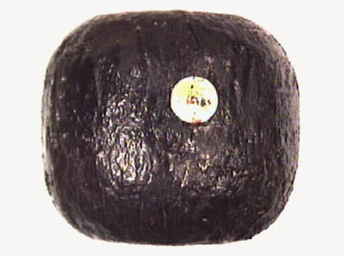
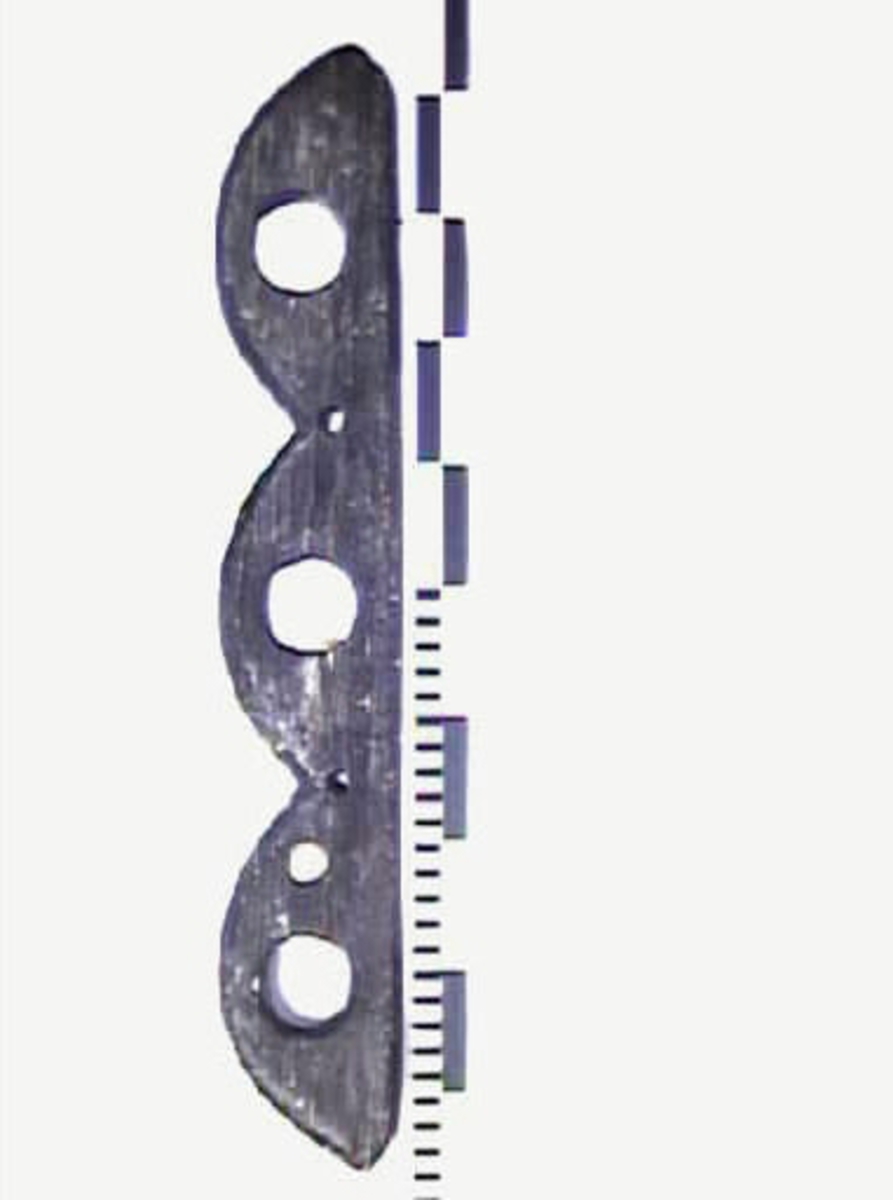
Here is a truck which might also be of interest:
There were a few interesting discussions going on based on entries in the finds database back in the day when Yahoo groups were the forums of choice.
For example find #23113 which is part of the sculpture some kit makers place on the beakhead bulkhead railing where it can't possibly fit due to the run of the main stay. Turned out it fits under the shield held by the figurehead lion.. :)


Cheers,
Peter
 
Last edited:
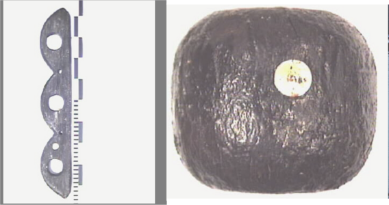
Many thanks Peter. I am very pleased to have a dimension of the 'truck' you have detailed from the Vasa. The truck dimensions shown has a diameter of 180mm (or 7.1 inches). At 1/75th scale, this requires beads to be 2.4mm. I have some of a size similar to this, and so I will use them for my parrels. For those who haven't seen the link, the rib and truck pictures are as below (not to scale):

1636691915711.png

The rib height is 920mm and is supposedly for a large yard (mainsail and lower foresail). The truck identified, is 180mm in diameter so I am assuming this is for a smaller yard (eg topgallant or topsail) equating to a scale 1/75 of 2.4mm bead size. On the previous calculations the larger parrel trucks are about a scaled 6mm!!

The text with the truck (in Swedish) I have translated and its description reads:

"A rack ball is a wooden ball with a through hole. Rack balls together with rack sleds and rope timber form a rack. Racks (parrels) were placed in a wreath around the masts and held the yards in place. When the yards were hoisted, the rack ball rolled along the mast like a ball bearing. In Vasa there were nine racks; three on the jib (fore) mast, three on the mainmast, two on the mezzanine (mizzen) mast and one on the snare bar (spritsail topmast). The number of rack balls and rack sleds in each rack varies based on the thickness of the mast. About 100 rack-balls have been found in Vasa. Some of these were reserves stored on deck or in the hull of the ship".

Very interesting - Thanks Peter Jennsen!!

PeterG
 
Last edited:
Many thanks Peter. I am very pleased to have a dimension of the 'truck' you have detailed from the Vasa. The truck dimensions shown has a diameter of 180mm (or 7.1 inches). at 1/75th scale, this requires beads to be 2.4mm. I have some of a size similar to this, and so I will use them for my parrels. For those who haven't seen the link, the rib and truck pictures are as below (Not to scale):

View attachment 268925

The only remaining question from the truck identified, is whether it is from a larger sail's yard (eg foresail or mainsail), or from a smaller yard (eg topgallant or topsail). As the rib shown in for a 3 truck arrangements, this suggests that the rib is for a larger yard, and so we could assume the truck is from the same, larger parrel, but there is no guarantee!! The text with the truck (in Swedish) I have translated and its description reads:

"A rack ball is a wooden ball with a through hole. Rack balls together with rack sleds and rope timber form a rack. Racks (parrels) were placed in a wreath around the masts and held the tubes in place. When the tubes were hoisted, the rack ball rolled along the mast like a ball bearing. In Vasa there were nine racks; three on the jib (fore) mast, three on the mainmast, two on the mezzanine (mizzen) mast and one on the snare bar. The number of rack balls and rack sleds in each rack varies based on the thickness of the mast. About 100 rack-balls have been found in Vasa. Some of these were reserves stored on decks or in the whole ship".

Very interesting - Thanks Peter Jennsen!!

PeterG
Hi Peter G,

Yes, some ribs were found in the fore starboard storage areas below deck, there are quite a few preserved.
And indeed, the three-hole ribs would be for the larger yards. Here is an example of a two hole rib:

I am still eagerly awaiting the Vasa II volume that will contain the rigging. It's been on the way for ten years now, I think..

There are always exceptions and differences in practices that makes it difficult to know how certain things were done on specific ships and the Vasa is no exception.
If you look at mast caps and how the yards are hoisted, it resembles a mix of English and Dutch practice. In some of the aforementioned discussions with Fred Hocker on Yahoo groups, we concluded that the Vasa was rigged on Scottish contract (as was all of the Swedish navy at the time, -Clerk family-) and there is actually a model of a Danish ship that can be relevant,
the Norske Løve ivory and silver model in Rosenborg Castle:
(This ship was also rigged by a Scotsman and shares several rigging features with Vasa which was an interesting point that Fred was going to follow up on, might be reflected in the rigging details in Vasa II..)

('snare bar' is a mistranslation. Should read spritsail topmast.)

Cheers,
Peter J
 
Last edited:
Back
Top