HEINRICH, WHAT, A FANTASTIC HISTORY LESSON, YOUR EXPLANATIONS ARE DONE VERY WELL, THIS ONE ON MY BUILDING LIST,,,,, SORRY JIM AND ZOLY WITH MY HEARING AND EYESIGHT YOU ARE OUT OF THE FIRST ROW LOL.Don
-

Win a Free Custom Engraved Brass Coin!!!
As a way to introduce our brass coins to the community, we will raffle off a free coin during the month of August. Follow link ABOVE for instructions for entering.
-

PRE-ORDER SHIPS IN SCALE TODAY!
The beloved Ships in Scale Magazine is back and charting a new course for 2026!
Discover new skills, new techniques, and new inspirations in every issue.
NOTE THAT OUR FIRST ISSUE WILL BE JAN/FEB 2026
You are using an out of date browser. It may not display this or other websites correctly.
You should upgrade or use an alternative browser.
You should upgrade or use an alternative browser.
VOC SPIEGELRETOURSCHIP BATAVIA 1628 - KOLDERSTOK 1:72
- Thread starter Heinrich
- Start date
- Watchers 64
-
- Tags
- batavia kolderstok
- Joined
- Jan 9, 2020
- Messages
- 10,566
- Points
- 938

@donfarr : Hello Donnie. I am very glad to see you are here. Thank you so much for all your kind comments. Yes, to me history is an important part of what we all love to do so much. I am fortunate that there is a wealth of information available on the Batavia and that the Haarlem does not really differ much from the Batavia.
- Joined
- Oct 30, 2018
- Messages
- 5
- Points
- 43

Hi,
There are many photos of the Batavia in Lelystad in summer 2003, showing lots of details
 www.modelships.de
There are many photos of the Batavia in Lelystad in summer 2003, showing lots of details
Batavia, a VOC ship of 1628
- Joined
- Jan 9, 2020
- Messages
- 10,566
- Points
- 938

Dear Friends
During the weekend I did not get as much work done as I would have liked due to work commitments and unfortunately this week does not look much better either. However, I did assemble the stern or Spiegel.
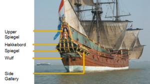
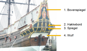
The term Spiegelschip is derived from the upper-and lower spiegels - two flat (or almost flat) surfaces that closed the stern of the ship. It has become accepted practice to refer to the complete stern of a Spiegelretourschip as the spiegel, but strictly speaking, this is not correct. In truth, the spiegel (3) only refers to the section between the “hakkebord” (2) directly above it and the “wulf” (4) directly below it. The “wulf”, in turn, is the curved section of cross-planking at the stern that is situated below the spiegel (4).
Boven Spiegel
The richly decorated upmost part of the spiegel is referred to in Dutch as the “boven” or upper spiegel (1). This part was usually reserved for the coat of arms of the city that was the ship’s homeport.

Image courtesy of Wikipedia.
In case of the Haarlem, the coat of arms consists of the crest which contains a red shield with silver sword and golden handle under a white Jerusalem cross and flanked by 4, six-pointed, white stars. Above the shield is the Imperial Crown of Austria underneath barren branches holding two Damiate bells. Underneath the crest appears the Latin inscription “Vicit Vim Virtus” which translated, means “Virtue Conquered Violence”.
The barren branches refer to the burned trees in the Haarlemmerhout, which were burned repeatedly during various sieges, most notably during the siege by the army of Jacqueline, Countess of Hainaut, in 1428.
The two bells refer to the Damiaatjes which were given to the St Bavochurch of Haarlem. These two bells ring every night between nine and nine-thirty, to signal the closing of the city’s gates and to commemorate the conquest of the Egyptian city of Damietta during the Siege of Damietta in 1218. Significantly, not only the bells, but also the sword and the Jerusalem cross owe their appearance on the coat of arms of Haarlem to the Siege of Damietta.
According to local legend, the original shield of Haarlem contained simply the four stars on a red background. However, as a result of an heroic cutting of the harbour chain of Damietta by a Haarlem “saw ship”, the Crusader-fleet was allowed to attack and conquer the city successfully. In recognition of the heroic deed, the Holy Roman Emperor granted Haarlem the usage of a sword and the Patriarch of Jerusalem granted the use of a cross. This story is known as the "Wapenvermeerdering", or "Addition to the Arms".

Both the Jerusalem Cross and the Sword owe their presence on the shield to the legendary cutting of the Harbour Chain at the Siege of Damietta in 1218.
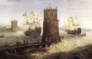
The capture of the Damiate. This painting by Cornelis Claesz von Wieringen, circa pre-1628, illustrates the cutting of the chain. (Frans Hals Museum, Haarlem).
During the weekend I did not get as much work done as I would have liked due to work commitments and unfortunately this week does not look much better either. However, I did assemble the stern or Spiegel.


The term Spiegelschip is derived from the upper-and lower spiegels - two flat (or almost flat) surfaces that closed the stern of the ship. It has become accepted practice to refer to the complete stern of a Spiegelretourschip as the spiegel, but strictly speaking, this is not correct. In truth, the spiegel (3) only refers to the section between the “hakkebord” (2) directly above it and the “wulf” (4) directly below it. The “wulf”, in turn, is the curved section of cross-planking at the stern that is situated below the spiegel (4).
Boven Spiegel
The richly decorated upmost part of the spiegel is referred to in Dutch as the “boven” or upper spiegel (1). This part was usually reserved for the coat of arms of the city that was the ship’s homeport.

Image courtesy of Wikipedia.
In case of the Haarlem, the coat of arms consists of the crest which contains a red shield with silver sword and golden handle under a white Jerusalem cross and flanked by 4, six-pointed, white stars. Above the shield is the Imperial Crown of Austria underneath barren branches holding two Damiate bells. Underneath the crest appears the Latin inscription “Vicit Vim Virtus” which translated, means “Virtue Conquered Violence”.
The barren branches refer to the burned trees in the Haarlemmerhout, which were burned repeatedly during various sieges, most notably during the siege by the army of Jacqueline, Countess of Hainaut, in 1428.
The two bells refer to the Damiaatjes which were given to the St Bavochurch of Haarlem. These two bells ring every night between nine and nine-thirty, to signal the closing of the city’s gates and to commemorate the conquest of the Egyptian city of Damietta during the Siege of Damietta in 1218. Significantly, not only the bells, but also the sword and the Jerusalem cross owe their appearance on the coat of arms of Haarlem to the Siege of Damietta.
According to local legend, the original shield of Haarlem contained simply the four stars on a red background. However, as a result of an heroic cutting of the harbour chain of Damietta by a Haarlem “saw ship”, the Crusader-fleet was allowed to attack and conquer the city successfully. In recognition of the heroic deed, the Holy Roman Emperor granted Haarlem the usage of a sword and the Patriarch of Jerusalem granted the use of a cross. This story is known as the "Wapenvermeerdering", or "Addition to the Arms".

Both the Jerusalem Cross and the Sword owe their presence on the shield to the legendary cutting of the Harbour Chain at the Siege of Damietta in 1218.

The capture of the Damiate. This painting by Cornelis Claesz von Wieringen, circa pre-1628, illustrates the cutting of the chain. (Frans Hals Museum, Haarlem).
- Joined
- Jan 9, 2020
- Messages
- 10,566
- Points
- 938

On the Kolderstok model the Spiegel or stern assembly consists of a number of parts which I will explain at the hand of photographs.
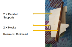
Firstly, the two parallel supports are glued to the rearmost bulkhead. The way that the slots are cut into the bulkhead and the angle of the supporting makes, it impossible to attach them at an incorrect angle. Fitment was, as usual, very tight with minimum sanding required.
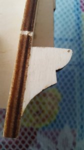
Two footpieces (one on either side) are attached to the bulkhead so that they line up with the edge of the bulkhead on both sides.
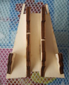
Viewed directly from the rear, the assembly of the rearmost bulkhead looks like this.
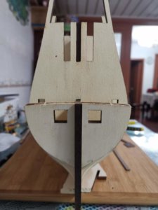
The lower part of the rear bulkhead (or wulf) which house the rear cannon ports are then slotted into its designated space in the hull. Fitment is as secure as one could possibly hope for.
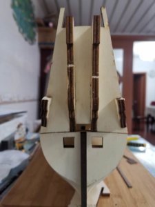
The upper part of the assembly, (the one that I showed the assembly of in the first three photographs is then hooked (via the two hooks shown in the first photograph) into the second from last bulkhead and slid into position. Testimony of the accuracy with which Kolderstok executes its laser-cutting is the alignment of the upper and lower parts - absolutely perfect!
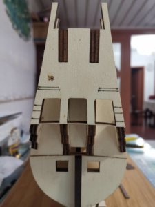
To this then is added the extreme or uppermost part of the Upper Spiegel assembly which will house the hakkebord and Bovenspiegel. This part will also play host to the coat of arms of the City of Haarlem. And, voila! Everything is done. For the time being, everything is dry-fitted because of three reasons:
1. On the Kolderstok model, the two rear gunports are designed to be closed, but I may choose to install cannons. This will obviously require some fiddling of parts.
2. Most model builders paint the rearward facing part of the last bulkhead black to create an illusion of depth when the windows are installed. I may still end up doing the same, but would first like to experiment with giving it a wooden finish.
3. The Wulf or lower part (which house the gunports) have to be planked vertically at an angle of 72 degrees. At this stage I am still contemplating if its not going to be easier to do while the wulf is not attached is to the ship.
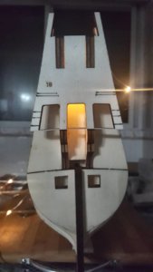
And just for some light relief, I also played around with some lighting after the work was done.
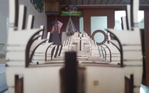
The last task of the weekend was regluing all the crossbeams (which had been removed earlier prior to the fitment of the help deck) back into their position. This photograph shows the absolutely perfect symmetry of the hull and alignment of the deck beams. At the conclusion of this phase, I remain a very happy and satisfied camper.
Thank you all for your interest and for following.
Kind regards - Heinrich

Firstly, the two parallel supports are glued to the rearmost bulkhead. The way that the slots are cut into the bulkhead and the angle of the supporting makes, it impossible to attach them at an incorrect angle. Fitment was, as usual, very tight with minimum sanding required.

Two footpieces (one on either side) are attached to the bulkhead so that they line up with the edge of the bulkhead on both sides.

Viewed directly from the rear, the assembly of the rearmost bulkhead looks like this.

The lower part of the rear bulkhead (or wulf) which house the rear cannon ports are then slotted into its designated space in the hull. Fitment is as secure as one could possibly hope for.

The upper part of the assembly, (the one that I showed the assembly of in the first three photographs is then hooked (via the two hooks shown in the first photograph) into the second from last bulkhead and slid into position. Testimony of the accuracy with which Kolderstok executes its laser-cutting is the alignment of the upper and lower parts - absolutely perfect!

To this then is added the extreme or uppermost part of the Upper Spiegel assembly which will house the hakkebord and Bovenspiegel. This part will also play host to the coat of arms of the City of Haarlem. And, voila! Everything is done. For the time being, everything is dry-fitted because of three reasons:
1. On the Kolderstok model, the two rear gunports are designed to be closed, but I may choose to install cannons. This will obviously require some fiddling of parts.
2. Most model builders paint the rearward facing part of the last bulkhead black to create an illusion of depth when the windows are installed. I may still end up doing the same, but would first like to experiment with giving it a wooden finish.
3. The Wulf or lower part (which house the gunports) have to be planked vertically at an angle of 72 degrees. At this stage I am still contemplating if its not going to be easier to do while the wulf is not attached is to the ship.

And just for some light relief, I also played around with some lighting after the work was done.

The last task of the weekend was regluing all the crossbeams (which had been removed earlier prior to the fitment of the help deck) back into their position. This photograph shows the absolutely perfect symmetry of the hull and alignment of the deck beams. At the conclusion of this phase, I remain a very happy and satisfied camper.
Thank you all for your interest and for following.
Kind regards - Heinrich
Great history lesson and progress Heinrich.
I like the way you are making the building log - very informative and interesting - please do not change your "style" 
- Joined
- Jan 9, 2020
- Messages
- 10,566
- Points
- 938

Thank you for your comments on the build log, Uwe. I am attempting to make it as informative as I can to help potential first-time builders. This is a daunting build, but luckily I get help from the Dutch forum; so I'm only too happy to pass that on here!
Kind regards-Heinrich
Kind regards-Heinrich
I agree with others. I like especially it seems how the frame/bulkheads are formed much better and fit very well. A very sturdy secure frame to build upon. I am reserving my seat too. I had been wanting to see this one built as well.
JUST A WONDERFUL BUILDING LOG, SO INFORMATIVE THE EXPLNATIONS ARE SPOT ON, AND I TOTALY AGREE WITH UWE DO NOT CHANGE IT Don
- Joined
- Jan 9, 2020
- Messages
- 10,566
- Points
- 938

Good morning everyone. Thank you so much for your kind comments. Dear Donnie, yes the frame is extremely sturdy and once the proper preparation had been done (mainly just some sanding), the parts fit together extremely well. This obviously results, like you say, in an extremely rigid and solid hull construction. Also, like I mentioned before, everything can be cross-checked easily to see that alignment is correct. So far I have not had to make a single adjustment to that. This just makes the builder so much more confident to move onto the next step.
- Joined
- Jan 9, 2020
- Messages
- 10,566
- Points
- 938

Dear Don, thank you very much for the comments on the style of the build log. I suppose the style comes from me being a teacher!  This is the only style I know, so I won't change anything!
I follow your Rochefort build log with great interest as well and remain amazed at the complexity that goes into that. So, best of luck with those frames!
Kind regards-Heinrich
I follow your Rochefort build log with great interest as well and remain amazed at the complexity that goes into that. So, best of luck with those frames!
Kind regards-Heinrich
THANKS HEINRICH, I am getting there with the frames materials should be in this week, so i can start to finish all the frames first phase, do need some advice on the jig/slip to see if it would work. Don
- Joined
- Jan 9, 2020
- Messages
- 10,566
- Points
- 938

Good afternoon everyone from a rainy and cold Nantong.
Well, it's been a week since my last post, so time for an update. As usual, thank you for all the kind words received so far and for following.
Phase 3 comprised of the installation of the gunwales, the construction of the cannon boxes and their corect placement on the gunwales. This was a task I was not looking forward to as it would see me try my hand at my first “plank-bending” exercise. And to add even more adrenalin was the fact that the “bending” was not only the normal bending that you would use when planking a hull, but also “vertical” bending. And true as Bob! The Batavia threw me its first curveball ... but more about that a bit later.
For the vertical bending part, I used the method as described by forum member, Glenn Barlow (Lady Nelson build), which, I must say, worked a cinch!. Thank you Glen! For the aspirant builders and newbies like myself, this just proves the value of being a forum member!
In a nutshell, I first immersed the planks in hot water for about a minute and thereafter laid it on its designated place on the full-scale plan. With the help of clamps or push pins (I used both methods, but the clamps work infinitely better) the wet plank is then shaped into its exact shape and curvature. After about 10 minutes, I “ironed” the planks with a steam iron. The steam worked well as it ensures that there is no scorching of the planks. While doing this, the planks visibly change colour as they become drier. Once done, leave the planks for another 10 minutes or so clamped and remove. Voila! You have a perfectly bent plank which can be glued immediately.
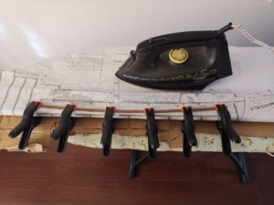
So with this successfully done, it now came down to the gunwales:
The instructions are very concise. Glue three 6mm x 1.5mm basswood planks on top of one another into their assigned slots provided for in the bulkheads. The slots in all bulkheads - except #13 - measures exactly 18mm which, of course, conforms to the added-up dimensions of the three 6mm planks. In the Dutch instructions it mentions that the planks “verspringen” at the stern which is translated in English as “the planks rise aft towards the stern”.
Unfortunately, this English translation falls short of explaining exactly what needs to be done, while the photographs in the instruction manual are not of great help. Even though I understand Dutch, I was unsure of the exact meaning of “verspringen” in this context and it took me a good few hours to figure out what was meant. The full scale drawings provided a good clue of what was meant, but even then, I still found it necessary to run my interpretation by some Dutch forum members first.
So, let’s see what is meant by “verspringen”. As usual, I will explain at the hand of some pics:
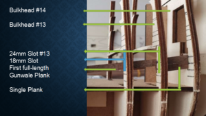
Above you will see that I mentioned the slots all measure 18mm except bulkhead 13 which measures 24mm. The idea is that a single and short plank is inserted from bulkhead #14 at the stern to bulkhead #13. The first and second full-length gunwale planks run from bulkhead #14 all the way and uninterrupted to bulkhead #3 at the stern. When it comes to the third gunwale plank, it starts its run from bulkhead #13 (not #14) and continues to the front to bulkhead #3. With that now understood, I inserted the short plank between bulkheads #14 & #13 and proceeded by gluing the first full-length gunwale plank into position.
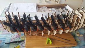
Clamping process.
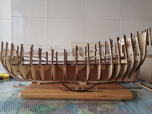
Full-length gunwale plank in position (view: port side). All good!
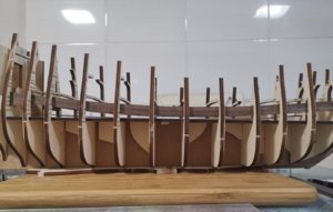
Second, full-length gunwale plank in position (starboard side). All good and very happy with there being no gaps between the two planks!
Third gunwale plank: CURVEBALL!!!
No matter how many times, I measured, the available space for the third plank was NOT 6mm - in fact, it was far less than that in some cases as small as 4mm. Sure I could plane the plank to 4mm, but I possess neither electric nor hand-planer and with 90% of all shops in China still closed because of the Coronavirus, I couldn't very well just go out and buy one. Trying to file or cut open the slots would result in too weak a joint between the bulkheads and deck beams and would also be negated by the height of the deck beams which prevented the planks from being slid higher up on the bulkheads. So I did the only thing I could think of. I glued a full-sized plank behind the first two gunwale planks to the maximum height it would go and made it run all the way from bulkhead #14 to #3 for maximum strength.
Obviously this means that the cannon port boxes will not sit flush all the way against the gunwales - there will be a 1.5mm (the thickness of the planks) gap between the back of the cannon boxes and the third plank, but there I will simply insert custom-cut pieces of planking as required. What I do have now are two gunwale sides that are immensely strong and solid being effectively double-planked.
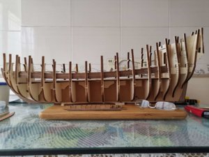
Final gunwale in position - viewed from port side.
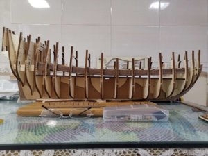
I must say, I am very happy with the angles as port and starboard sides follow an identical curvature. Also note in the above two photographs the extra bracing I have applied below the deck to the joints between the hull, bulkheads and deck.
Of course I contacted Hans from Kolderstok about the problem and he replied immediately. Hans commented as follows: "The nominal thickness of the walnut planks (which differ from supplier to supplier) may differ at times and affect the tolerances." He also said that he would incorporate the necessary changes to future kits where the slots will be enlarged to compensate for any variances.
Next up was the making of the cannon boxes - a fiddly and fidgety job, but one that I enjoy after all the headscratching with the gunwales. So far 13 have been completed - still 9 to go.
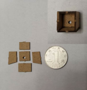
Cannon box parts are pictured next to a 1 Yuan coin for size comparison! When these are done, it will be time to measure out their exact positions on the gunwales, drill holes for the "push-in" cannons to fit and secure the gunboxes to the gunwales.
Thank you all for reading and following. This is all for now, I will be back - hopefully soon - with pictures of the installed cannons and gunboxes.
Kind regards-Heinrich
Well, it's been a week since my last post, so time for an update. As usual, thank you for all the kind words received so far and for following.
Phase 3 comprised of the installation of the gunwales, the construction of the cannon boxes and their corect placement on the gunwales. This was a task I was not looking forward to as it would see me try my hand at my first “plank-bending” exercise. And to add even more adrenalin was the fact that the “bending” was not only the normal bending that you would use when planking a hull, but also “vertical” bending. And true as Bob! The Batavia threw me its first curveball ... but more about that a bit later.
For the vertical bending part, I used the method as described by forum member, Glenn Barlow (Lady Nelson build), which, I must say, worked a cinch!. Thank you Glen! For the aspirant builders and newbies like myself, this just proves the value of being a forum member!
In a nutshell, I first immersed the planks in hot water for about a minute and thereafter laid it on its designated place on the full-scale plan. With the help of clamps or push pins (I used both methods, but the clamps work infinitely better) the wet plank is then shaped into its exact shape and curvature. After about 10 minutes, I “ironed” the planks with a steam iron. The steam worked well as it ensures that there is no scorching of the planks. While doing this, the planks visibly change colour as they become drier. Once done, leave the planks for another 10 minutes or so clamped and remove. Voila! You have a perfectly bent plank which can be glued immediately.

So with this successfully done, it now came down to the gunwales:
The instructions are very concise. Glue three 6mm x 1.5mm basswood planks on top of one another into their assigned slots provided for in the bulkheads. The slots in all bulkheads - except #13 - measures exactly 18mm which, of course, conforms to the added-up dimensions of the three 6mm planks. In the Dutch instructions it mentions that the planks “verspringen” at the stern which is translated in English as “the planks rise aft towards the stern”.
Unfortunately, this English translation falls short of explaining exactly what needs to be done, while the photographs in the instruction manual are not of great help. Even though I understand Dutch, I was unsure of the exact meaning of “verspringen” in this context and it took me a good few hours to figure out what was meant. The full scale drawings provided a good clue of what was meant, but even then, I still found it necessary to run my interpretation by some Dutch forum members first.
So, let’s see what is meant by “verspringen”. As usual, I will explain at the hand of some pics:

Above you will see that I mentioned the slots all measure 18mm except bulkhead 13 which measures 24mm. The idea is that a single and short plank is inserted from bulkhead #14 at the stern to bulkhead #13. The first and second full-length gunwale planks run from bulkhead #14 all the way and uninterrupted to bulkhead #3 at the stern. When it comes to the third gunwale plank, it starts its run from bulkhead #13 (not #14) and continues to the front to bulkhead #3. With that now understood, I inserted the short plank between bulkheads #14 & #13 and proceeded by gluing the first full-length gunwale plank into position.

Clamping process.

Full-length gunwale plank in position (view: port side). All good!

Second, full-length gunwale plank in position (starboard side). All good and very happy with there being no gaps between the two planks!
Third gunwale plank: CURVEBALL!!!
No matter how many times, I measured, the available space for the third plank was NOT 6mm - in fact, it was far less than that in some cases as small as 4mm. Sure I could plane the plank to 4mm, but I possess neither electric nor hand-planer and with 90% of all shops in China still closed because of the Coronavirus, I couldn't very well just go out and buy one. Trying to file or cut open the slots would result in too weak a joint between the bulkheads and deck beams and would also be negated by the height of the deck beams which prevented the planks from being slid higher up on the bulkheads. So I did the only thing I could think of. I glued a full-sized plank behind the first two gunwale planks to the maximum height it would go and made it run all the way from bulkhead #14 to #3 for maximum strength.
Obviously this means that the cannon port boxes will not sit flush all the way against the gunwales - there will be a 1.5mm (the thickness of the planks) gap between the back of the cannon boxes and the third plank, but there I will simply insert custom-cut pieces of planking as required. What I do have now are two gunwale sides that are immensely strong and solid being effectively double-planked.

Final gunwale in position - viewed from port side.

I must say, I am very happy with the angles as port and starboard sides follow an identical curvature. Also note in the above two photographs the extra bracing I have applied below the deck to the joints between the hull, bulkheads and deck.
Of course I contacted Hans from Kolderstok about the problem and he replied immediately. Hans commented as follows: "The nominal thickness of the walnut planks (which differ from supplier to supplier) may differ at times and affect the tolerances." He also said that he would incorporate the necessary changes to future kits where the slots will be enlarged to compensate for any variances.
Next up was the making of the cannon boxes - a fiddly and fidgety job, but one that I enjoy after all the headscratching with the gunwales. So far 13 have been completed - still 9 to go.

Cannon box parts are pictured next to a 1 Yuan coin for size comparison! When these are done, it will be time to measure out their exact positions on the gunwales, drill holes for the "push-in" cannons to fit and secure the gunboxes to the gunwales.
Thank you all for reading and following. This is all for now, I will be back - hopefully soon - with pictures of the installed cannons and gunboxes.
Kind regards-Heinrich
Heinrich,
Excellent explanation of your “CURVEBALL”. I’m really enjoying following your log.
Jan
Excellent explanation of your “CURVEBALL”. I’m really enjoying following your log.
Jan
- Joined
- Jan 9, 2020
- Messages
- 10,566
- Points
- 938

Hi Jan. Thank you very much for your kind words. I try to share as much as I can - the good and the curveballs! - in an attempt to make sure that aspirant builders find the build as easy as possible.
Kind greetings - Heinrich
Kind greetings - Heinrich
The supplier of the planks always informs me that there are slight differences in width and thickness of the planks, due to the sawing process. Obviously here the planks are a bit wider as the 6 mm they should be. You have solved it in a nice way. This gunwale plank is only the base for the gunports and disappears after gluing the gunports and hullplanking into position.
There are two solutions for me to improve the kit on this gunwale plank:
- make the slots in the frame a bit wider so the planks will still fit. But this has the risk of weakening the frames at the upper side.
- add a laser cut piece of 1 mm mdf in the kit in the right dimension and form of the gunwale plank. This also solves the "problem" with the Dutch word "verspringen" (for which even my English brother-in-law could not find an exact translation to English. He came up with "stagger" which comes the most close to it, but not completely to what was mend)


