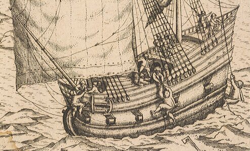
Willem Barentsz by Kolderstok AD 1596

If you can hum while cutting out gunports, you are a better man than I. ROTF
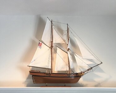
That is going to be an interesting event. The only gun ports i’ve cut out to date were on my first build a couple years ago. That kit was my introduction to this hobby.


6EA3AD34-85B2-4C3E-8DA2-3E4F9E55A6E1.jpeg

It sits on my fireplace mantle proudly displaying every mistake a novice modeler could make.
 
(Oh, it definitely gets better; you're gonna be building your second WB a lot sooner than you think and the beauty of it is that you won't have to use the money from your bad word jar to do so.)

Could be, could be. But I have the Duyfken waiting to be planked, a sternwheeler waiting to have the fancy bling installed and I have Pavils Galleon on the way. So……
 
Last edited:
(Oh, it definitely gets better; you're gonna be building your second WB a lot sooner than you think and the beauty of it is that you won't have to use the money from your bad word jar to do so.)

Could be, could be. But I have the Duyfken waiting to be planked, a sternwheeler waiting to have the fancy bling installed and I have Pavils Galleon on the way. So……
I'm afraid that's what you think, my guess is the ladies might have diametrically opposed priorities...
 
That is going to be an interesting event. The only gun ports i’ve cut out to date were on my first build a couple years ago. That kit was my introduction to this hobby.


View attachment 328078

It sits on my fireplace mantle proudly displaying every mistake a novice modeler could make.
Beautiful Jan. Our first model always has a special place in our hearts- warts and all. When I finish my Victory one day (warts and all) in the distant future she will always be proudly displayed as my first. Cheers Grant
 
Beautiful Jan. Our first model always has a special place in our hearts- warts and all. When I finish my Victory one day (warts and all) in the distant future she will always be proudly displayed as my first. Cheers Grant
I look at the model as a cumulative number of mistakes bonded by glue into a final result. Visitors see a ship model on display. So I would expect that “Grants Victory“ will be admired in a similar fashion.
 
A Wale of a problem.

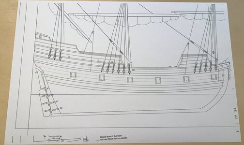
Step one, make a copy of the plan to get gun port positions.

EAB52E17-C859-4676-9777-C6668E9F677F_1_201_a.jpeg

Plan printed on 11 X 17 inch paper.

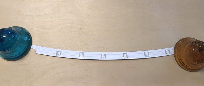
Step two, paste copy to heavy duty card stock and cut out gun port portion as a template.


9A830770-98A4-4CE1-BFFE-7DED46B111B2_1_201_a.jpeg

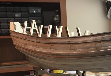
Step three, lay template on hull, realizing going from 2D to 3D it won't be a perfect fit.

3BD28E1C-E098-443A-B688-AFE3BEDFC2AD_1_201_a.jpeg

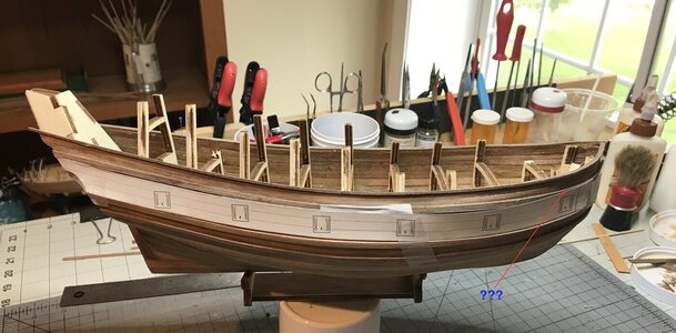
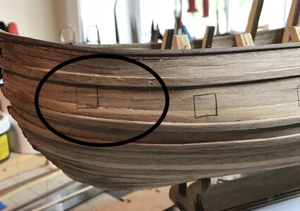
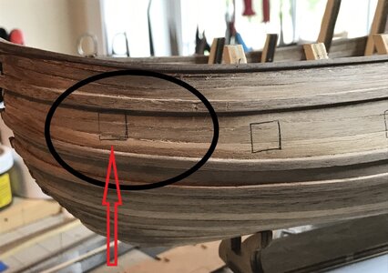
The RO-OH moment. A little bitty problem at the bow. Assuming the the wale below the gun port is right then the wale above must be moved up???

@Heinrich, where did I go wrong???
 
Jan, are you saying that there is not enough room between the two wales for the port closest to the bow?
 
Jan, are you saying that there is not enough room between the two wales for the port closest to the bow?


Yup, I think that portion of the Wale has to move up just a wee bit. I never noticed the difference at the bow between the Wale and the cap rail until this morning. But it's an easy fix. I won't cut in that gun port until I finish cutting/sanding the bow for the Stem fit.

All the other gun port outlines look good to me.

BED57850-7B63-416E-88D9-03448DDA3A4C_1_201_a.jpeg
8CB31F9C-117E-41E9-805F-F45CAEC9D5B6_1_201_a.jpeg
 
Yup, I think that portion of the Wale has to move up just a wee bit. I never noticed the difference at the bow between the Wale and the cap rail until this morning. But it's an easy fix. I won't cut in that gun port until I finish cutting/sanding the bow for the Stem fit.

All the other gun port outlines look good to me.

View attachment 328224
View attachment 328225
Hi Jan. Cut out 6 paper squares and keep on projecting (with some tape) on your hull till you are satisfied. Take your time!
(The projected curve of the bow is not in the right length on the 2D drawing.)
Regards, Peter
 
I'm not so sure Jan. Look how Heinrich oriented his port openings:

View attachment 328231
They track a bit more with the curvature of the wales than what you have drawn...
I think you have captured some distortion: you took a curvy thing and rendered it onto a flat sheet of paper/cardboard and then put it back on a curvy thing...
It's not really much of a worry . The upper Wale needs to move a bit up at the bow to match the space between it and the cap rail as it sits along the hull. The gun port as marked is a wee bit to high and can be adjusted down. It won't be open so there are no port doors to worry about. I agree that using a 2D drawing as a template does make for 3D curvy dingus problems. I was just surprised that I had not noticed the incorrect spacing of the Wale at the bow. Too much sniffing of PVA fumes. :p
 
OK - small tutorial about the gunports.

First thing to remember - as already said: a 2D drawing is rather difficult to project on a 3D object. And the other way round: making a 2D drawing from an 3D object is also a bit of a thing (I know from experience).

Second: the drawing is first of all ment to give a guideline where the ports should come.

Third: How were ports cut in a ships hull? I wasn't there around 1595, but I presume (guess might be a better word) it was done in the following way.

The frames of the hull were all vertical in a 90 degree angle with the waterline. So the vertical sides of the ports were cut out as first. You simply had to cut in between the frames.
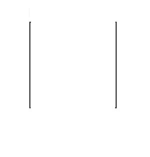
Gunport1.jpg

Second step is to cut out the upper joint - perpendicular to the vertical joints.
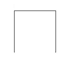
Gunport2.jpg

At this point the hinges could be mounted, so the lid would not fall out, and then the lower cut could be made.
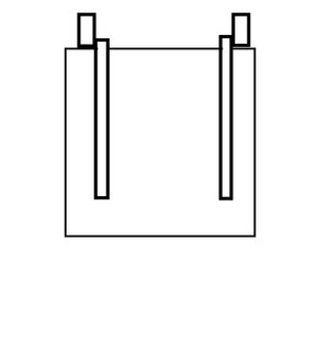
Gunport5.jpg

This lower joint did not have to be perpendicular to the other joints. The port would also open if it was under an angle:
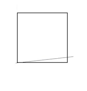
Gunport4.jpg

If the upper joint is cut in an angle with the vertical joints, remember that the hinges must be under this angle as wel, otherwise the ports can't be opened.

This works:
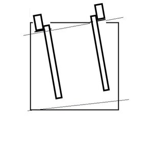
Gunport6.jpg

This certainly not!:

Gunport8.jpg

The easiest way to project the ports is to cut a square in the right dimensions, pin it on the right spot on the hull and mark the outlines. Eventually you can follow the lines of the wales, but be aware how to place the hinges in this case.

Edit: the thinner lines in the sketches should be seen as joints instead of the thicker horizontal lines.

Hans
 
This is an excellent discussion, guys. Every single contribution that has been made, is correct! @dockattner Paul is correct in saying that my ports track with the curvature of the hull - that is why the "reading" of the hull is so important. @Peter Voogt Peter is also correct in saying that cutting out squares and then arranging them according to the wales, will yield a good result. Lastly, @Kolderstok Hans is also on the money about the process on how the ports were cut out and how they function (Hans only pretends not to have been around in 1596 - he knows too much not to have been! ROTF )

However, there is one point that has not been mentioned. Remember what I have referred to as a "pinched" effect of the wales at the bow? In other words, Jan, the wales do close up towards the stem - they are not equally spaced. (Look at my favorite drawing below)

1977_65.jpg

BED57850-7B63-416E-88D9-03448DDA3A4C_1_201_a.jpg
I believe there is nothing wrong with the wales. I would just juggle the port closest to the bow so that it sits more or less between the wales.
 
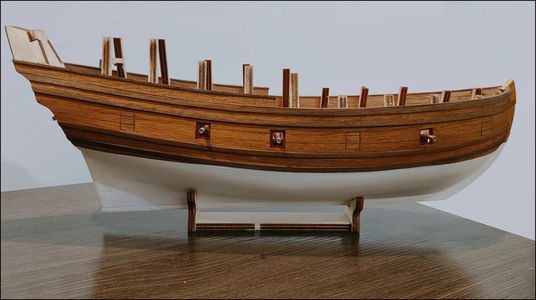
@Kolderstok, @Heinrich, Wow, that is a lot of information to absorb. Thank you guys for all the input. I did juggle the port closest to the bow down and left the Wale as is.
Good morning Jan. I agree with this call. When I looked at the top wale it looks correct. Awesome tutorial by Hans and Heinrich. Cheers Grant
 
Back
Top