Willem Barentsz by Kolderstok AD 1596

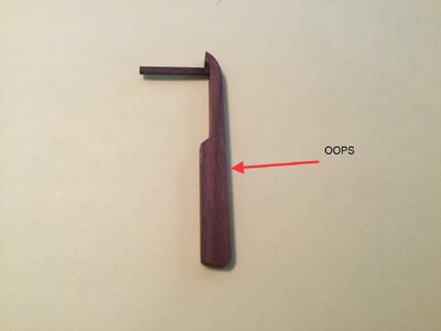
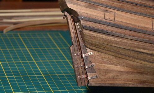
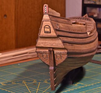
Yup, got on the wrong side of the front edge. I think a good fix is adding a couple of 1mm pieces to each side and then tapering the right “front” edge.

I noticed the problem this morning when got ready to scribe the vertical plank lines into the rudder. We will see how the “Re-Do” works.

Jan
That should do the trick, Jan - that is what I was also going to suggest. I don't know if you plan on painting the hull still - if you do, then most of the rudder will be painted in any case.
 
That should do the trick, Jan - that is what I was also going to suggest. I don't know if you plan on painting the hull still - if you do, then most of the rudder will be painted in any case.
The hull painting is waiting for warmer weather. I paint in the garage and it’s still a wee bit chilly out there.
 
The Rudder.

Before with the taper at the wrong side
IMG_3261.jpeg

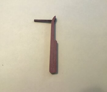
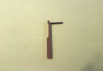
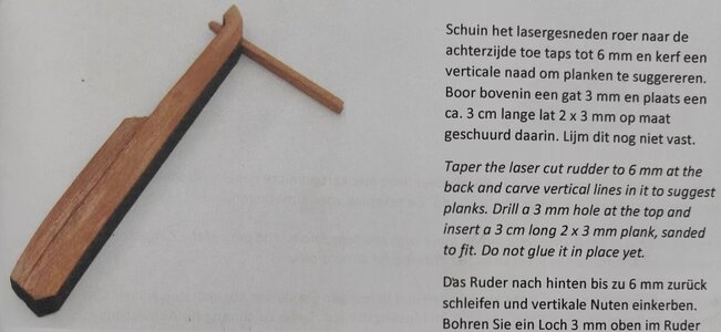
The error was corrected by laminating 0.5 mm pieces to bring the end with the arrow back to 8mm thickness, then sanding the back to a taper to about 6.5mm. The build instructions indicate a taper width of 6mm for the end. I went with "as close as I could get" without sanding away the the strips that I added.

The result.

IMG_4260.jpeg
IMG_4259.jpeg

Jan
 
The Rudder.

Before with the taper at the wrong side
View attachment 436121

The error was corrected by laminating 0.5 mm pieces to bring the end with the arrow back to 8mm thickness, then sanding the back to a taper to about 6.5mm. The build instructions indicate a taper width of 6mm for the end. I went with "as close as I could get" without sanding away the the strips that I added.

The result.

View attachment 436125
View attachment 436126

Jan
Good morning Jan. No isssues now- great fix. Cheers Grant
 
Jan, forgive my ignorence, but i don't get it completely.
In photo nr 1 you say that you corrected the taper on the wrong side ( at the red arrow )
In photo nr 2 and 3, you show your rudder, with the corrected tapering, but also with your tiller pointng the other way around??
If you changed the position of the tiller ( wich was a corect fix by the way ) then your old tapering was corect and now you tapered the wrong side???
because the tapering should be on the side of the rudder that is sitting against your sternpost. please correct me if i am wrong.
If Jan will allow me to answer ... apologies, Jan, for jumping in here ...

Not according to the instruction manual my friend.

微信图片_20240320225527.jpg

The following pics show @pietsan Piet's installation:

JPG_1628_6341_bewerkt-1.jpg
JPG_1632_6342_bewerkt-1.jpg
JPG_1634_6343_bewerkt-1.jpg
 
If Jan will allow me to answer ... apologies, Jan, for jumping in here ...

Not according to the instruction manual my friend.
Heinrich, many thanks for your answer, i was a bit confused about this, @Pathfinder65 did it completely according to the instructions, but i am glad that you showed the photo's of Pietsan, on that photo's you can see that he (pietsan) gave his own little twist to the instructions by placing that smaller plank at the frontside of the rudder, so he created a sort of tapering between the rudder and the sternpost.
Perhaps that tapering was not necessary on ships of that era, I'llhave a look in my books about this, and than i will give you a pm about what i found.
 
Ah, those pesky deadeyes. Working a bit here and there this week as time allows. I seem to be making progress.

View attachment 436558
View attachment 436559

That is ten of the twenty eight deadeyes that mount on the hull. I’m getting there one knot at a time.

Jan
Good evening Jan. They are coming together nicely. It’s like eating an elephant….one bite at a time…Cheers Grant
 
Jan, the translations you will have to do yourself! ROTF

@pietsan Piet Sanders

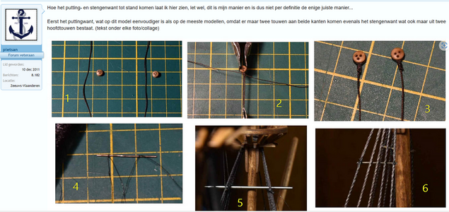
Hoe het putting- en stengenwant tot stand komen laat ik hier zien, let wel, dit is mijn manier en is dus niet per definitie de enige juiste manier...

Eerst het puttingwant, wat op dit model eenvoudiger is als op de meeste modellen, omdat er maar twee touwen aan beide kanten komen evenals het stengenwant wat ook maar uit twee hoofdtouwen bestaat. (tekst onder elke foto/collage)
Piet 1.png

(1), nodig twee garens van (in mijn geval) 0,25 mm dik en ong. 150 mm lang en twee juffers van 3 mm. De touwen voor het putting- en stengenwant zijn de helft dunner dan de hoofdtouwen van de mast zelf. (2), het touw voor het puttingwant word met een bindsel om de juffer(s) gelegd zoals te zien op plaatje (3). (4) de spreeworst maak ik van een stukje donker ijzerdraad wat in het pakket van het model zit, je kan hiervoor ook een stukje dikker touw gedrenkt in lijm voor nemen, de lijm zorgt ervoor dat het touw hard word. Hier worden twee dunne draadjes (één-tiende mm) aan geknoopt met een mastworpje ter hoogte van de twee buitenste hoofdtouwen. (5) de positie van de 2e spreeworst word met een recht item bepaald zodat beide gelijk liggen. (6) de spreeworst word aan de buitenste hoofdtouwen geknoopt met de twee draadjes uit plaatje 4 en geborgd met een drupje lijm.
De eindjes van de spreeworst worden afgeknipt met een kniptangetje, gelijk met de buitenste hoofdtouwen.
Piet 2.png

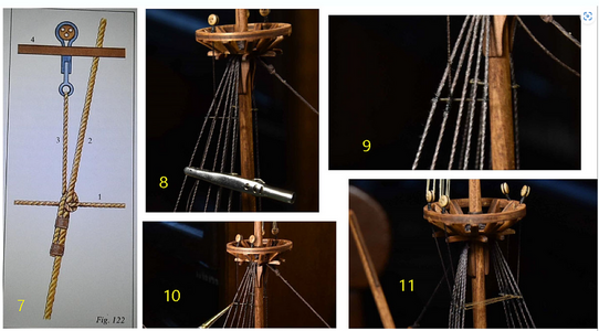
Het touw voor het puttingwant word door één van de gaatjes op de mastring gestoken (8) en met een halve slag om het 2e hoofdtouw en de spreeworst gelegd zoals te zien op de tekening (7) waar 1 de spreeworst is, 2 het hoofdtouw, 3 het touw voor het puttingwant en 4 de mastring. Het puttingwant word strak gezet, zodanig dat het hoofdtouw net niet naar buiten word getrokken en vast gezet met een klemmetje ook te zien op plaatje 8. (9) het touw voor het puttingwant word direct onder de spreeworst vast gemaakt aan het hoofdtouw met een bindsel van het zelfde dunne draad, dit voorkomt een lelijke dikke knoop ter plaatse. (10) de spreeworst word bij getipt met hennep kleurige verf. (11) een kleine zwichting zorgt ervoor dat bij het afspannen van het stengenwant de hoofdtouwen niet naar buiten worden getrokken.

And this is why Piet is unequalled as a model builder!
 
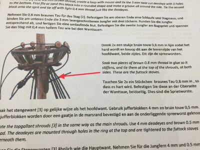
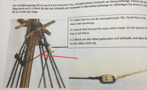
OK a Novice question.

I understand this part of the build. (red arrow).

View attachment 436714

But I can't find a reference for this. (red arrow)

View attachment 436715

Jan
Ehhh, small mistake in the instructions…
The red arrow should point at the block you see, to indicator where the instructions are about. I have to correct that in the manual.
Nevertheless now you also know what purpose the other thread has :-)
 
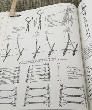
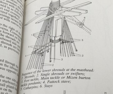
Aha, found the answer in Wolfram’s book.

Those are CATHARPINS, used between the Futtock shrouds.

View attachment 436752

View attachment 436753

Another technical term learned.

Jan
Good afternoon Jan. Yep catharpins. My Victory had plenty. I found them quite difficult to get right using the authentic knots to the shrouds. The key is the tension. You don’t want them pull the shrouds in while keeping the tension sufficient for them not to sag. Have fun :D . I have Spar swear jar for youROTF. Cheers Grant
 
Good afternoon Jan. Yep catharpins. My Victory had plenty. I found them quite difficult to get right using the authentic knots to the shrouds. The key is the tension. You don’t want them pull the shrouds in while keeping the tension sufficient for them not to sag. Have fun :D . I have Spar swear jar for youROTF. Cheers Grant
Ugh, I need more nimble fingers and better eyesight. I appreciate the offer of the Spar swear jar, but I think I’ll box up the kit and send it to Heinrich’s Anna. I think I have enough stashed in my bad word jar to do that. Knot tying, shrouds and deadeyes is definitely trying my patience.
Ehhh, small mistake in the instructions…
The red arrow should point at the block you see, to indicator where the instructions are about. I have to correct that in the manual.
Nevertheless now you also know what purpose the other thread has :)
My curiosity was piqued by that picture. You are right, with a little bit of research I found the answer.

Jan
 
Back
Top