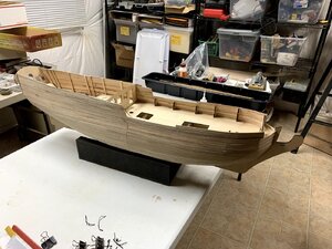
Just a quick update. I've completed the first layer of planking on the starboard side.

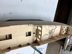
If you look closely on the deck you will see some loose wires. Most of those wires have a very tiny LED on the end. There are two that have a small, square circuit board with a small LED in the center. The ones with the LED only on the end will become lights on the bulwarks of the two great cabin rooms. There will be three such lights in the aft room and two in the forward room. There are also 3 LED type lights that will come out the stern transom for the 3 lanterns on the transom. The two small circuit board lights will hang from the ceiling, one in each room in a larger type of light. There's also one of those lights in the main deck area that will go under the forecastle deck.
The lights are made by Woodland Scenics and are called Just Plug. They each have a small plug on the end of them. The resistor needed to operate the lights is part of the light itself covered by a piece of black shrink wrap. There's a master unit (box type) with four sockets for plugs. Each socket has a small knob that allows you to adjust the brightness of the LED's. You can only plug 4 lights into this main control box. However, instead of lights, you can plug a small sub-box into each of the 4 sockets and each of those sub-boxes can have 4 lights plugged into it. That's the route I took on my lighting which enables me to control 4 sets of lights for a total of 16 lights. However, I won't be using all 16 available sockets in the four sub-boxes.
I routed all of the wires to one of two locations at the bottom of two different bulkheads. One bulkhead is at the fore end of the hull and the other is at the aft end. At those two locations, the wires come out of the hull and down through a trough I carved out of the keel that will be covered over with the thin layer of laser cut parts designed to give the keel a more finished look. Those who are building the model will know what I'm talking about.
I plan to route the wires through hollowed areas in a cradle foot, one at each end. Then the wires will pass through a hole in the base and towards the front of the base where they will enter a box I plan to build that will house the control box with the four knobs to control the brightness of the lights. This entire setup is powered by an AC to DC converter type power supply which will be plugged into an outlet behind the table I'm setting the model on. I did a lot of research on lighting and this is the route I decided to take because it's modular and you can grow it easily. I also didn't want to fool with batteries hidden inside the model that had to be changed from time to time.
Here's a photo of the deck area showing all the LED's with wires coming out of the side of the bulwarks where they will be hidden inside the bulwarks.

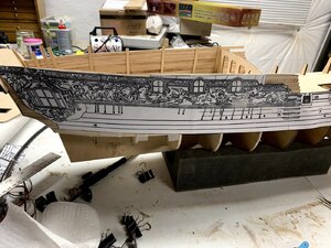
The last image shows how I finally figured out the carvings. The paper template was cut from two different sheets of plans and taped together.

The carvings gave me a fit because of two reasons. First of all, the large side gallery window is actually larger than what is shown in this drawing. As you can see in the drawing, the bottom of the carving dips below the upper wale. In reality, it comes down to the second wale.
There are a lot of relationships between the carvings and other parts of the model. There are relationships to the wales in the case of the gallery windows carvings. There are relationships to the three windows in the great cabins and atrium between them. There is a relationship to the upper and lower mouldings above and below the carvings, When I started to lay the carvings out, I discovered an anomaly with the middle carving.There is a ribbon that flows up and down in the air beneath the middle window shown in the drawing above.
The problem for me was that that middle carving in my kit had additional parts to that ribbon and those parts interfered with the placement of that middle window. What I determined was that the carving itself had extra ribbons in it that should not have been there, and as a result, I could not get that carving to line up properly in relationship to the other carvings and to the middle window. Once I figured that out, I used my X-acto knife to cut the extra ribbons out completely which also required me to reshape the one remaining ribbon shown in the drawing.
After I made that adjustment, things began to come together. I needed to do this exercise because I needed to establish the top of the bulwarks, especially the added area where the two great cabins are. As you can see in this photo, I have trimmed the top of the bulwarks to match the top lines of the drawing except at the fore end which I will do when I add the second layer of planking and the final carvngs.
I say "final carvings" because what I also discovered is that the carvings have a lot of extra wood around their edges that I have to trim away very carefully. There's also the debate as to whether or not to trim away the clouds in the carvings as Maarten did and paint the clouds onto the blue background. Right now I'm leaning in the direction to leave the clouds in the carvings and paint them a light gray color.
I've also made the decision to paint my carvings gold with a heavy black wash over them to bring out the details in the carvings. I'm going for a more historically correct look because I believe that the real ship had the carvings gilded, not left natural, or they may have been painted in a fashion similar to the Wasa which we now know were painted instead of being gilded. In any event, I just like the look of the gold carvings which I saw in a POF version of the model scratch built in 1/2" scale so that's the route I'm going to take. I bought some special gold paint that is suppose to be more shiny than something like Testor's gold paint used by plastic model builders.
So I'm now planking the port side with the first layer of planking. That will take several more days to do. Then it's sand, sand, sand before applying a coat of Elmer's wood filler and sanding it out before moving on to the second layer of planking.
One other thing I plan to do is to make panels using 1/16" plywood as their base to attach the interior bulwark planking and trim work. That way I can just install the individual panels onto the 1/16" thick strips I applied to the outer bulwarks interior when I cut off the upper portions of the bulkheads. That will enable me to leave most of the space between the outer hull planking and inner bulwarks void for the wiring and lights. I know it probably all sounds a bit confusing right now but in due time, you'll all see how I handled these things. I've been planning this build for well over a year before I ever bought the model, researching and studying other build logs I've found across the internet.
Oh, and I'd also like to mention that I'm finished with the carpet drawings for the aft cabin. Now all I have to do is plank the sunburst pattern shown in the plans the same way I did the fore cabin deck.
Take care,
Bob
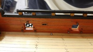
 It's coming along, slowly but surely. I've been planking the lower hull lately. Got both sides of the upper hull done from the wales up. Got to drill some holes in the deck sides though to pass the lighting wiring through before I close up the lower hull with planking. We'll post more photos in about a week.


