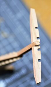
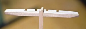
The Naval Cutter ALERT- 1777, POF by Jimsky

Many thanks, @Norway Knut, @JohnA John and all for the compliments and likes! :)

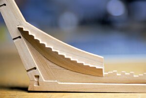
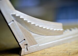
Continue with the false keel assembly, and today we actually moving to 'Apron' (or false post). It is consists of two parts: the upper section part BL7 and lover section part BL8. To complete this assembly we will need the rising wood part BL9.
Actually, I am learning the names of those parts alone with you! It is a great way to learn various ship parts. The parts identification can be found on page 6 of the instruction manual.

Assembly doesn't require special instructions. Once you release and clean from the timber board lightly sand and glue together. *IMPORTANT: To ensure the full alignment of all glued parts, use the template (part C52)! As I mentioned earlier, in Poul's @PoulD, response, I use black pencil 'B' to simulate caulking. Here is how it looks after assembly.
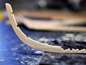
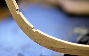
600_0666.jpg

600_0668.jpg

adding rising wood (part BL9)

600_0667.jpg

Aliment of all gluing parts can be archived by using a template (C52).
600_0658.jpg

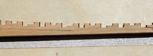
Both rising woods: false keel and apron
600_0661.jpg

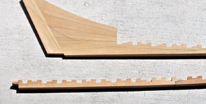
The apron a bit blurry, I am still learning photography.
600_0675.jpg

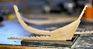
Finally, the entire assembly. The instruction suggests beveling the 'rabbet line' Will discuss this the next time.

600_0693.jpg

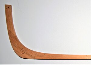
Stay tuned, to be continued...
 
I am glad that you find this build log interesting and would like to thank everyone for comments and likes!!! This is my first POF build and I am learning along with you. :)

...and we continue. Today, we will finish the kill structure and will make the stem and stern risers.
Stempost consists of three parts: Stempost - upper section (Part BL1), Stempost - lover section (Part BL2), and Fore foot (Part BL3). The parts were removed from timbers' frets, lightly sanded, and glued together. To ensure the proper alignment I use the template (part C52).
The book AOS (The Naval Cater Alert) shows the lower section of the stem and fore section of the keel (Part BL4) should be 'Boxing' together. However, in the kit version, this was simplified but fitted very well!

600_0694_1.jpg

The next step to glue together all three parts BL4, BL5, and BL6. This will complete the keel assembly. The kit doesn't provide the keel scarphs between BL4 and BL5, as well as between BL5 and BL6 as shown in the book. So...great care should be taken when gluing together. Use glass (straight and even surface) and template C52 when positioning all the parts.

600_0694.jpg

Now it is time to make a rabbet. Both keel and the false keel (instruction manual page 6). Instruction called the 'bilateral chamber'. This can be easily done using a construction cutter blade. Hold the keel on the flat surface and slowly move along the edge. Don't press too hard, and scrape a little per single move. DON'T move back and forth, One way only!! Change each side alternatively so you remove the same amount of wood from each side.

Once both keel and false keel rabbet line established, glue them together. Ideally, all the notches from the rising wood (false keel) have to match the notches from template C52 and the entire assembly should fit in the template without force.

600_0692.jpg

600_0678.jpg

600_0680.jpg

Here is how the completed keel looks now.

600_0703.jpg

600_0701.jpg

600_0700.jpg

to be continued...
 
Continue from the post #87

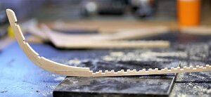
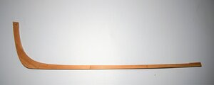
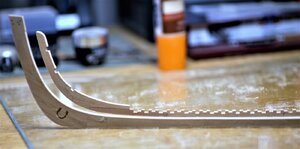
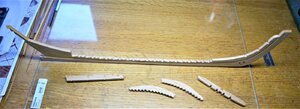
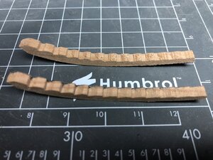
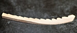
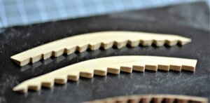
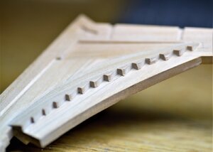
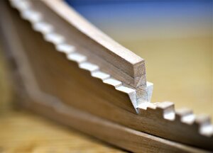
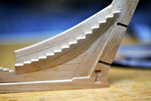
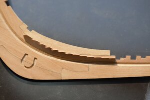
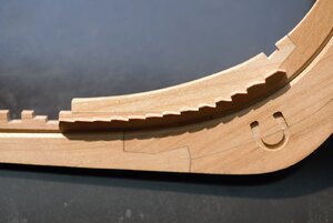
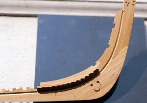
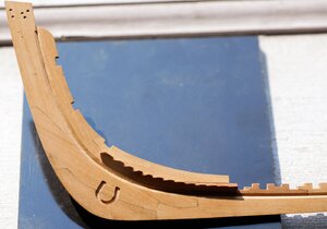
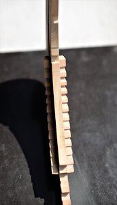
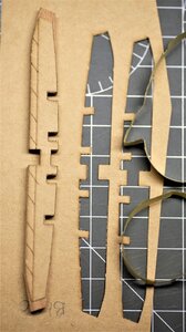
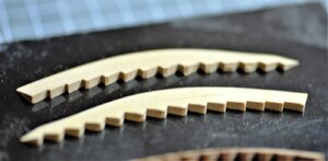
We are pretty much done with the entire keel assembly, we only left with two parts BL34 and BL33. Both parts are rising wood for the Stern and Stem. In real ships, those were part of the deadwood and comes as a single piece. Trident simplifies for us and makes them as two parts. The trick is they have to be shaped first before gluing on to the keel.

600_0713.jpg

When removing those parts from fret, the greatest care should be taken to avoid 'nocking the top of the notches. The stern pieces were of good quality and required only shaping. One of the stem pieces was damaged by the CNC cutting tool (the first from the top).

IMG_1573.JPEG

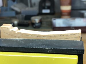
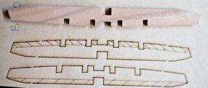
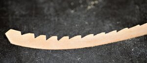
I would try to fix it... but realized, it will require removing a lot of wood and would completely change the size. So... we all strive to be scratch modelers... right? I made one from scratch... Just to make sure they are identical I cut them together as a single piece. I glue (corners) of both pieces and transfer the shape. Notches lines were outlined using fine teeth saw and the rest cut with a hobby knife.

IMG_1570.JPEG

IMG_1574.JPEG

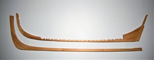
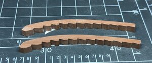
Here are both: the kit and scratch built from Pear.

IMG_1571.JPEG

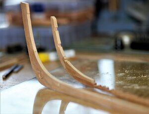
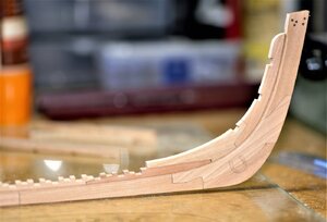
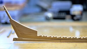
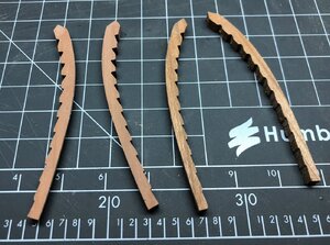
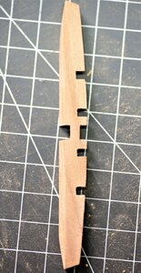
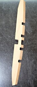
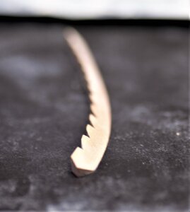
Shaping the stem and stern pieces. It is hard to explain, but I hope photos will explain themself.

600_0717.jpg

The process of shaping.

600_0706.jpg

600_0709.jpg

600_0710.jpg

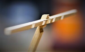
A bit blurry, but it shows the shape.

600_0717.jpg

Once both rising wood shaped, we will glue them to the kill. For proper positioning and aligning Trident provided templates Stern rising wood will be glued using the template CL53 (we originally use it when establishing bearding. line. For Stem rising wood we will use template CL52.

600_0737.jpg

600_0739.jpg

600_0741.jpg

600_0742.jpg

600_0744.jpg

600_0760.jpg

600_0761.jpg

600_0762.jpg

600_0763.jpg

600_0764.jpg

Thank you for the interest, sorry for the blurring photos, I am still learning photography. To be continued...
 
The book AOS (The Naval Cater Alert) shows the lower section of the stem and fore section of the keel (Part BL4) should be 'Boxing' together. However, in the kit version, this was simplified but fitted very well!
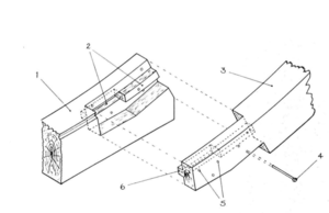
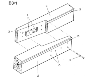
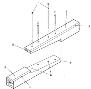
Perhaps the next challenge for the new generation of model ship kits companies like Trident and CAFModel is to delivery to its customers timber joinery like on the original ships.;)Screen Shot 2020-09-02 at 2.44.57 pm.pngScreen Shot 2020-09-02 at 2.51.55 pm.pngScreen Shot 2020-09-02 at 2.52.11 pm.png
 
Last edited:
Continue from the post #87

We are pretty much done with the entire keel assembly, we only left with two parts BL34 and BL33. Both parts are rising wood for the Stern and Stem. The trick is they have to be shaped firs before gluing on to the keel.

View attachment 176668

When removing those parts from fret, the greatest care should be taken to avoid 'nocking the top of the notches. The stern pieces were of good quality and required only shaping. One of the stem pieces was damaged by the CNC cutting tool (the first from the top).

View attachment 176670

I would try to fix it... but realized, it will require removing a lot of wood and would completely change the size. So... we all strive to be scratch modelers... right? I made one from scratch... Just to make sure they are identical I cut them together as a single piece. I glue (corners) of both pieces and transfer the shape. Notches lines were outlined using fine teeth saw and the rest cut with a hobby knife.

View attachment 176671

View attachment 176673

Here are both: the kit and scratch built from Pear.

View attachment 176672

Shaping the stem and stern pieces. It is hard to explain, but I hope photos will explain themself.

View attachment 176674

The process of shaping.

View attachment 176675

View attachment 176676

View attachment 176677

A bit blurry, but it shows the shape.

View attachment 176678

Once both rising wood shaped, we will glue them to the kill. For proper positioning and aligning Trident provided templates Stern rising wood will be glued using the template CL53 (we originally use it when establishing bearding. line. For Stem rising wood we will use template CL52.

View attachment 176679

View attachment 176680

View attachment 176681

View attachment 176682

View attachment 176683

View attachment 176684

View attachment 176685

View attachment 176686

View attachment 176687

View attachment 176688

Thank you for the interest, sorry for the blurring photos, I am still learning photography. To be continued...
Very good solution - well done my friend!
 
Jimsky, Oh wise and talented one, ;) ..I know this is your build log and I hope I'm not intruding...,BUT I seem to be having issues with marrying the stern keel and stern post to the cradle..and also with the Crosspiece B30.There seems to be a gap between the cradle and the stern post when everything on the keel has been lined up.
Did you or are you experiencing the same issue or is it my incompetence.Thanks for your forebearance. Cheers, Danielw
 
Greetings folks!! Hope all is well, and we will finish building the jig, The major work was already completed and photos of the process you've seen in the previous post.

Before I will post the final photos, I want to review and make my comments.
- Have a good sharp knife. I use the Olfa brand, with snap-off blades. This knife is really handy when you will cut small tabs holding the parts in the MDF boards. Some of the parts, the laser didn't cut thru. Cutting with a knife is a big challenge, I use my jewelers saw to cut out.
- One of my recommendations is to sand the end of the tabs before inserting them in the holes. This will give a good starting point. Before putting the glue - try a 'dry fit' first.
- I use Elmers's Wood glue max, I love this wood for MDF boards it is designed for incide\ouside use, which means it will adhere to climate influences. Any wood glue will do the job, just don't use CA
- Read the instruction, and don't skip the pages. Look a few steps ahead so you know what's next.

View attachment 174302

View attachment 174303

View from the top, without frames holder

View attachment 174304

View from the side

View attachment 174305

and top

View attachment 174306

Front view

View attachment 174307

View attachment 174308

View attachment 174309

Well...folks, this was fun and relatively quick. It is sturdy enough and ready to accept the keel! Did I say keel? We will build the keel next. Thank you for your interest and valuable comments. To be continued
sanding tabs-good . I think all the other tabs also need slight attention. The cut is too perfect, and too much "help" is needed . I only realised this by the 3rd diagram. With glue a little "ease" would be better . This MDF is only strong along the length but even then compresses easily. I'm no expert, but at this thickness, plywood wood be better. The thought going into planning this jig is amazing
 
Nice work, Jim! The kit seems very well designed. The CNC process makes assembly so much easier. Can you imagine removing laser char from all the notches in the keel and rising wood? For my money, CNC fabrication is really best. The negative is increased amount of wood needed to produce the kit.
 
Jimsky, Oh wise and talented one, ;) ..I know this is your build log and I hope I'm not intruding...,BUT I seem to be having issues with marrying the stern keel and stern post to the cradle..and also with the Crosspiece B30.There seems to be a gap between the cradle and the stern post when everything on the keel has been lined up.
Did you or are you experiencing the same issue or is it my incompetence.Thanks for your forebearance. Cheers, Danielw
Hello Dan! Thank you for the compliments!!! This build log is not just to show the build process and skills, it is to help others who might have questions when came across and stumble. There is no such thing as 'intruding' in my log. I am learning along with you, and if I can be on help, that would be the best honor for me! Please submit questions you may come across!! Please do so!!

Now, back to your question. Yes this part a bit tricky, First of all, use the self-adhesive template and affix to the part. one is going on one side, another the opposite side of BL30. You will have to grind (shape) both sides of the part shaded area.

600_0719.jpg

600_0720.jpg

Once you shape it, test the fit to the inner post (Part BL19), if necessary open a bit scarphs in the BL30 and BL19). This has to be done on a fit & try, as many times until it fits perfectly. Also, pay attention, the part BL30 has to angeled to the sternpost

600_0731.jpg
600_0722.jpg

600_0733.jpg

600_0734.jpg

600_0735.jpg

Pay attention for 4 notches, they should be facing the back.

600_0736.jpg

Let me know if this helps. ;)
 
Nice work, Jim! The kit seems very well designed. The CNC process makes assembly so much easier. Can you imagine removing laser char from all the notches in the keel and rising wood? For my money, CNC fabrication is really best. The negative is increased amount of wood needed to produce the kit.
[/QUO
Having just built the building jig, the amount of lasar char on the MDF was enormous. I needed to sand these . My hands were filthy black and needed washing every 10 mins. everything else in the area was smudged or dirty. ? small price to pay for accuracy.
 
Nice work, Jim! The kit seems very well designed. The CNC process makes assembly so much easier. Can you imagine removing laser char from all the notches in the keel and rising wood? For my money, CNC fabrication is really best. The negative is increased amount of wood needed to produce the kit.
Much appreciated, Dave. I totally agree with you! CNC is definitely the way to go, and I must admit, the CNC cut in this kit very accurate\pression with some small exceptions due to the wood grains. Also, it is a different experience working with CNC the edge is perfectly 90 degrees, wherein the laser cut is angeled. For POF - CNC is the way to go!!! :)
 
Back
Top