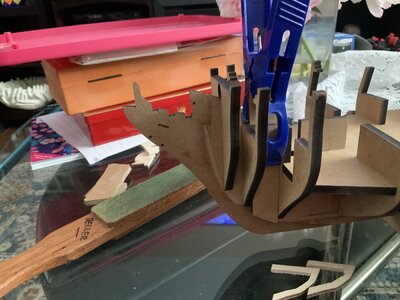
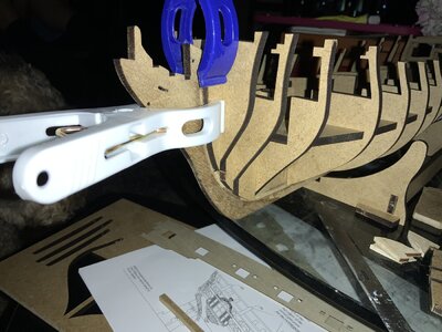
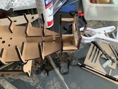
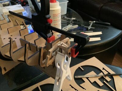
Oh Happy Day!!! I am finally starting to put in place the pieces to begin this adventure in ship building and honouring my family history. I have mentioned in other logs that I was planning on doing a build based on a family historical event. As most historical events passed on through the family, this one is a bit murky but there is enough information available that I can put together the pieces.
The family story is that following the 1st Scottish rebellion many Scotts were upset and looking to leave Scotland for greener pastures. Most booked passage and landed in many places around the world. One group of my clansmen happened upon a British 6th Rate ship that happened to be at anchor off the coast with a minimal crew aboard as the bulk of the troops were raiding the local population. The typical raping, pillaging and other soldiery shenanigans. This particular group of Scotts decided to kill the watch, take the ship and steal it. Oh, what a great idea! The stories that would be told of this great escapade. So they did take the ship and cast off before the rest of the crew made it back. Ha Ha Ha, what a caper!!!
  The ship was found 2 weeks later adrift in the mid Atlantic as none of these brilliant ancestors of mine had any idea of how to sail.
  The ship was retaken, most of my clansmen were sent back to the UK as prisoners and later hung.
  The leaders of the clan were minor Scottish Nobels and so were sent to Jamaica to be dealt with. Luckily enough for my ancestors the Governor of Jamaica was a distant relative and so they were released. This was the beginning of the Edgar clan plantation in Trelawny, Jamaica established by Alexander Edgar in 1720.
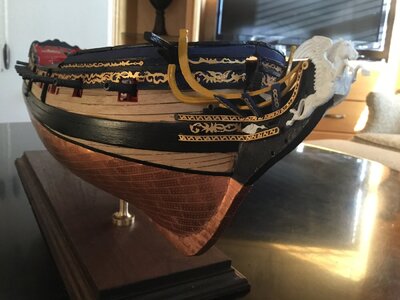
So based on this family story I wanted to build a typical British 6th rate coastal ship that would have been used during that time. Even though the HMS Fly was not built until the late 18th century the style of ship is similar as to what was captured by my infamous ancestor.
Here is a reference from the Admiralty logs.
Joseph Griffin, Clerk of the Cheque, Kinsale. The Enterprise, Captain Mungo Herdman, has arrived from Cork with transports carrying soldiers and the Lively, Captain John Carleton, has brought some Scottish prisoners captured by the privateer the John of Jamaica, Thomas Blake, Master.
1719 Aug 23
So I am planning on recreating the moment of celebration as the great caper was completed and the ship then sailed off into the sunset...
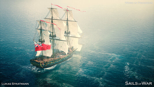
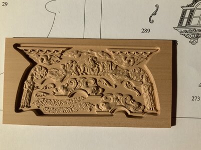
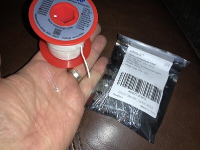
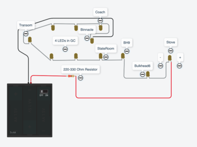
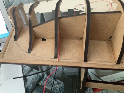
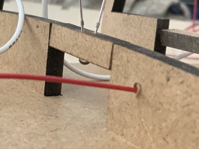
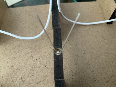
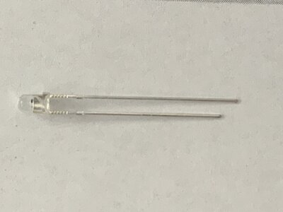
I have purchased the upgrade to the Fly, a carving from Russia for the Fly as well as several boxes of sailors, Scotts and British miniatures to bash my diorama. I am also planning on doing a bit of a bash on the kit as I want to create the Captain's cabin with actual windows that can be seen through into the cabin. I will also be creating lighting inside the build using flickering yellow LED lights to simulate candles and lanterns. I will also be adding some additional components, like the galley stove under the forward deck and some other internal features on the lower decks. I'm also going to try and figure out a way to make the transom windows removable for a full interior view of the Captain's cabin. Maybe a hinge or something along those lines.
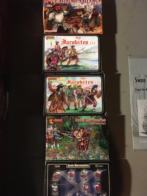
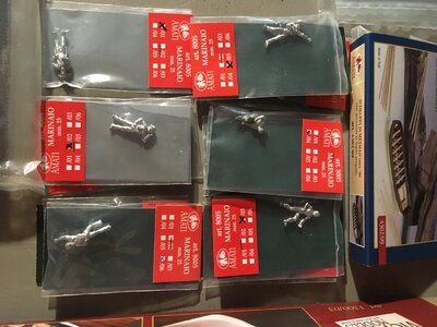
Here are the figures I purchased to populate the ship. I just need to add a set of British naval troops to the set. They'll all be dead of course but I think a few dangling from the rigging or laying on the deck would be appropriate.
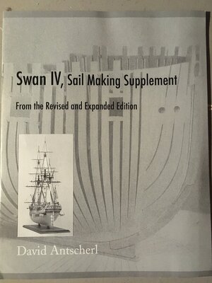
I have purchased the David Antscherl book on the Pegasus build (same as Fly) as well as the supplement for rigging and sails for Swan Class ships.
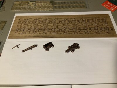
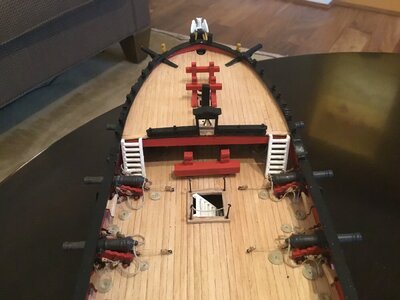
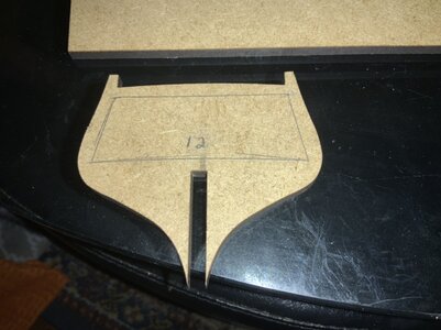
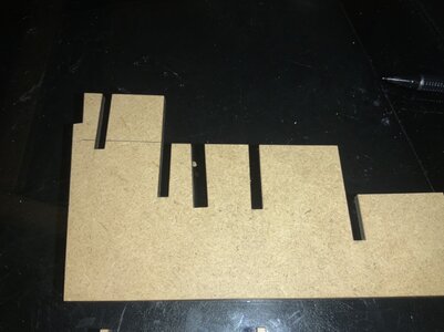
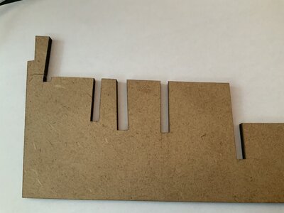
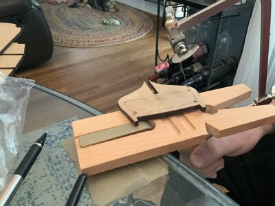
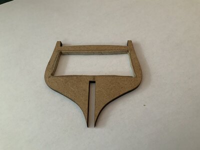
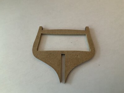
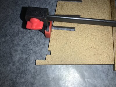
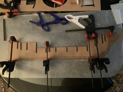
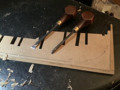
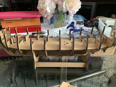
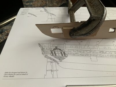
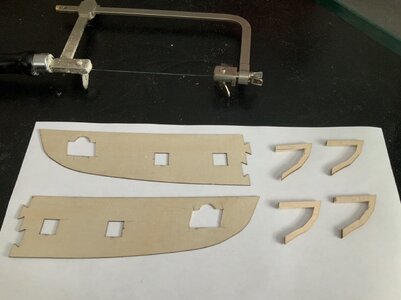
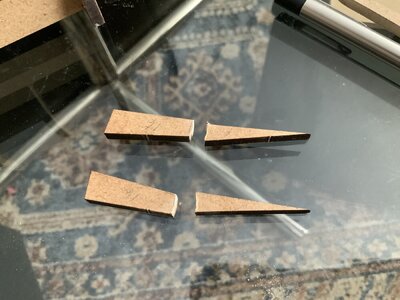
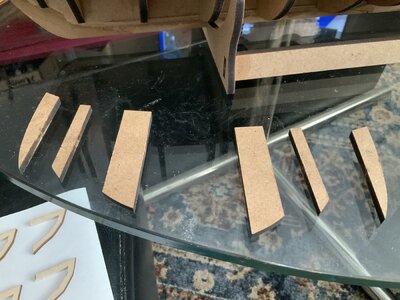
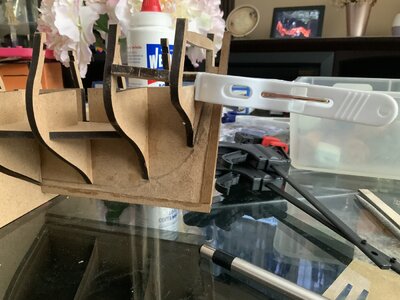
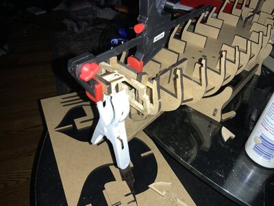
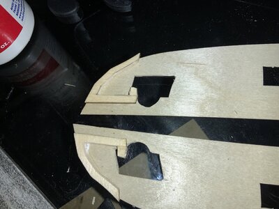
The actual kit opening I will skip, as that is in many build logs but here are the pics of the kit and pieces.
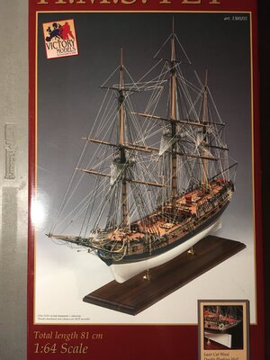
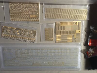
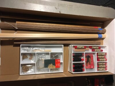
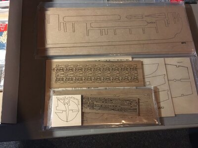
I will be beginning the keel soon and going back and forth between completing my Bluenose and this build.
I apologize in advance for all the mistakes I'm going to make, the too many questions I will be asking and the artistic license in my bashing and creating of this pseudo historical diorama of crazy Scotts. I'm sure much drinking was involved in the decision making process.


The family story is that following the 1st Scottish rebellion many Scotts were upset and looking to leave Scotland for greener pastures. Most booked passage and landed in many places around the world. One group of my clansmen happened upon a British 6th Rate ship that happened to be at anchor off the coast with a minimal crew aboard as the bulk of the troops were raiding the local population. The typical raping, pillaging and other soldiery shenanigans. This particular group of Scotts decided to kill the watch, take the ship and steal it. Oh, what a great idea!
 The ship was found 2 weeks later adrift in the mid Atlantic as none of these brilliant ancestors of mine had any idea of how to sail.
  The leaders of the clan were minor Scottish Nobels and so were sent to Jamaica to be dealt with. Luckily enough for my ancestors the Governor of Jamaica was a distant relative and so they were released. This was the beginning of the Edgar clan plantation in Trelawny, Jamaica established by Alexander Edgar in 1720.
So based on this family story I wanted to build a typical British 6th rate coastal ship that would have been used during that time. Even though the HMS Fly was not built until the late 18th century the style of ship is similar as to what was captured by my infamous ancestor.
Here is a reference from the Admiralty logs.
Joseph Griffin, Clerk of the Cheque, Kinsale. The Enterprise, Captain Mungo Herdman, has arrived from Cork with transports carrying soldiers and the Lively, Captain John Carleton, has brought some Scottish prisoners captured by the privateer the John of Jamaica, Thomas Blake, Master.
1719 Aug 23
So I am planning on recreating the moment of celebration as the great caper was completed and the ship then sailed off into the sunset...

I have purchased the upgrade to the Fly, a carving from Russia for the Fly as well as several boxes of sailors, Scotts and British miniatures to bash my diorama. I am also planning on doing a bit of a bash on the kit as I want to create the Captain's cabin with actual windows that can be seen through into the cabin. I will also be creating lighting inside the build using flickering yellow LED lights to simulate candles and lanterns. I will also be adding some additional components, like the galley stove under the forward deck and some other internal features on the lower decks. I'm also going to try and figure out a way to make the transom windows removable for a full interior view of the Captain's cabin. Maybe a hinge or something along those lines.
Here are the figures I purchased to populate the ship. I just need to add a set of British naval troops to the set. They'll all be dead of course but I think a few dangling from the rigging or laying on the deck would be appropriate.


I have purchased the David Antscherl book on the Pegasus build (same as Fly) as well as the supplement for rigging and sails for Swan Class ships.

The actual kit opening I will skip, as that is in many build logs but here are the pics of the kit and pieces.


I will be beginning the keel soon and going back and forth between completing my Bluenose and this build.
I apologize in advance for all the mistakes I'm going to make, the too many questions I will be asking and the artistic license in my bashing and creating of this pseudo historical diorama of crazy Scotts. I'm sure much drinking was involved in the decision making process.


