Victory Models HMS Fly 1/64 Diorama by TechTrek

Love the way you explain the level of details. This for sure will help others. Many thanks, Chris. Thumbs-Up
 
In order for the leds to flicker randomly, they must be wired in parallel, not series. In series, when one lamp flickers, it cuts off the power to the remainder so they all go on and off together. Ask me how I know.
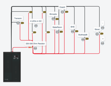
I will create a test circuit, thanks for letting me know.
 
Thanks @Nigeld for the warning. I created a test circuit and low and behold the parallel circuit works fine but the series circuit does not even come on, I'm guessing I'm trying to get too much out of the line with multiple lights. I shot 2 very short videos of the circuit with both series and parallel together and another with all parallel. Here is the updated circuit diagram.
Screen Shot 2021-01-21 at 2.26.38 PM.png
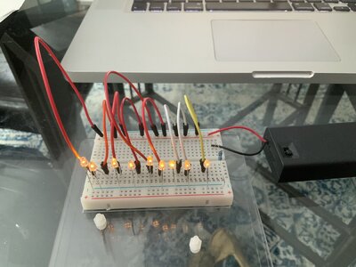
Unfortunately the video is in .MOV format and not compatible. So you can't see the pretty lights flashing. Here's a pic of the circuit running on a breadboard.

Circuit.jpg
 
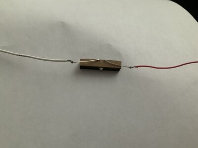
Lesson number 2, wiring an LED light. This method of wiring the connection works for pretty much any type of wire, stranded or solid core.
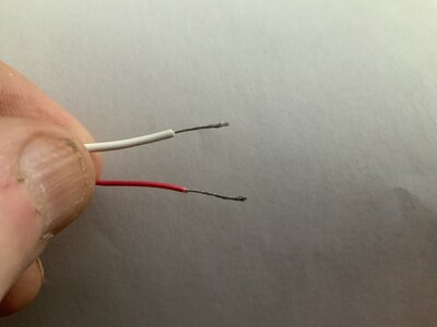
1 - strip 1 - 2 cm of plastic shielding from the wire exposing the copper or other metal centre. If the wire is in strands, like pieces of hair, twirl them together into a solid bunch.
C51DF221-4E12-4974-86CE-D63E23B95097.jpeg
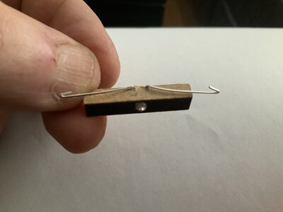
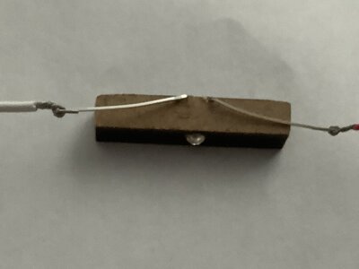
2 - bend your wires to be connected back on itself to make a hook on each end of the wires.
AD5009D7-8E20-41FE-A4C1-519C90B4F21C.jpeg20C68EE7-CF18-4217-ADC6-71F5E771DB94.jpeg
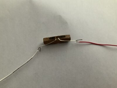
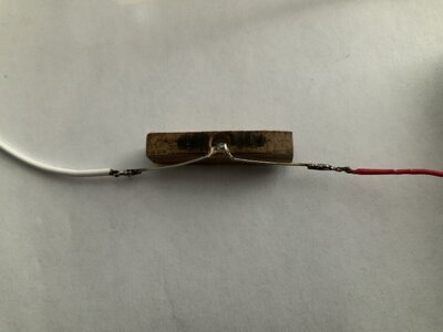
3 - twist the wire around itself so it’s tight to the other wire. If these were two wires you would just twist them. In this case there is the solid LED leg that does not twist around itself. Use a pair of pliers to tighten the bend.
C41EF19B-53DD-4D3B-BABC-19EA15D95DB5.jpeg6A381BC1-AA78-4E32-B8CA-D9E854F7C854.jpeg
4 - at this point the connection is nice and solid. I recommend soldering the connection but it will hold as is.
D6B68E7D-E255-4D79-A99E-0343B594DB43.jpeg
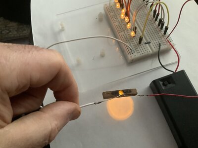
5 - final step is to test your connection before you bury it in your model.
3FA4A072-9394-40E1-A4D0-E05445BA5E30.jpeg
6 - now you can install the light into your model. Thumbsup ;)
image.jpg
To prevent the exposed wires from shorting out from touching something they shouldn’t a hot glue gun makes an awesome insulator, holds the wires in place and prevents them from pulling apart.
BeerBeerBeerCheers and happy wiring.
 
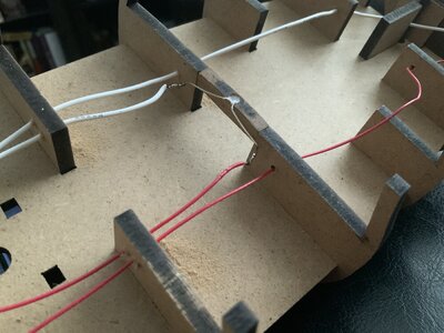
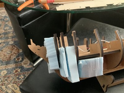
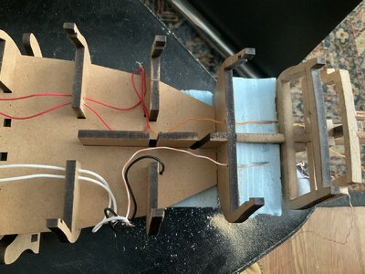
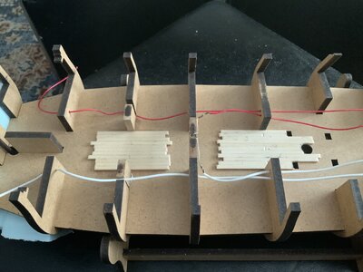
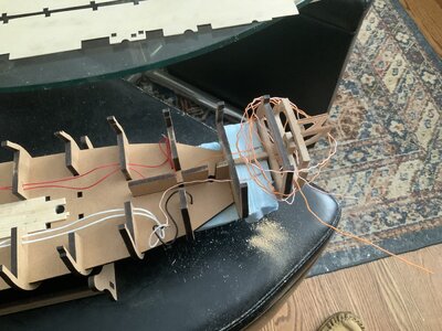
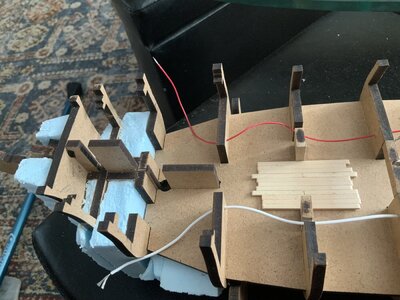
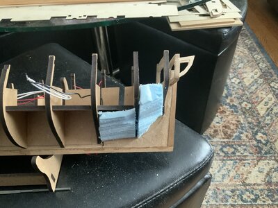
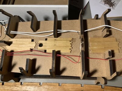
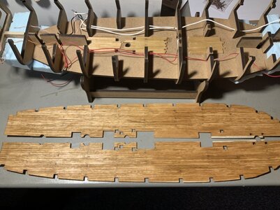
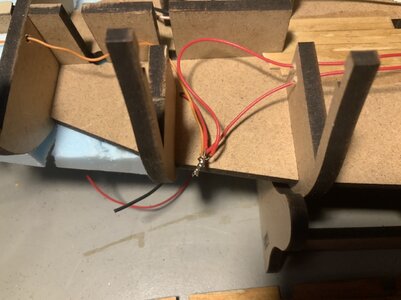
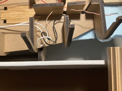
Day 3, I think? A few things done now, planks laid in the lower deck below the fore and main hatches. Blue insulation material I had laying around glued between bulkheads fore and aft. Wiring connected below deck with (+) and (-) run into the stern for upper deck wiring. All my LEDs are going to be connected with (+) leg running on the starboard side and (-) on the port side. I’ve left lots of wire wrapped around the stern. The orange wire will always carry (+) and the white/orange striped wire will carry (-). Here’s some hopefully self explanatory pics.
05FA7B20-4DFD-48C8-9DDE-51F392538AD1.jpeg51CCF5D3-69DC-440C-ABE6-E71ACF0EFD03.jpeg5364E26E-388A-4670-B639-BDC82365E8EF.jpeg0FFD0FF1-1228-4757-A6C1-22198D6BCF7D.jpeg9EFEF8CA-992A-4050-B8DB-ADE8B082F996.jpeg9E1507C7-25FC-4428-8A85-E41E1C39EAD4.jpeg
 
Day 4 progress...
The lower deck has been planked in all the areas that could be seen through a hatch. Treenails method tested on lower planks and stain applied.
4786C2C1-9600-40BB-8B05-2CD577422101.jpeg
Main deck planked, nail holes done and stain applied.
125387CF-BE62-4186-A15D-679D6FA43624.jpeg
The main under deck wiring has been soldered.
2148F762-3D93-4621-8FCB-4A15635A875B.jpeg256DB61E-55F7-4E61-8D4B-FC482BD453D0.jpegAlmost ready to glue down the main deck. Will do another dry fit and drill holes for wiring through the deck where the galley stove will be installed. I’m hoping the flickering LED will adequately simulate the fire in the stove.
 
I started to put the transom pieces in place and the outside supports need to be angled with the side pieces that contain the cabin windows and gun ports. So I rethought the process and decided to glue the pieces directly onto the side pieces, when the sides get glued on the angle will be perfect. The small support pieces between the forward bulkheads were glued in place. Part 16 had to be cut down due to the bashed cabin, both pieces. I’ll need to figure out what I’m going to do with the internal structure behind the cabin side windows. I may need to cut some of it away after the sides are installed.
View attachment 207236View attachment 207244View attachment 207238View attachment 207240View attachment 207243View attachment 207239View attachment 207241View attachment 207242View attachment 207245
A very tidy bit of construction Chris!
 
Looking good Chris. I can give you some explanation about the wiring of the led's. The main différance between parallel and series circuit. is as follows. In a parallel circuit The current is divided up and the voltage stays the same for all the led's In a series circuit the voltage is divided up and the current stays the same. So if you have 6 led's in series and a 6 volt supply you would only have 1 volt for each led.
 
Looking good Chris. I can give you some explanation about the wiring of the led's. The main différance between parallel and series circuit. is as follows. In a parallel circuit The current is divided up and the voltage stays the same for all the led's In a series circuit the voltage is divided up and the current stays the same. So if you have 6 led's in series and a 6 volt supply you would only have 1 volt for each led.
Thanks for the explanation.
 
Thanks for the explanation.
Currents and Volts. . . I get confused enough trying to use the right glue for parts that I may have to later disassemble by some "solvent" to start over again and not mess it up again. The added feature of LED lighting and wiring is above my level. Nice opportunity though for your finished ship. :) Are the sails proving solar power? :cool: No disrespect . . . just admiration for your direction. Rich (PT-2)
 
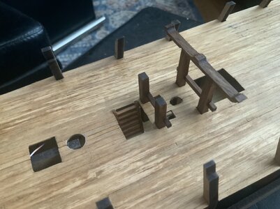
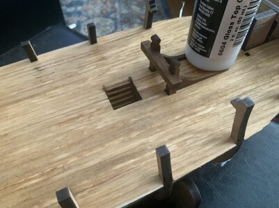
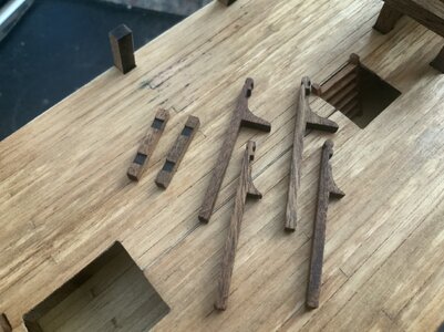
Progress on deck pieces. I like the walnut so I’m leaving it natural with a light stain and then a clear topcoat sealer. Ladders below deck are done and glued in. Now for the creation of the stove, not a Brodie as this was built prior to that. I will also start working on the aft cabins, furniture and other detail pieces.
35A10C6E-4D75-416B-BED8-FF5A49914C7B.jpeg7094A3FD-1F4A-4C79-B2BD-C9B9FF9727E4.jpegDD6B5FEB-5FE4-4511-97AB-1B62FCDD3231.jpeg
 
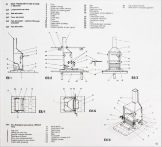
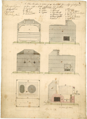
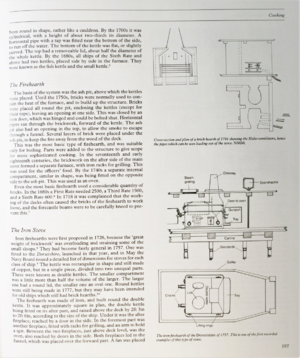
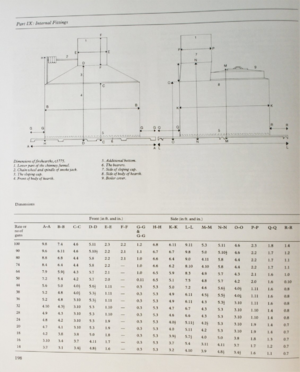
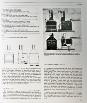
Here are some various stove / fire-hearth plans I will be using to create my stove. Not sure which version would have gone on the HMS Fly as both have the correct footprint and chimney location and style. I’m leaning towards the 1st one as it is smaller and the Fly’s crew complement is 125, the 2nd style is for a larger crew (250).
879C278C-987A-424D-8F3E-DF6CA2778F8B.png2796753A-C467-44D1-B202-E5D179DD919E.png5C428EAE-2F57-496D-84BE-2D0BD183458A.png02958955-D255-4E3B-92F2-6E84283B30AF.png541323A3-465E-46FF-B511-CFFADAFE6B5E.png
 
Here are some various stove / fire-hearth plans I will be using to create my stove. Not sure which version would have gone on the HMS Fly as both have the correct footprint and chimney location and style. I’m leaning towards the 1st one as it is smaller and the Fly’s crew complement is 125, the 2nd style is for a larger crew (250).
View attachment 208762View attachment 208763View attachment 208764View attachment 208765View attachment 208766
Good luck! I love your ambition! To be rendered in metal?
 
Last edited:
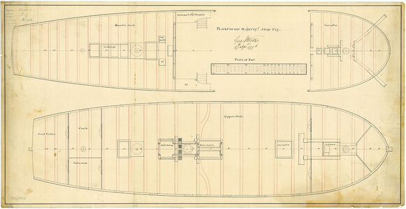
So here is the pic of the Fly original plans, the hearth looks more like a Brodie footprint but that wasn’t invented until a few years later??? This stove, listed as a fireplace, has the chimney towards aft and the bulk of the stove almost up against the foremast. There is about 1 foot of space between the mast and the forward edge of the stove. Perhaps this is the footprint of the bricks below the 1st stove and the cook would stand on the bricks or off to the side while cooking. The wood or coal is loaded from the side, same with the oven access. The rotisserie handle is also from the side and there is a grating above this area, so perhaps I've rambled into my own answer. Any advice or suggestions would be happily accepted.
FLY 1776 j7976.jpg
 
Back
Top