Introduction.
I have read various SOS postings on the merits of various Vasa kits: Billing, Corel, d'Agostini, Mantua.
I have settled on the Corel version even though it is not the most highly favoured.
The kit is about half the price of d'Agostini and the negative comparisons (accuracy etc.) are not issues that I am too bothered about.
It is unlikely that I will visit the Stockholm Museum with my model under my arm and feel mortified by discrepencies.
Aside. Many 'classic' ship models (eg Golden Hind, Revenge, Santa Maria, Mayflower) are based on conjecture but we accept the inherent inaccuracy.
Old ships for which the original exists are few. Victory, Cutty Sark, Vasa, bits of Mary Rose are some exceptions .
I am content for my Vasa model to be somewhere between these categories.
The 1:75 scale is more appealing than 1:60 - I am fast running out of display sites and I don't think SWMBO would take kindly to having her books jettisoned.
I will post some pictures of the box contents later. For the moment I will comment on the paperwork.
There are several large sheets of detailed, helpful-looking assembly diagrams. The instructions are not quite so good.
The 'Official' looking leaflet (stapled and folded as a booklet) is in Italian. Fair enough for an Italian kit.
This is supplemented by loose leaf sheets of photocopied translations of instructions in English, French and German.
The accompanying parts lists remain in Italian - apart from the German version which has been translated
With the aid of Google Translate I shall soon become trilingual in the names of ship parts and the types of wood.
Prua = bow; poppa = stern; buche = beech etc.
Had this been the subject of school French lessons (rather than what Jean has for breakfast) I might have been more intrersted.
The kit
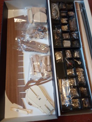
The kit comes in a good, stout, cardboard box. There are two plastic trays divided into compartments.
One primarily contains rigging componrents: blocks, dead-eyes, cord and sundry other small items.
The other contains the decorative bits. Both can be put aside unopened for a while.
A long, removable inner box (useful) contains the planking and dowels nicely bundled.
Remaining parts are grouped into plastic bags. apart from the keel and bulkheads ( =ordinata or spants) most components seem to be
cut from solid, rather than plywood.
I like the fact that all the sheet components have been fully cut and (where viable) stamped with numbers.
Other kits I have made (OcCre, Caldercraft) retained all components within a sheet by leaving small, uncut segments. (sprues?)
I found cutting hundreds of these and smoothing off the residual stumps very tedious.
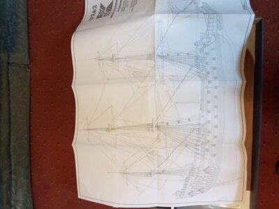
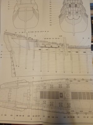
I have photographed a couple of the instruction sheets to give a flavour of their quality.
They are very large (!) and very clear. There are twelve in all.
Time to start building.
The Frame
In previous builds the assembly of bulkheads and keel has taken only a few minutes after extracting the components from a cut sheet
and trimming off the blips.
Not so with this kit! All the slots in the bulwarks were too narrow to accommodate the keel; most of the slots in the keel
were too narrow to accommodate the bulkheads. It took hours with blade and file to make them wider.
There are slits in the edges of the bulkheads to act as guides for the first layer of planking. The first picture below shows the results
of an initial, dry assembly with a thin strip of material temporarily inserted into one row of slits.
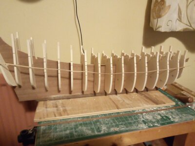
Rather than forming a smooth curve, the inserted strip was very wavy: it looked like the design of a roller coaster for the timid.
The depth of selected bulkhead slots were extended to improve the algnment. After further work with file and chisel to modify the
channels for the longerons I finally manged to get a reasonable assembly with a few small compromises on the vertical displacements.
The main deck (after widening a few edge slots too narrow to take a bulkhead) seem to touch (or almost touch) most of the bulkhead tops.
The following photo shows the glued up assembly.
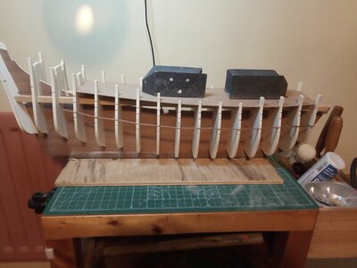
I'm not sure what the longerons are for. Given that the bulkeads are held square to the keel by the slots alnog
the edges of the deck the logerons don't seem to add anything. Perhaps I shall find their function later.
I hope the remaining thousands of components fit together more easily! Perhaps laser cutting has its merits.
Bow blocks
This kit uses bow blocks to fill the quadrants between the keel and the first bulkhead.
The intention seems to be that these will be covered by both layers of planking.
However, if the bow blocks are extended 1.5mm beyond the bulkhead then the first layer of planking could be stopped there.
This would save tapering, soaking, bending and retaining the first layer planks round a fairly tight curve.
The forward edge of the blocks where they meet the stem would also need extending.
Unfortunately, the bow blocks provided in the kit are not quite big enought to deploy this idea.
I have therefore packed them out with offcuts of plywood: one cut to the profile of the chamfered first bulkhead (+1.5mm)
and one to the profile where the planks would have met the keel (+1.5mm)
The extended, raw bow blocks were then carved to the final shape of the bow.
In this process the plywood attachments served as a useful guide when removing waste wood.
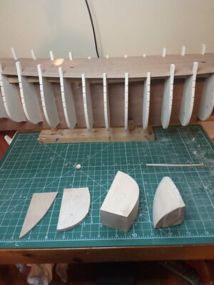
The following photo shows the two plywood profiles and the raw bow block from the kit for the port
side yet to be processed. Also, the completed starboard bow block.
I must take care to assemble the second bow block as a PORT version!
When the first layer of planks is installed the interface of the plank ends with the bow blocks can be smoothed
as necessary. Final shaping of the bow blocks can be done if indicated by dry fitting of some scond layer planks.
Aside: Is it just me or something about this site that enhances the number of typographical errors I make?
Deck fittings
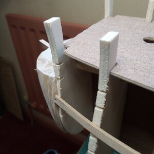
I have fitted the extended bow blocks. The second picture above has a first layer plank temporarily pinned in place to illustrate
the intention of the extension. The intersection will be smothed when the first layer planks are finally placed.
The Corel instructions emphasise that the components of the kit should be fitted in numerical order. The next items listed are various deck items.
These precede both the deck planking and hull planking which seems a bit odd but I will do as instructed.
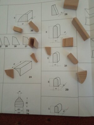
At this point the man who stamped useful numbers on the keel, decks and bulkhead components appears to have run out of ink.
The next items need to be identified from an instruction sheet. I have sprinkled a few at random on said heet pictured below.
Cladding
The build requires most deck structures and exposed bulkheads to be clad with 2 x 3 mm walnut strips.
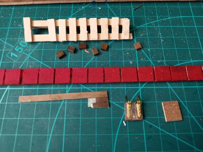
Hundreds are needed; some as short as 6mm. After cutting and applying a few individually it became clear
that this would be a task to rival ratlining in a tedium contest. I have adopted the following shortcut.
A number of walnut strips (currently 8) are laid together on a strip of masking tape. Eight pieces of identical length
can then be made in a single sawcut. The eight pieces, still attached to the tape, can be glued in place.
When the glue has set the tape can be removed. A few individual pieces need to be processed on the tighter curves.
The following photo shows a variety of pieces at various stages of the process.
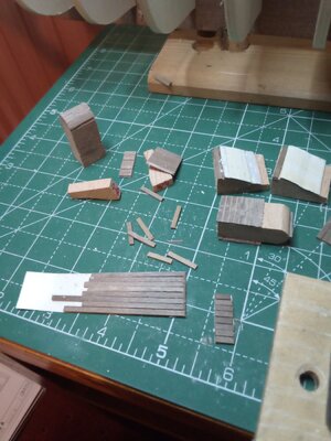
The bottom left item is the remaing part of an original 20cm set of 8 strips from which cladding pieces have been cut.
I might consider a variation on this process later on when the decks are being planked.
First stage planking.
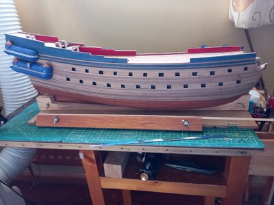
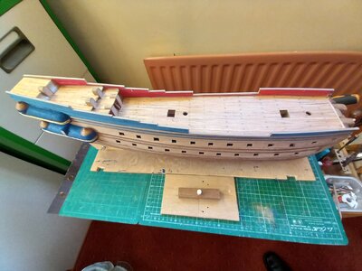
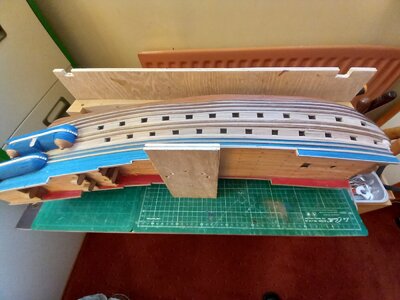
This is partially complete. The picture below shows my crude method of holding newly added planks with thin strips of plywood screwed at the top and pegged at the bottom. When the time comes I guess they can be turned upwards to assist planking the gunwales
The pegging is made more complicated because the pre-cut bulwarks were not from the same sheet of ply: some are 5mm thick; some 5.5mm.
The protusions at bow and stern pass right though the hull and provide 'legs' which, combined with the keel stand, provide a stable support for the model when lying on its side but clear of the bench. With a suitable cradle (yet to be made) they will support the model when inverted. They will be removed when planking is complete and the gaps they leave made good.
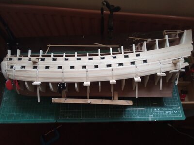
First stage planking continued.
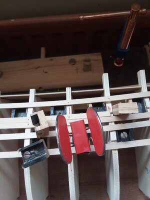
The Corel instructions say to start the planking with two pairs of planks placed just above and below the two rows of gun ports. Notches on the bulkheads mark the positions. Blocks that will later receive the dummy gun barrels are placed behind these initial planks. The instructions refer to these as a 'new patented system' which seems to be nothing more then a length of wood with a channel ploughed out of it. See illustration later. These wold be drilled later to receive the dummy barrels but I was not impressed by the amount of glued contact between the blocks and planks so I drilled them before fitting. If they should become detached while drilling later in the build it would be nigh impossible to retrieve them.
Placing and retaining these blocks while the glue set was fiddly - especially reaching up behind the lower planks to upper row of gun ports. I resolved this by insering a screw (finger tight) into the drilled holes. This had the added advantage of identifying the position and angle that the gun barrels would later take. The picture below shows various aspects of this process.
When doing the other side I simplified the process by completing the upper row of gun ports before applying planks and blocks for the lower.
When completing the planking for the port side I measured round the curve of the largest ("hals"?) bulhead to be 21 plank widths. Measuring at other points (particularly the stem and transom) established a profile to taper the planks so that all would reach the keel simultaneously. This was not a great idea: the planks required forcing into progressively upward sweeps as the stern was approached.
For the starboardt side I tapered the bow end of the planks but left the aft end untapered. The planks attached to the transom met the keel with four still required further forward. The last four planks were tapered to points at their aft ends.
This appeared to be the better and quicker option. This lesson might be of value when planning the strategy for the scond layer planking.
I found that the accuracy to which the bulkheads were cut leaves much to be desired. Occasional ones were a bit 'small'. Forcing the planks to contact them would create shallow depressions in the profile. I compromised by allowing the planks to float across the offending bulkeads. I did not spot this in the dry fit of keel and bulkheads but if I had I doubt I wuld have tried to reshape the majority to conform with the rogues. Perhaps laser cut cut sheets are worth the extra effort of trimming off the sprues.
I have read various SOS postings on the merits of various Vasa kits: Billing, Corel, d'Agostini, Mantua.
I have settled on the Corel version even though it is not the most highly favoured.
The kit is about half the price of d'Agostini and the negative comparisons (accuracy etc.) are not issues that I am too bothered about.
It is unlikely that I will visit the Stockholm Museum with my model under my arm and feel mortified by discrepencies.
Aside. Many 'classic' ship models (eg Golden Hind, Revenge, Santa Maria, Mayflower) are based on conjecture but we accept the inherent inaccuracy.
Old ships for which the original exists are few. Victory, Cutty Sark, Vasa, bits of Mary Rose are some exceptions .
I am content for my Vasa model to be somewhere between these categories.
The 1:75 scale is more appealing than 1:60 - I am fast running out of display sites and I don't think SWMBO would take kindly to having her books jettisoned.
I will post some pictures of the box contents later. For the moment I will comment on the paperwork.
There are several large sheets of detailed, helpful-looking assembly diagrams. The instructions are not quite so good.
The 'Official' looking leaflet (stapled and folded as a booklet) is in Italian. Fair enough for an Italian kit.
This is supplemented by loose leaf sheets of photocopied translations of instructions in English, French and German.
The accompanying parts lists remain in Italian - apart from the German version which has been translated
With the aid of Google Translate I shall soon become trilingual in the names of ship parts and the types of wood.
Prua = bow; poppa = stern; buche = beech etc.
Had this been the subject of school French lessons (rather than what Jean has for breakfast) I might have been more intrersted.
The kit


The kit comes in a good, stout, cardboard box. There are two plastic trays divided into compartments.
One primarily contains rigging componrents: blocks, dead-eyes, cord and sundry other small items.
The other contains the decorative bits. Both can be put aside unopened for a while.
A long, removable inner box (useful) contains the planking and dowels nicely bundled.
Remaining parts are grouped into plastic bags. apart from the keel and bulkheads ( =ordinata or spants) most components seem to be
cut from solid, rather than plywood.
I like the fact that all the sheet components have been fully cut and (where viable) stamped with numbers.
Other kits I have made (OcCre, Caldercraft) retained all components within a sheet by leaving small, uncut segments. (sprues?)
I found cutting hundreds of these and smoothing off the residual stumps very tedious.
I have photographed a couple of the instruction sheets to give a flavour of their quality.
They are very large (!) and very clear. There are twelve in all.
Time to start building.
The Frame
In previous builds the assembly of bulkheads and keel has taken only a few minutes after extracting the components from a cut sheet
and trimming off the blips.
Not so with this kit! All the slots in the bulwarks were too narrow to accommodate the keel; most of the slots in the keel
were too narrow to accommodate the bulkheads. It took hours with blade and file to make them wider.
There are slits in the edges of the bulkheads to act as guides for the first layer of planking. The first picture below shows the results
of an initial, dry assembly with a thin strip of material temporarily inserted into one row of slits.

Rather than forming a smooth curve, the inserted strip was very wavy: it looked like the design of a roller coaster for the timid.
The depth of selected bulkhead slots were extended to improve the algnment. After further work with file and chisel to modify the
channels for the longerons I finally manged to get a reasonable assembly with a few small compromises on the vertical displacements.
The main deck (after widening a few edge slots too narrow to take a bulkhead) seem to touch (or almost touch) most of the bulkhead tops.
The following photo shows the glued up assembly.

I'm not sure what the longerons are for. Given that the bulkeads are held square to the keel by the slots alnog
the edges of the deck the logerons don't seem to add anything. Perhaps I shall find their function later.
I hope the remaining thousands of components fit together more easily! Perhaps laser cutting has its merits.
Bow blocks
This kit uses bow blocks to fill the quadrants between the keel and the first bulkhead.
The intention seems to be that these will be covered by both layers of planking.
However, if the bow blocks are extended 1.5mm beyond the bulkhead then the first layer of planking could be stopped there.
This would save tapering, soaking, bending and retaining the first layer planks round a fairly tight curve.
The forward edge of the blocks where they meet the stem would also need extending.
Unfortunately, the bow blocks provided in the kit are not quite big enought to deploy this idea.
I have therefore packed them out with offcuts of plywood: one cut to the profile of the chamfered first bulkhead (+1.5mm)
and one to the profile where the planks would have met the keel (+1.5mm)
The extended, raw bow blocks were then carved to the final shape of the bow.
In this process the plywood attachments served as a useful guide when removing waste wood.
The following photo shows the two plywood profiles and the raw bow block from the kit for the port
side yet to be processed. Also, the completed starboard bow block.
I must take care to assemble the second bow block as a PORT version!
When the first layer of planks is installed the interface of the plank ends with the bow blocks can be smoothed
as necessary. Final shaping of the bow blocks can be done if indicated by dry fitting of some scond layer planks.
Aside: Is it just me or something about this site that enhances the number of typographical errors I make?


Deck fittings
I have fitted the extended bow blocks. The second picture above has a first layer plank temporarily pinned in place to illustrate
the intention of the extension. The intersection will be smothed when the first layer planks are finally placed.
The Corel instructions emphasise that the components of the kit should be fitted in numerical order. The next items listed are various deck items.
These precede both the deck planking and hull planking which seems a bit odd but I will do as instructed.
At this point the man who stamped useful numbers on the keel, decks and bulkhead components appears to have run out of ink.
The next items need to be identified from an instruction sheet. I have sprinkled a few at random on said heet pictured below.

Cladding
The build requires most deck structures and exposed bulkheads to be clad with 2 x 3 mm walnut strips.
Hundreds are needed; some as short as 6mm. After cutting and applying a few individually it became clear
that this would be a task to rival ratlining in a tedium contest. I have adopted the following shortcut.
A number of walnut strips (currently 8) are laid together on a strip of masking tape. Eight pieces of identical length
can then be made in a single sawcut. The eight pieces, still attached to the tape, can be glued in place.
When the glue has set the tape can be removed. A few individual pieces need to be processed on the tighter curves.
The following photo shows a variety of pieces at various stages of the process.

The bottom left item is the remaing part of an original 20cm set of 8 strips from which cladding pieces have been cut.
I might consider a variation on this process later on when the decks are being planked.
First stage planking.
This is partially complete. The picture below shows my crude method of holding newly added planks with thin strips of plywood screwed at the top and pegged at the bottom. When the time comes I guess they can be turned upwards to assist planking the gunwales
The pegging is made more complicated because the pre-cut bulwarks were not from the same sheet of ply: some are 5mm thick; some 5.5mm.
The protusions at bow and stern pass right though the hull and provide 'legs' which, combined with the keel stand, provide a stable support for the model when lying on its side but clear of the bench. With a suitable cradle (yet to be made) they will support the model when inverted. They will be removed when planking is complete and the gaps they leave made good.

First stage planking continued.
The Corel instructions say to start the planking with two pairs of planks placed just above and below the two rows of gun ports. Notches on the bulkheads mark the positions. Blocks that will later receive the dummy gun barrels are placed behind these initial planks. The instructions refer to these as a 'new patented system' which seems to be nothing more then a length of wood with a channel ploughed out of it. See illustration later. These wold be drilled later to receive the dummy barrels but I was not impressed by the amount of glued contact between the blocks and planks so I drilled them before fitting. If they should become detached while drilling later in the build it would be nigh impossible to retrieve them.
Placing and retaining these blocks while the glue set was fiddly - especially reaching up behind the lower planks to upper row of gun ports. I resolved this by insering a screw (finger tight) into the drilled holes. This had the added advantage of identifying the position and angle that the gun barrels would later take. The picture below shows various aspects of this process.
When doing the other side I simplified the process by completing the upper row of gun ports before applying planks and blocks for the lower.

When completing the planking for the port side I measured round the curve of the largest ("hals"?) bulhead to be 21 plank widths. Measuring at other points (particularly the stem and transom) established a profile to taper the planks so that all would reach the keel simultaneously. This was not a great idea: the planks required forcing into progressively upward sweeps as the stern was approached.
For the starboardt side I tapered the bow end of the planks but left the aft end untapered. The planks attached to the transom met the keel with four still required further forward. The last four planks were tapered to points at their aft ends.
This appeared to be the better and quicker option. This lesson might be of value when planning the strategy for the scond layer planking.
I found that the accuracy to which the bulkheads were cut leaves much to be desired. Occasional ones were a bit 'small'. Forcing the planks to contact them would create shallow depressions in the profile. I compromised by allowing the planks to float across the offending bulkeads. I did not spot this in the dry fit of keel and bulkheads but if I had I doubt I wuld have tried to reshape the majority to conform with the rogues. Perhaps laser cut cut sheets are worth the extra effort of trimming off the sprues.
Last edited:


