
-

SUBSCRIBE TO SHIPS IN SCALE TODAY!
The beloved Ships in Scale Magazine is back and charting a new course for 2026!
Discover new skills, new techniques, and new inspirations in every issue.
NOTE THAT OUR NEXT ISSUE WILL BE July/August 2026 -

Win a Free Custom Engraved Brass Coin!!!
As a way to introduce our brass coins to the community, we will raffle off a free coin during the month of August. Follow link ABOVE for instructions for entering.
- Home
- Forums
- Ships of Scale Group Builds and Projects
- HMS Alert 1777 1:48 PoF Group Build
- HMS Alert 1777 1:48 Group Build Logs
You are using an out of date browser. It may not display this or other websites correctly.
You should upgrade or use an alternative browser.
You should upgrade or use an alternative browser.


Thanks, Adi. Every one of us here is a master, a master of his\her model. You are the master of your Courier!Hallo Jim, Absolutely stunning, just looks clean and beautiful done. The master at work. And now for a cold beer.
") Great job! Cheers!
Great job! Cheers! Thank you, Mon Amie! I must credit the @Trident Model for scoring those deck clamps and engineering the holders' jigs. It does make the job much easier compared to if you need to bend (both directions) and find propper position.Beautiful work, Jim! You certainly nailed those pesky deck clamps. Kudos!
- Joined
- Oct 26, 2020
- Messages
- 38
- Points
- 78

Jim,
admirable model building! Very well explained with useful hints on possible pitfalls - so the building reports complement each other! I am curious to see how it continues.
Best regards
Fritz
admirable model building! Very well explained with useful hints on possible pitfalls - so the building reports complement each other! I am curious to see how it continues.
Best regards
Fritz
Many thanks for the compliments, Fritz. We share our knowledge and learn from each other! No wonder SOS is a popular resource for International builders. ")
Greetings folks! During the past weeks, I have some time to work on the Alert's hull, so without further ado, would love to share the progress with you, my dear readers. But first, my great appreciation to all of you for keeping the interest and being alert to my Alert log.
Well, if you recall from the last post we have finished installing the Breast Hooks and Deck clamps. The next step, Triden's manual suggesting to work and install the Lower beams (Page 26-27). Installing Lower beams assumed to install the Spirit room, Shot locker\Pump well, Magazine access lobby, and Lightroom. Further steps in the manual suggested installing upper deck beams ledges, lodging\hanging knees carlings, and other deck forming parts but...wait, don't we have to shape\sand the external hull? How much dust will the internal structure accumulate after sanding? How easy it will be to remove the dust out thereafter? All those questions\answers lead me to think about temporarily removing the hull from the berth.
So...today's post I will dedicate to releasing the hull from the berth for further shaping. If you would like to follow this path let's begin.
*** Please understand this is not the recommended path from the kit's manual, it is based on my own decision, observations we discussed above, and another Alert build of my friend @Maarten.
It is worth stepping back to the very beginning when we assembled the birth. It seems, and it is actually true, that berth assembly is a very basic and simple process. I recall myself rushing to start the berth assembly and honestly didn't even realize the pitfalls I might meet soon. Let's discuss the image on page 9 instruction manual, specifically Parts CL15.

Here we can see that all the parts are labeled with the text 'Fix with glue', all except CL15 parts. The importance of not gluing is so crucial, so... I guess for the shipwrights like myself, the image should depict the message 'Do not fix with glue'!

NOT gluing the parts CL15, will make a breeze removing the hull from the berth. I made a mistake and glued both parts, therefore, no easy removing for Jim. I use alcohol, acetone, hot water to soften the glue, but to no avail. The Elmers Max glue proved to be a great\strong wood glue as being advertised by the manufacturer. I ended up using the fresh\sharp scalpel blade #11 and cut along the edges. I cannot say I succeeded without the damage, and one of the parts broke, but parts were loosened enough to proceed.

Once both parts CL15 loosened, I removed all tabs (CL36) holding the upper berth to the jig, and begin lifting the hull from the bow side, and...bingo, it simply slides out. YAY!!!!
.jpg")
Well..., She is kinda free now, the moment I wait for about half-year, so I can see the frames outside. Again, I must credit @Trident Model for the well-thought design of the frame's construction. They look pretty even and form a smooth transition from the bow to the stern. Take a look at the below photos.
The stern section. When you release the hull from the berth, the parts CL15 are still between the wind and deck transoms. They can easily be removed by twisting. Don't lose them, they will be required soon.


The bow section


This is the berth part after surgery is performed, and the hull being released from it. Don't repeat my mistake, DO NOT glue part CL15!

Both CL15 parts after removing. One of them broke and I have to glue it.

I found another useful way for the berth, you can put the hull upside down, it fits perfectly! This way you can perform light sanding and observations, and yes...some photography.

Well...with the last photo, we have reached the end of this post. The next step is the dustiest work - shaping the hull. I have the mask and hoping it will not require a long time. See you soon... folks, and thank you.
Well, if you recall from the last post we have finished installing the Breast Hooks and Deck clamps. The next step, Triden's manual suggesting to work and install the Lower beams (Page 26-27). Installing Lower beams assumed to install the Spirit room, Shot locker\Pump well, Magazine access lobby, and Lightroom. Further steps in the manual suggested installing upper deck beams ledges, lodging\hanging knees carlings, and other deck forming parts but...wait, don't we have to shape\sand the external hull? How much dust will the internal structure accumulate after sanding? How easy it will be to remove the dust out thereafter? All those questions\answers lead me to think about temporarily removing the hull from the berth.
So...today's post I will dedicate to releasing the hull from the berth for further shaping. If you would like to follow this path let's begin.
*** Please understand this is not the recommended path from the kit's manual, it is based on my own decision, observations we discussed above, and another Alert build of my friend @Maarten.
It is worth stepping back to the very beginning when we assembled the birth. It seems, and it is actually true, that berth assembly is a very basic and simple process. I recall myself rushing to start the berth assembly and honestly didn't even realize the pitfalls I might meet soon. Let's discuss the image on page 9 instruction manual, specifically Parts CL15.
Here we can see that all the parts are labeled with the text 'Fix with glue', all except CL15 parts. The importance of not gluing is so crucial, so... I guess for the shipwrights like myself, the image should depict the message 'Do not fix with glue'!
NOT gluing the parts CL15, will make a breeze removing the hull from the berth. I made a mistake and glued both parts, therefore, no easy removing for Jim. I use alcohol, acetone, hot water to soften the glue, but to no avail. The Elmers Max glue proved to be a great\strong wood glue as being advertised by the manufacturer.
I ended up using the fresh\sharp scalpel blade #11 and cut along the edges. I cannot say I succeeded without the damage, and one of the parts broke, but parts were loosened enough to proceed.Once both parts CL15 loosened, I removed all tabs (CL36) holding the upper berth to the jig, and begin lifting the hull from the bow side, and...bingo, it simply slides out. YAY!!!!
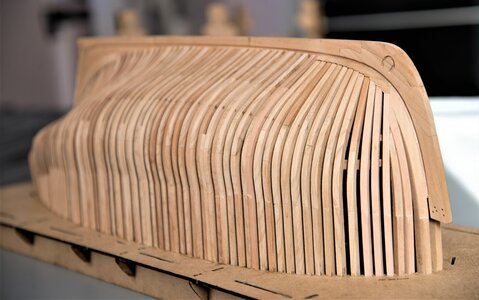
Well..., She is kinda free now, the moment I wait for about half-year, so I can see the frames outside. Again, I must credit @Trident Model for the well-thought design of the frame's construction. They look pretty even and form a smooth transition from the bow to the stern. Take a look at the below photos.
The stern section. When you release the hull from the berth, the parts CL15 are still between the wind and deck transoms. They can easily be removed by twisting. Don't lose them, they will be required soon.
The bow section
This is the berth part after surgery is performed, and the hull being released from it. Don't repeat my mistake, DO NOT glue part CL15!
Both CL15 parts after removing. One of them broke and I have to glue it.
I found another useful way for the berth, you can put the hull upside down, it fits perfectly! This way you can perform light sanding and observations, and yes...some photography.
Well...with the last photo, we have reached the end of this post. The next step is the dustiest work - shaping the hull. I have the mask and hoping it will not require a long time. See you soon... folks, and thank you.
Attachments
Looks fantastic! Great job!Greetings folks! During the past weeks, I have some time to work on the Alert's hull, so without further ado, would love to share the progress with you, my dear readers. But first, my great appreciation to all of you for keeping the interest and being alert to my Alert log.
Well, if you recall from the last post we have finished installing the Breast Hooks and Deck clamps. The next step, Triden's manual suggesting to work and install the Lower beams (Page 26-27). Installing Lower beams assumed to install the Spirit room, Shot locker\Pump well, Magazine access lobby, and Lightroom. Further steps in the manual suggested installing upper deck beams ledges, lodging\hanging knees carlings, and other deck forming parts but...wait, don't we have to shape\sand the external hull? How much dust will the internal structure accumulate after sanding? How easy it will be to remove the dust out thereafter? All those questions\answers lead me to think about temporarily removing the hull from the berth.
So...today's post I will dedicate to releasing the hull from the berth for further shaping. If you would like to follow this path let's begin.
*** Please understand this is not the recommended path from the kit's manual, it is based on my own decision, observations we discussed above, and another Alert build of my friend @Maarten.
It is worth stepping back to the very beginning when we assembled the birth. It seems, and it is actually true, that berth assembly is a very basic and simple process. I recall myself rushing to start the berth assembly and honestly didn't even realize the pitfalls I might meet soon. Let's discuss the image on page 9 instruction manual, specifically Parts CL15.
View attachment 241535
Here we can see that all the parts are labeled with the text 'Fix with glue', all except CL15 parts. The importance of not gluing is so crucial, so... I guess for the shipwrights like myself, the image should depict the message 'Do not fix with glue'!
View attachment 241536
NOT gluing the parts CL15, will make a breeze removing the hull from the berth. Because I glued the parts I presented the challenge to unglue. I use alcohol, acetone, hot water but to no avail. The Elmers Max glue proved to be a great\strong wood glue as being advertised.
View attachment 241540
Once both parts CL15 loosened, I removed all tubs holding the upper berth to the jig, and begin lifting the hull from the bow side, and...bingo, it simply slides out. YAY!!!!
View attachment 241541
Well, She is kinda free now! I wait for this moment for about half-year, just to see how the frames look outside, Again, I must credit @Trident Model for the design of the frame construction. They look pretty even and made a smooth transition from the bow to the stern. Take a look at the below photos.
The stern section
View attachment 241542
View attachment 241543
View attachment 241544
View attachment 241545
The bow section
View attachment 241546
View attachment 241554
View attachment 241547
View attachment 241548
View attachment 241549
This is the berth part after surgery performed prior to being released from the hull. Don't repeat my mistake, DO NOT glue part CL15
View attachment 241550
the CL15 parts after removing
View attachment 241551
I found another useful way if you put the hull upside down to the berth. This way you can perform light sanding and observations
View attachment 241552
Well...with the last photo, we have reached the end of this post. The next step is the dustiest work - shaping the hull. Likely, it didn't require much wood to remove. See you soon...and thank you.

Hallo Jim my friend, very well explained, excellently presented. Very nice frame design, just a super built model, really enjoys watching your work.
HAPPY SANDING - and enjoy it making the final touch of the hull 
Looking very good my friend
Looking very good my friend
As Uwe said Happy sanding!! Although looking at photos you done great job installing ribs etc so shouldn't need that much great job
- Joined
- Oct 19, 2018
- Messages
- 313
- Points
- 278

内板張り 素晴らしいです。...and we continue, We will install the Breast hooks. Again, take a look at the drawings from the AOTS book. They are number 7 in the below image. All Breast hooks bolted to Apron (or false post).
View attachment 239466 View attachment 239467 View attachment 239468
In the kit, those parts identified as BL25, BL26, and BL27 (for the bow section), and BL28 for the stern section. You will need to pay close attention while fitting them. They will require a special angle and as the result a special shape to fit only on your hull. If you want a perfect fit, you will need a great number of fit-and-shape excessive. While shaping the first Breast hook, I accidentally break one. No biggie, I made a new one from scratch. On the top, the broken one.
View attachment 239469 View attachment 239470
Below is the first one installed and bolted.
View attachment 239471
The second Breast hook bolted as well. Use the notch as the guide.
View attachment 239472
The last one for the bow section is installed. While it doesn't have the steps as the first two, its shape is very complex. You have to control the joint part (notch), left and right side as well as the angle.
View attachment 239611
Below is the bow section after installing all three Breast hooks.
View attachment 239476
The last one is the Stern Breats hook.
View attachment 239477 View attachment 239478
Here is the notch for the hook
View attachment 239480
...and it is installed
View attachment 239481
View attachment 239482
View attachment 239483
The final photo of the ship after installing all Breast hooks.
View attachment 239484
That's all for now, I will be happy to see you in the next update where we will discuss the lower hull structure. See you soon and thank you!
English:
Inner boarding is wonderful.
- Joined
- Oct 19, 2018
- Messages
- 313
- Points
- 278
素晴らしいです。 次回の投稿が楽しみです。Greetings folks! During the past weeks, I have some time to work on the Alert's hull, so without further ado, would love to share the progress with you, my dear readers. But first, my great appreciation to all of you for keeping the interest and being alert to my Alert log.
Well, if you recall from the last post we have finished installing the Breast Hooks and Deck clamps. The next step, Triden's manual suggesting to work and install the Lower beams (Page 26-27). Installing Lower beams assumed to install the Spirit room, Shot locker\Pump well, Magazine access lobby, and Lightroom. Further steps in the manual suggested installing upper deck beams ledges, lodging\hanging knees carlings, and other deck forming parts but...wait, don't we have to shape\sand the external hull? How much dust will the internal structure accumulate after sanding? How easy it will be to remove the dust out thereafter? All those questions\answers lead me to think about temporarily removing the hull from the berth.
So...today's post I will dedicate to releasing the hull from the berth for further shaping. If you would like to follow this path let's begin.
*** Please understand this is not the recommended path from the kit's manual, it is based on my own decision, observations we discussed above, and another Alert build of my friend @Maarten.
It is worth stepping back to the very beginning when we assembled the birth. It seems, and it is actually true, that berth assembly is a very basic and simple process. I recall myself rushing to start the berth assembly and honestly didn't even realize the pitfalls I might meet soon. Let's discuss the image on page 9 instruction manual, specifically Parts CL15.
View attachment 241535
Here we can see that all the parts are labeled with the text 'Fix with glue', all except CL15 parts. The importance of not gluing is so crucial, so... I guess for the shipwrights like myself, the image should depict the message 'Do not fix with glue'!
View attachment 241536
Because NOT gluing the parts CL15, will make a breeze removing the hull from the berth. Because I glued the parts I presented the challenge to unglue. I use alcohol, acetone, hot water but to no avail. The Elmers Max glue proved to be a great\strong wood glue as being advertised.
View attachment 241540
Once both parts CL15 loosened, I removed all tubs holding the upper berth to the jig, and begin lifting the hull from the bow side, and...bingo, it simply slides out. YAY!!!!
View attachment 241541
Well, She is kinda free now! I wait for this moment for about half-year, just to see how the frames look outside, Again, I must credit @Trident Model for the design of the frame construction. They look pretty even and made a smooth transition from the bow to the stern. Take a look at the below photos.
The stern section
View attachment 241542
View attachment 241543
View attachment 241544
View attachment 241545
The bow section
View attachment 241546
View attachment 241554
View attachment 241547
View attachment 241548
View attachment 241549
This is the berth part after surgery performed prior to being released from the hull. Don't repeat my mistake, DO NOT glue part CL15
View attachment 241550
the CL15 parts after removing
View attachment 241551
I found another useful way if you put the hull upside down to the berth. This way you can perform light sanding and observations
View attachment 241552
Well...with the last photo, we have reached the end of this post. The next step is the dustiest work - shaping the hull. Likely, it didn't require much wood to remove. See you soon...and thank you.
English translation
Wonderful. I'm looking forward to the next post.
Your hull looks fantastic. Very nice work.
Jan
Jan
- Joined
- Oct 26, 2020
- Messages
- 38
- Points
- 78
...very good explanation - useful especially for coming builders like me (and a "little hint" to Trident). The model looks great, congratulations!
Best regards
Fritz
Best regards
Fritz
Thank you, my friend! I am trying...Looks fantastic! Great job!
Many thanks, Mon Amie! I couldn't be happier to know that the information in the log might be helpful. Yes, despite some minor flaws, the kit is very well designed in mind for a first POF kit.Hallo Jim my friend, very well explained, excellently presented. Very nice frame design, just a super built model, really enjoys watching your work.
Thank you, my dear friend! Yes, my Admiral is not too happy with my first sanding session, contrary, I am not super happy with my 'outside designation by her. It is about +30C those few days. The good thing, it is really not much to sand, just to make everything even...HAPPY SANDING - and enjoy it making the final touch of the hull
Looking very good my friend
Thank you for your comments and welcome to the build log! I hope you will find it informative and usefulEnglish translation
Wonderful. I'm looking forward to the next post.
Many thanks! Yes, there will be dust, but as you mentioned and I visually observed - not too much. I will need just to even the frames to form a nice smooth line. That's the idea ...As Uwe said Happy sanding!! Although looking at photos you done great job installing ribs etc so shouldn't need that much great job
Thank you, Jan! As this is my first POF model, I am learning myself!Your hull looks fantastic. Very nice work.
Hallo, Fritz. I am grateful for your comments and happy to know that you find the explanation details useful....very good explanation - useful especially for coming builders like me (and a "little hint" to Trident). The model looks great, congratulations!
To all who keep reading, Many thanks, I can assure, that will try to make the log as much informative in the future, But please, don't forget about the critics they are valuable as much.
Hi Jim,Greetings folks! During the past weeks, I have some time to work on the Alert's hull, so without further ado, would love to share the progress with you, my dear readers. But first, my great appreciation to all of you for keeping the interest and being alert to my Alert log.
Well, if you recall from the last post we have finished installing the Breast Hooks and Deck clamps. The next step, Triden's manual suggesting to work and install the Lower beams (Page 26-27). Installing Lower beams assumed to install the Spirit room, Shot locker\Pump well, Magazine access lobby, and Lightroom. Further steps in the manual suggested installing upper deck beams ledges, lodging\hanging knees carlings, and other deck forming parts but...wait, don't we have to shape\sand the external hull? How much dust will the internal structure accumulate after sanding? How easy it will be to remove the dust out thereafter? All those questions\answers lead me to think about temporarily removing the hull from the berth.
So...today's post I will dedicate to releasing the hull from the berth for further shaping. If you would like to follow this path let's begin.
*** Please understand this is not the recommended path from the kit's manual, it is based on my own decision, observations we discussed above, and another Alert build of my friend @Maarten.
It is worth stepping back to the very beginning when we assembled the birth. It seems, and it is actually true, that berth assembly is a very basic and simple process. I recall myself rushing to start the berth assembly and honestly didn't even realize the pitfalls I might meet soon. Let's discuss the image on page 9 instruction manual, specifically Parts CL15.
View attachment 241535
Here we can see that all the parts are labeled with the text 'Fix with glue', all except CL15 parts. The importance of not gluing is so crucial, so... I guess for the shipwrights like myself, the image should depict the message 'Do not fix with glue'!
View attachment 241536
Because NOT gluing the parts CL15, will make a breeze removing the hull from the berth. Because I glued the parts I presented the challenge to unglue. I use alcohol, acetone, hot water but to no avail. The Elmers Max glue proved to be a great\strong wood glue as being advertised.
View attachment 241540
Once both parts CL15 loosened, I removed all tubs holding the upper berth to the jig, and begin lifting the hull from the bow side, and...bingo, it simply slides out. YAY!!!!
View attachment 241541
Well, She is kinda free now! I wait for this moment for about half-year, just to see how the frames look outside, Again, I must credit @Trident Model for the design of the frame construction. They look pretty even and made a smooth transition from the bow to the stern. Take a look at the below photos.
The stern section
View attachment 241542
View attachment 241543
View attachment 241544
View attachment 241545
The bow section
View attachment 241546
View attachment 241554
View attachment 241547
View attachment 241548
View attachment 241549
This is the berth part after surgery performed prior to being released from the hull. Don't repeat my mistake, DO NOT glue part CL15
View attachment 241550
the CL15 parts after removing
View attachment 241551
I found another useful way if you put the hull upside down to the berth. This way you can perform light sanding and observations
View attachment 241552
Well...with the last photo, we have reached the end of this post. The next step is the dustiest work - shaping the hull. Likely, it didn't require much wood to remove. See you soon...and thank you.
A very nice transition of the frame. And during the sanding you are gone love the shape more and more. Let her rest on your knees and let your hands flow over here curves!
Regards, Peter
Amen! Echt heel erg bedankt, Peter!Hi Jim,
A very nice transition of the frame. And during the sanding you are gone love the shape more and more. Let her rest on your knees and let your hands flow over here curves!
Regards, Peter
Set the controls for the heart of the sun
The heart of the sun, the heart of the sun
Hmmm...mmm....I hope we are thinking of the same 'her'!A very nice transition of the frame. And during the sanding you are gone love the shape more and more. Let her rest on your knees and let your hands flow over here curves!
In any case, let it be!!!Oh Yes, Jim. In your build (and after the previous discussions) this ship is 'female’ and she’s the ‘her’.Hmmm...mmm....I hope we are thinking of the same 'her'!
I wouldn't dare to think otherwise.

And indeed: “Set the controls ........
Regards, Peter
Framing looks great, Jim! Beautiful work.
I have on question though, not related to your work. It seems that it was a common practice in British warships of the era to have keel tapered both fore and aft, resulting in fore and aft deadwood tapered as well. That's shown in Goodwin's monograph. It seems, from pictures, that keel, stem and sternpost are not tapered. I didn't do any tapering on Cheerful either. Makes me wonder if these tapers are necessary to achieve proper shape of the hull. Many thanks for sharing.
I have on question though, not related to your work. It seems that it was a common practice in British warships of the era to have keel tapered both fore and aft, resulting in fore and aft deadwood tapered as well. That's shown in Goodwin's monograph. It seems, from pictures, that keel, stem and sternpost are not tapered. I didn't do any tapering on Cheerful either. Makes me wonder if these tapers are necessary to achieve proper shape of the hull. Many thanks for sharing.