The Naval Cutter ALERT- 1777, POF by Jimsky

I have on question though, not related to your work. It seems that it was a common practice in British warships of the era to have keel tapered both fore and aft, resulting in fore and aft deadwood tapered as well. That's shown in Goodwin's monograph. It seems, from pictures, that keel, stem and sternpost are not tapered. I didn't do any tapering on Cheerful either. Makes me wonder if these tapers are necessary to achieve proper shape of the hull. Many thanks for sharing.

@Gennaro Many thanks for the comment, and wonderful question. :)

During the eighteenth and early nineteenth centuries, there were two schools of practice. Some builders produced ships with the stem increasing in width from heel to head, the heel being made the width of the keel at its fore-end, increasing to twice that width at the head. The alternative practice was to have the width remaining the same to the height of the lower gundeck, or equivalent deck, and then broadening out to twice its width at its heel. ( From Peter Goodwin -Saling Man Of War 1650 -1850)

On Alert 1777, we can see that sternpost has the taper towards the keel. However, the stem post doesn't have the taper.

From AOTS book Alert 1777 by P.Goodwin
1625174359924.png 1625175174901.png

From Trident's manual, the kit depicts the taper at the Sternpost and doesn't have a taper at the Stem.
1625174520964.png

From my model at earlier stages
600_0663.JPG

Hope it cleared some shades on your dilemma. Happy Modeling!
 

Attachments

  • 1625175196697.png
    1625175196697.png
    57.7 KB · Views: 6
@Gennaro Many thanks for the comment, and wonderful question. :)

During the eighteenth and early nineteenth centuries, there were two schools of practice. Some builders produced ships with the stem increasing in width from heel to head, the heel being made the width of the keel at its fore-end, increasing to twice that width at the head. The alternative practice was to have the width remaining the same to the height of the lower gundeck, or equivalent deck, and then broadening out to twice its width at its heel. ( From Peter Goodwin -Saling Man Of War 1650 -1850)

On Alert 1777, we can see that sternpost has the taper towards the keel. However, the stem post doesn't have the taper.

From AOTS book Alert 1777 by P.Goodwin
View attachment 241715 View attachment 241720

From Trident's manual, the kit depicts the taper at the Sternpost and doesn't have a taper at the Stem.
View attachment 241716

From my model at earlier stages
View attachment 241719

Hope it cleared some shades on your dilemma. Happy Modeling!
Thanks so much for detailed explanation. In the end, taper does not affect steps for cant frames whatsoever. Why did they bother with such a minuscule taper? Hydrodynamics? Thanks again, much appreciated.
 
Greetings folks! During the past weeks, I have some time to work on the Alert's hull, so without further ado, would love to share the progress with you, my dear readers. But first, my great appreciation to all of you for keeping the interest and being alert to my Alert log.

Well, if you recall from the last post we have finished installing the Breast Hooks and Deck clamps. The next step, Triden's manual suggesting to work and install the Lower beams (Page 26-27). Installing Lower beams assumed to install the Spirit room, Shot locker\Pump well, Magazine access lobby, and Lightroom. Further steps in the manual suggested installing upper deck beams ledges, lodging\hanging knees carlings, and other deck forming parts but...wait, don't we have to shape\sand the external hull? How much dust will the internal structure accumulate after sanding? How easy it will be to remove the dust out thereafter? All those questions\answers lead me to think about temporarily removing the hull from the berth.

So...today's post I will dedicate to releasing the hull from the berth for further shaping. If you would like to follow this path let's begin.
*** Please understand this is not the recommended path from the kit's manual, it is based on my own decision, observations we discussed above, and another Alert build of my friend @Maarten.

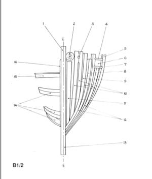
It is worth stepping back to the very beginning when we assembled the birth. It seems, and it is actually true, that berth assembly is a very basic and simple process. I recall myself rushing to start the berth assembly and honestly didn't even realize the pitfalls I might meet soon. Let's discuss the image on page 9 instruction manual, specifically Parts CL15.

View attachment 241535

Here we can see that all the parts are labeled with the text 'Fix with glue', all except CL15 parts. The importance of not gluing is so crucial, so... I guess for the shipwrights like myself, the image should depict the message 'Do not fix with glue'!

View attachment 241536

NOT gluing the parts CL15, will make a breeze removing the hull from the berth. I made a mistake and glued both parts, therefore, no easy removing for Jim. I use alcohol, acetone, hot water to soften the glue, but to no avail. The Elmers Max glue proved to be a great\strong wood glue as being advertised by the manufacturer. ;) I ended up using the fresh\sharp scalpel blade #11 and cut along the edges. I cannot say I succeeded without the damage, and one of the parts broke, but parts were loosened enough to proceed.

View attachment 241540

Once both parts CL15 loosened, I removed all tabs (CL36) holding the upper berth to the jig, and begin lifting the hull from the bow side, and...bingo, it simply slides out. YAY!!!!

View attachment 241541

Well..., She is kinda free now, the moment I wait for about half-year, so I can see the frames outside. Again, I must credit @Trident Model for the well-thought design of the frame's construction. They look pretty even and form a smooth transition from the bow to the stern. Take a look at the below photos.

The stern section. When you release the hull from the berth, the parts CL15 are still between the wind and deck transoms. They can easily be removed by twisting. Don't lose them, they will be required soon.
View attachment 241542
View attachment 241543
View attachment 241544
View attachment 241545

The bow section
View attachment 241546
View attachment 241554
View attachment 241547
View attachment 241548
View attachment 241549

This is the berth part after surgery is performed, and the hull being released from it. Don't repeat my mistake, DO NOT glue part CL15! :p

View attachment 241550

Both CL15 parts after removing. One of them broke and I have to glue it.

View attachment 241551
I found another useful way for the berth, you can put the hull upside down, it fits perfectly! This way you can perform light sanding and observations, and yes...some photography. ;)

View attachment 241552

Well...with the last photo, we have reached the end of this post. The next step is the dustiest work - shaping the hull. I have the mask and hoping it will not require a long time. See you soon... folks, and thank you.
Thank you for your affirmation. We will continue to upgrade the design of the auxiliary framework in the next kit. One more thing to say, your production is great!
 
Wonderfull work Jim, this is certainly an enjoyable moment.
If you presanded your frames correctly you dont have too much sanding to do.
Thank you, my friend! Your statement about the preshaped frames is absolutely true. You should not underestimate the makes of frames using supplied templates and jigs. :)
 
Well done, another out of the mold.

Be warned that with out the cross beams the ribs may move horizontally. I found that they hold quite well and a large flat wall plaster hand sander will do the shaping job well. You can press quite hard, They shape up quickly and the wood is a joy to sand( no tearing).
Check the Rbb joints for any de gluing and that they are still spaced correctly.
Point well taken, Paul!! Many thanks for the tip. I observe some 'loose' frames and reinforced them with additional glue. Now into the shaping process! YAY!
 
Hello folks. Summertime taking away some of the modeling hours, and is dedicated to outside activities. However, I still managed to find some time and continue with our Alert assembly journey. I would like to make sure I will not forget to thanks everyone for your interest and valuable comments. Thank you ALL! :)

This probably will be the shortest post in writing, but the biggest post in photos. I have mentioned in a previous post that frames laid out pretty well, and my initial observation proved this. I didn't have to sand much just make it even and smooth. To complete this task I used self-made sanding sticks, foam board, and rubber shapes. The sticks were made out of 12.00 mm ply and have various widths\length. The sandpaper is attached using double-sided sticky tape. On the first side of the stick\board, I have 150 grit sandpaper, on the opposite side - 280 grit. The foam board (on the right) has 320 grit paper on a single side.

Most work done using the straight boards\sticks
600_2348.jpg 600_2350.jpg

In irregular forms, I use the rubber shapes covered with sandpaper, foam board, and foam blocks (yellow)

600_2349.jpg

Both, Starboard and Port took roughly no more than 3 hours, and I was happy with the result. Please note, that images are made during different times of the day. Also, some of the images were made while applying white spirit to the frames, just to see how the timber will look under the oil. And now are the images.

600_1538.jpg
600_1547.jpg
600_1543.jpg600_1541.jpg
600_1542.jpg
600_1544.jpg
600_1552.jpg600_1549.jpg
600_1553.jpg

600_1556.jpg
600_1565.jpg

600_1578.jpg
600_1557.jpg
600_1569.jpg

Continue in the next post due to the images limit
 
Hello folks. Summertime taking away some of the modeling hours, and is dedicated to outside activities. However, I still managed to find some time and continue with our Alert assembly journey. I would like to make sure I will not forget to thanks everyone for your interest and valuable comments. Thank you ALL! :)

This probably will be the shortest post in writing, but the biggest post in photos. I have mentioned in a previous post that frames laid out pretty well, and my initial observation proved this. I didn't have to sand much just make it even and smooth. To complete this task I used self-made sanding sticks, foam board, and rubber shapes. The sticks were made out of 12.00 mm ply and have various widths\length. The sandpaper is attached using double-sided sticky tape. On the first side of the stick\board, I have 150 grit sandpaper, on the opposite side - 280 grit. The foam board (on the right) has 320 grit paper on a single side.

Most work done using the straight boards\sticks
View attachment 249629 View attachment 249630

In irregular forms, I use the rubber shapes covered with sandpaper, foam board, and foam blocks (yellow)

View attachment 249631

Both, Starboard and Port took roughly no more than 3 hours, and I was happy with the result. Please note, that images are made during different times of the day. Also, some of the images were made while applying white spirit to the frames, just to see how the timber will look under the oil. And now are the images.

View attachment 249639
View attachment 249640
View attachment 249642View attachment 249641
View attachment 249643
View attachment 249644
View attachment 249646View attachment 249645
View attachment 249647
View attachment 249648
View attachment 249649
View attachment 249650
View attachment 249652
View attachment 249653
View attachment 249654
View attachment 249655

Continue in the next post due to the images limit

Precise workmanship, a joy to behold ! Your attention to detail is amazing. I'll continue to learn by following your build, Jim. Thanks.
 
Looks fantastic Jimsky!!! Should be out of the jig soon?
Thanks, Mon Amie. She does require some work completed. Most likely not before outer and ceiling planking from one side. Then, she will be free for other tasks. But...she is partially free, and I can remove her from the berth at any time. ;)
 
Amazing Jim. These photos make we want to build a POF kit! The amount of work that went into manufacturing those frames Redface ..
Thank you, my friend. As far as I already learn, POF is a completely different experience compared with POB build. Building the frames requires some precision and is considered as challenging task. In the same token, if you build frames the 'right' way you will be rewarded with the beautiful hull shape.
Trident Model supplies special templates for all frames to build. It much simplifies the process of assembling and makes it fun, instead of a challenge. Now, I understand why Triden Model designates this kit as the first-ever POF kit.
 
Continue from the previous post

View attachment 249680
View attachment 249681
View attachment 249682
View attachment 249659
View attachment 249660
View attachment 249661
View attachment 249663
View attachment 249664
View attachment 249665

I didn't use any fine sandpaper yet, This will be done later, after installing the ceiling. Thanks again for your interest, will talk to you soon.
That is an impressively dense nest of frames. I don't have a lot of background in other ships but f ar more than I recall seeing before. Quite a challenge and well done. Rich (PT-2)
 
Back
Top