HMS Victory of Caldercraft by Wil

1e planking


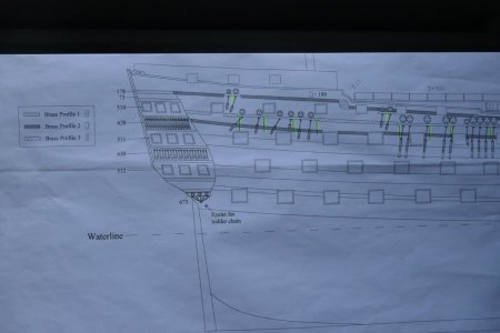
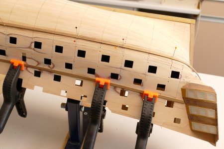
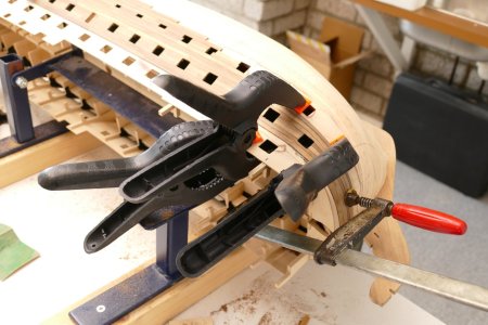
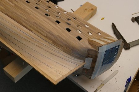
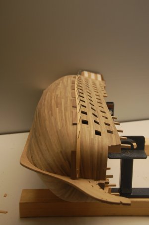
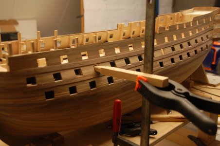
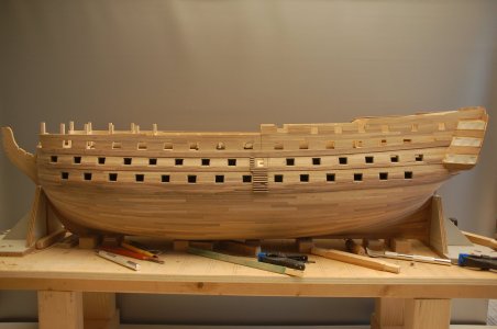
After the glue hardened, a first start was made with the 1.5 mm plywood strips with the gun ports. The building instructions indicate to start with the top and largest strip (part 270). But what will be the height?
At first, I positioned the strip dry against the hull, making sure that on the second deck, the distance between the gun ports and the deck would be the same everywhere. After all, you have to start somewhere.

View attachment 497015

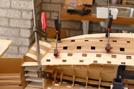
The construction description indicated that careful attention had to be paid to the correct fitting of the pattern of the gun ports. This is because this must match the holes in the strips that will later be fitted to the inside of the upper gun deck, aft deck and inner bulwark (parts 273, 274, 275 and 276). So dry-fitted these immediately. For imaging purposes, I first put in the upper gun deck and Quarter deck. I kept the upper gun deck flush with the top of strip 276. This best matches my first impression.

What turns out: part 276 gears up at the bow all the way with the deck. The deck rests on the supports in the bulkheads. The middle part 274 fits reasonably well and the rear part 273 also fits well, but is too short. It became a bit of a search for the golden mean.

View attachment 497016

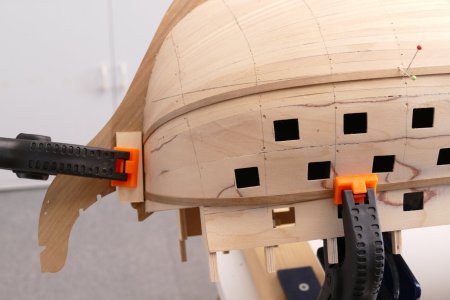
I have filled the spaces in the bow against bulkhead 1 with plywood scraps. I deliberately chose plywood here because I believe it is better than balsa when profiling. If balsa is used, the difference in hardness with the plywood parts of the hull seems too great to me, which makes profiling less fine. Anyway, profiling went perfectly after the glue hardened. First using the cutter in the Dremel for the coarse work and then post-profiling with the sanding slats I made.

With the hull in the correct position in the stand, I also had ideal visibility of the correct chamfer of the trusses. Before I started profiling, I briefly taped off the walnut of the keel to prevent damage and blacked out the spaces for the dummy barrel strips.

View attachment 497017

After doing some study on first planking and looking at other construction reports, I chose to let the planks flow in their natural shape over the rafters. This is in contrast to the classic method, where all planks are evenly distributed over the bulkheads.

Measured from the keel, I fixed every 4e plank on the bulkheads with nails (pre-drill first).
The starting point here is that between bulkheads 5 and 10, the course between the bulkheads is reasonably even, so that the boards can be applied in their full width in that zone. Outside this zone, a natural continuation to the bow and the stern is always given with a slight bend at right angles to the bulkheads. In doing so, particular care was taken to ensure that the planks connect well with the bulkheads and that no additional lateral pressure or steering is given to the planks.

View attachment 497018

Then, for each bulkhead, all mutual distances between the different slats were measured and processed in a spreadsheet. This spreadsheet is set up so that the entire course of 4 planks is distributed over these 4 planks each time. So in practice, clusters of 4 equally shaped planks were made each time to cover the measured strip.

I did the bending of the planks with pliers, where you squeeze a kind of notch on the inside, giving the lath little kinks, so to speak. If you use the pliers perpendicular to the batten, you get a straight bend. If you do this at an angle, you get a twisted bend. Works really super fast. However, this method is not suitable for the second planking.

View attachment 497019

After marking out, I started the first planking. I started on the keel side, with the first series of 4 planks. At the bow and stern, I had to start inserting the planks right away because the natural course of the planks causes them to fan out.
I secure the boards in a number of places with nails, which I pre-drill first. In between, where little force is needed, I use clamps, into which I have glued a paper clip. Where there is more tension on the boards, I use small to large spring clamps for fixation.

View attachment 497020

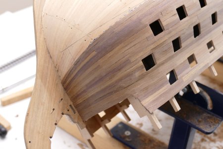
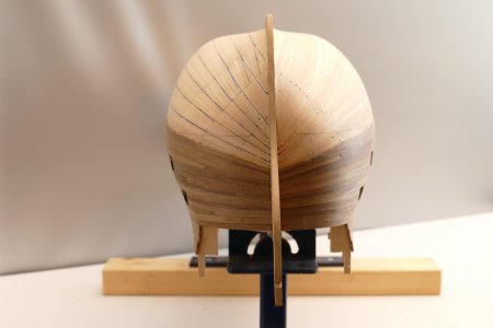
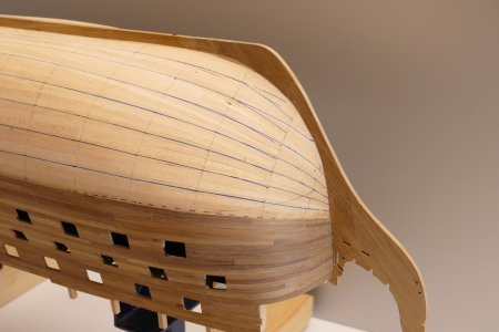
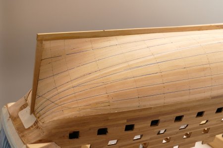
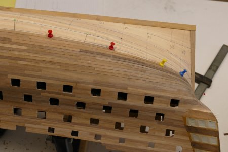
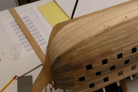
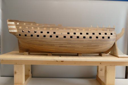
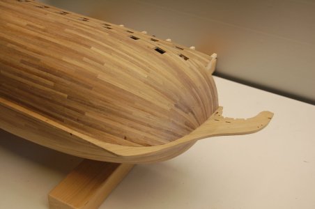
The first planking has been completed, all planks are on and this has closed the space under the upper gun deck. In the end, I had to conclude that this part of the project did not disappoint me. It did go slowly because of the drying time in between, but gradually it proved possible to tackle port and starboard simultaneously.

View attachment 497021

View attachment 497022

View attachment 497023

Despite the many (measuring) preparations, after each series of 4 planks, it still proved necessary to measure and recalculate again, in order to eventually maintain the natural gradient in the planks. The sanding could then begin.

A day with lots of rain, used to sand the 1e hull planking into the right shape. I must honestly say that the tilt tool proved its services here. The hull stands stable as a house. This way, you have both hands free to tackle this intensive job vigorously. In about 3 hours, the whole job was done.
My aim of not having to use putty in the end succeeded. I was worried that the concave angle between the top and middle patterns would require additional measures, but on reflection, that was not necessary. With a rounded sanding block, there was enough material in the plywood to get the curve right.
This also applies to the convex curve between the lower and middle strip. This is slightly easier in terms of sanding, but of course you are not supposed to sand right through the plywood.
I first countersunk the brass nails, which were used to attach the strips to the hull, with a dowel.

View attachment 497024

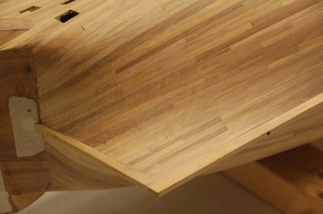
What is still noticeable is that some kinks did appear here and there when applying the strips. The stains in the plywood show this nicely, if you sand long enough. My advice is "don't be too economical with sanding", it will certainly benefit the final shape.

Excellent start, congrats
Indeed your home made stand makes a lot of sense.
 
The facia and galleries

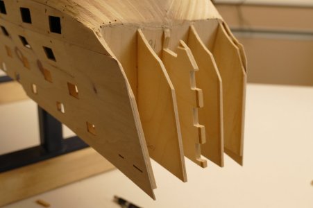
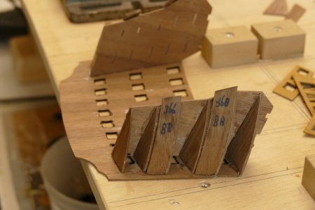
For the dimensions of the galleries and fascia, I assumed the edges of the shields with gun ports. I thickened all plywood parts on bulkhead 18 with the length difference between the bulkheads and the shields. This thickening is the same on all parts!

P1300121.JPG

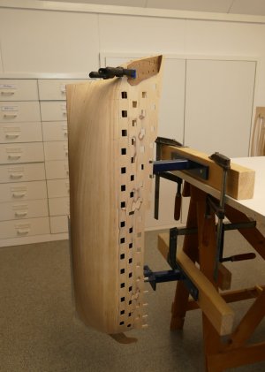
For the work on the galleries and fascia, I placed the hull completely vertical to make the work on the galleries and fascia clear and ergonomic.

P1300124 (2).JPG

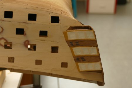
After much fitting and measuring, I had now got the bases for the galleries attached to the fuselage. I fixed the base plates of the galleries to the side of the hull with two small nails, keeping in mind the slotted holes in the shields. Then with the two top quarter galleries, I determined the exact position of the fascia and fixed these to the keel with two small nails as well.

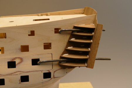
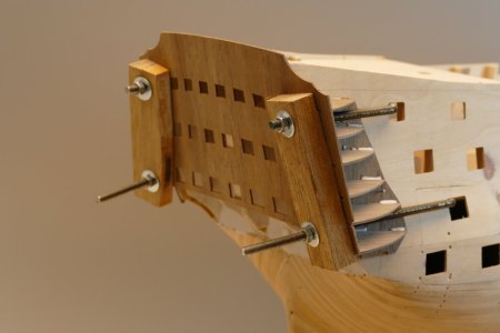
To be able to bend the fascia into the right curve around the poop deck while getting and keeping the other quarter galleries in place, I used 4 tie rods running through the lower and upper windows. Here a batten against this and screw it on. The advantage is that by tightening or loosening the nuts, some space can be created alternately to get and keep the quarter galleries with their lugs in place.

Once everything was in place and I had checked again that it all connected straight and logically to the fuselage, I applied glue to the quarter galleries with an injection needle.

P1300135.JPG

P1300138.JPG

After the glue had hardened, the 6 nails went out and the whole section could be taken right off the hull. After further work on the galleries, this part in its entirety could finally be glued back onto the fuselage.

P1300148.JPG

Before fitting the skin panels of the galleries, I was in doubt about the glazing of the galleries. I saw various designs and approaches in the various construction reports.
- With and without glass
- Pre-painted or not
- External rebate
- Painting inside galleries

If I wanted to make something decent out of it, I couldn't escape the fact that the skin panels had to be sanded and putty after application, before being painted black. At a later stage, the brasswork will come over this.
The build description indicates that the glass had to be applied on the inside, before fitting the skin panels. But that stuff is awfully static. Won't that make a big mess in those windows with all that sanding, even in later stages of the project?

At the time, I tackled this as follows
- Bending skin panels and precise tailoring
- Blackening the day edges and rebates
- Glass against it
- Skin panels mounted and windows taped
- Then filler and sand and possibly pre-paint
- Keeping windows taped throughout the process
- This approach, of course, also applies to fascia

After glazing the window sections, the fitting and measuring began with the 5 outer shields per gallery. I completely taped off the window sections in the galleries and the fascia to avoid as much contamination as possible during the process.

P1300156.JPG

 
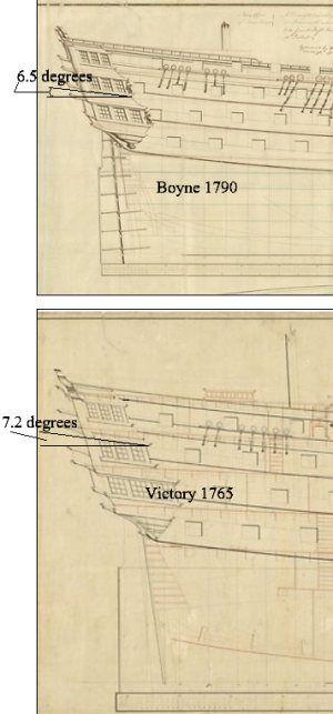
I think the angle of the galleries was more in keeping with the sheer of the planking. The below contemporary plans examples from RMG are Victory (100) 1765 and Boyne (98) 1790.
Allan
1738240785338.png
 
Last edited:
I think the angle of the galleries was more in keeping with the sheer of the planking. The below contemporary plans examples from RMG are Victory (100) 1765 and Boyne (98) 1790.
Allan

If you read the first post....

Except for fitting a few fragile parts, the hull is completely finished and I started making the masts this week.
 
If you read the first post....

It would indeed be difficult to fix this error at this stage, but not impossible. My thoughts were not so much to change things at this late stage but rather to identify it for future builds/builders. I do wonder if this is a mistake in the plans/instructions.
Allan
 
It would indeed be difficult to fix this error at this stage, but not impossible. My thoughts were not so much to change things at this late stage but rather to identify it for future builds/builders. I do wonder if this is a mistake in the plans/instructions.
Allan
Hello Allen,

Thank you for your engagement. I understand your intention to warn future builders.
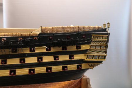
I think the angle at which the photos are taken is very decisive for the picture that emerges, especially when you look at the galleries, in relation to the entire hull. I took another photo at eye level of the galleries and one of Caldercraft's drawing. My interpretation is that my model is correct with the drawing, namely that the galleries run almost horizontally. Incidentally, this also seems logical to me because, as I recall, in reality the floors of the officers' quarters behind them also run horizontally.
Adjustments are no longer an issue. When I look back at how the galleries came about, this is almost impossible to do even in the construction phase. Well if you build scratch, then you have all the freedom, but not with a construction kit.
Still, thanks for your input.

P1034284.JPG

P1034285.JPG
 
Hi Wil,
I checked a number of additional contemporary plans, and based on those it appears the Caldercraft drawings are wrong. No matter, if you are happy, that is what a hobby is all about. :)
Allan
 
Last edited:
2e Planking

The next step in the process is the 2e planking, which I wanted to tackle as follows:
To start with, I plotted the waterline and the top of the upper wales on the hull. These lines are easy to measure out from the drawings provided. For the gunwale, I used the gun ports as a starting point.
I then transferred the position of the bulkheads to the hull.
The idea is to follow the curved line of the wale until I end up at the waterline roughly in the middle of the hull. From there, I'm going to measure the distances per bulkhead and divide by the number of planks. Then measure these measurements out on the hull and use them as a basis to rejoint the planks.

For the length of the planks, I assumed a "trade length" at the time of 30 ft, about 9 m, I thought I read somewhere. At a scale of 1:72, this equates to 125 mm.
The walnut slats, supplied by Caldercraft, are 5.2 mm wide. Converted, that's 37.4 cm. A length of 9 metres is then comparatively realistic, although in practice we are talking about huge planks.
As the moment of truth of the 2e planking began to approach and the first planks were about to be put on, there were still a number of questions for me to answer.

If I measure the distances on each rafter between top of wale and the waterline on my hull, from bulkhead 1 to 10 it is almost constant, about 85 mm. Then towards bulkhead 17 it increases to about 110 mm. So here, on the stern, it needs to be widened considerably by applying stealers.

The pictures below show the situation on my hull, on both bow and stern sides.
When I wanted to use a walnut strip for the 2e planking to follow the line for the upper wale, I noticed that this involves considerable bending stresses in the flat plane at both ends. The same appeared to be the case when following the waterline. True, the strip was dry and if made wet will probably react differently. With a whole length this can be made into a smooth line in practice, but with all short pieces of 125 mm this becomes a lot more difficult.

Something in me said this doesn't make sense. I suppose that in the past, planks were mainly bent in the vertical plane and then planed in line widthways. In other words try to get the strips in a natural shape, without bending stress in the flat plane against the hull, which will make them fit nicely with the 1e planking and better ensure a smooth line.
P1300183.JPGP1300183.JPG

P1300184.JPG

The above pictures show well the consequence.
At the rear, the distance between the upper and lower strip remains almost constant, which is favourable.
At the front, I have to narrow the planks considerably. An additional advantage here is that I then create a longer tangent plane under the lower strip, against the keel, so that the connecting planks can remain somewhat wider there.

For the wales in the Victory model, I don't think it matters, they will be glued to the 2e planking at a later stage.

In between, some investment in the yard.
A few weeks earlier, I was looking for a disc sander. Looking on the internet and immediately bumped into an advert from Lidl. On sale for €45. Added some sanding discs and for a good € 50,= I was the man. Great little machine, variable speed and can be connected to the hoover.

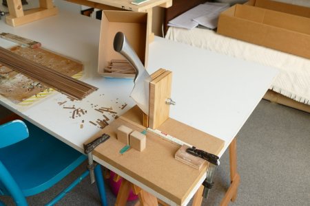
Also started cutting the planks for the 2e planking. The cutting device I had bought a few months earlier turned out to be not ideal. Not stable enough (plastic) and the blades, although sharp, were also very thin. Result with the walnut was that pieces quickly broke out of the blade. Drama. Bad buy, in other words.

Suddenly I realised that somewhere in a cupboard there must be a razor-sharp Japanese kitchen knife. Once purchased, but hardly ever used. You know the drill. Thought for a moment about how to tackle this.
Well, it has become a veritable guillotine. Is razor-sharp and cuts great, but above all is very stable in size. A stockpile of 600 boards for the 2e lining was arranged in no time afterwards.


P1300186.JPG

As I mentioned, I had shortened a stock of planks with the guillotine. I then made a start on the 2e planking. I started with a row of planks along the line of the upper wale. At the front and back of the ship, the planking deviates from this line because I want the planks to make a natural curve. Until then, everything was going according to plan. Bending the planks I did with a soldering bold, after first putting the planks in water for a few hours. The photo below shows the progress.

P1300193.JPG

The blue dotted line is the end of this first phase. From here on, a different sizing applies and I will use Petr's method. The black pencil line is the water line.

After 2 weeks of 48 hours of hard work, the 2e planking above the waterline was on the starboard and port sides. Quite a job, which did not disappoint me, I must say.

The pictures below show very well how I proceeded. These also show that I made enthusiastic use of the gun ports to hook in my glue clamps. There would be a lot more of this later when completing the 2e planking below the waterline

P1300191.JPG

P1300192.JPG

After completing the planking all the way to the waterline, I scraped the surface lies. Such that it is not perfectly smooth. With this, I tried to approach the situation as I think it was before. The intention was thus to leave some unevenness visible in the planks. I hoped this would be reflected later after the hull is painted.
The following photos gives a good idea of the final result above the waterline.

P1300202.JPG

P1300213.JPG

Earlier, I indicated that I wanted to follow Petr's method below the waterline. This would mean that I would have to divide the distances across all bulkheads from the existing planking to the keel by 32 planks everywhere. When I calculated this and drew the results on the hull, this clearly gave problems with this model at the bow and stem. This can be clearly seen by the lines that stop suddenly on the hull. These curves cannot be made without huge horizontal stresses in the planks.

P1300208.JPG

P1300209.JPG

I therefore chose to follow the natural curve here anyway. At the stem, I therefore had to start using stealers. Nice learning project again. In fact, a continuation of the method I followed above the waterline.

In retrospect, when planking the section above the waterline, I already made an essential mistake by not following the rules for planking an English ship. By following the natural bending of the planks, I started rejointing too early. In reality, rejointing only starts below the lower wale.
However, you have to learn from your mistakes people often say, but from my mistakes others can also learn. That is also the motto of this forum. That is why I have tried to analyse things to see what went right and what did not. An extensive analysis can be seen in my Dutch construction report https://www.modelbouwforum.nl/threads/hms-victory-van-caldercraft-door-wil.281364/page-7

My conclusion at the time:
If I want to do it completely according to the rules, I will have to take off the entire 2e planking, which I have applied so far, and start with the lower wale, of thicker material. However, this is going way too far for me.
Three quarters of the hull will soon be covered in paint or copper. I want to leave the last quarter (one side below the waterline) transparent without copper for now. Here I want to show what I have to offer as a modeller, rather than following the official planking pattern. Applying tapered boards and stealers nice and tight was hard enough.

Meanwhile, I had managed to spend quite a few hours on my Victory again. The second planking is almost halfway done. I managed to keep things straight and the lines of the planks flowing quite nicely. It took me about an hour on average to get one plank on from bow to stern. Total 64 to go, of which 24 were done at that point. I am satisfied with my choice to continue my way, although I would have loved to compete with the other method. But fortunately, it is not a competition. The pictures below give a nice result so far.

P1300243.JPG

P1300244.JPG

P1300246.JPG

After few more days of hard work on the 2e planking, this project is now complete. After the glue hardened, I lightly scraped the planking. Below is an impression of what it has become.

P1300250.JPG

DSC_4213.JPG

DSC_4214.JPG

As I mentioned, I wanted to copper plating my ship below the waterline on one side and finish the other side transparently, I think with danish oil. The question of which side and how, hung in the air for a while. Of course, the prettiest side had to be oiled. However, the answer to this question came sooner than I thought. When scraping the last piece of the 2e planking, I actually got through the walnut. Needless to say, this side was going to be coppered.
 
2e Planking

The next step in the process is the 2e planking, which I wanted to tackle as follows:
To start with, I plotted the waterline and the top of the upper wales on the hull. These lines are easy to measure out from the drawings provided. For the gunwale, I used the gun ports as a starting point.
I then transferred the position of the bulkheads to the hull.
The idea is to follow the curved line of the wale until I end up at the waterline roughly in the middle of the hull. From there, I'm going to measure the distances per bulkhead and divide by the number of planks. Then measure these measurements out on the hull and use them as a basis to rejoint the planks.

For the length of the planks, I assumed a "trade length" at the time of 30 ft, about 9 m, I thought I read somewhere. At a scale of 1:72, this equates to 125 mm.
The walnut slats, supplied by Caldercraft, are 5.2 mm wide. Converted, that's 37.4 cm. A length of 9 metres is then comparatively realistic, although in practice we are talking about huge planks.
As the moment of truth of the 2e planking began to approach and the first planks were about to be put on, there were still a number of questions for me to answer.

If I measure the distances on each rafter between top of wale and the waterline on my hull, from bulkhead 1 to 10 it is almost constant, about 85 mm. Then towards bulkhead 17 it increases to about 110 mm. So here, on the stern, it needs to be widened considerably by applying stealers.

The pictures below show the situation on my hull, on both bow and stern sides.
When I wanted to use a walnut strip for the 2e planking to follow the line for the upper wale, I noticed that this involves considerable bending stresses in the flat plane at both ends. The same appeared to be the case when following the waterline. True, the strip was dry and if made wet will probably react differently. With a whole length this can be made into a smooth line in practice, but with all short pieces of 125 mm this becomes a lot more difficult.

Something in me said this doesn't make sense. I suppose that in the past, planks were mainly bent in the vertical plane and then planed in line widthways. In other words try to get the strips in a natural shape, without bending stress in the flat plane against the hull, which will make them fit nicely with the 1e planking and better ensure a smooth line.

View attachment 499529View attachment 499529

View attachment 499530

The above pictures show well the consequence.
At the rear, the distance between the upper and lower strip remains almost constant, which is favourable.
At the front, I have to narrow the planks considerably. An additional advantage here is that I then create a longer tangent plane under the lower strip, against the keel, so that the connecting planks can remain somewhat wider there.

For the wales in the Victory model, I don't think it matters, they will be glued to the 2e planking at a later stage.

In between, some investment in the yard.
A few weeks earlier, I was looking for a disc sander. Looking on the internet and immediately bumped into an advert from Lidl. On sale for €45. Added some sanding discs and for a good € 50,= I was the man. Great little machine, variable speed and can be connected to the hoover.

Also started cutting the planks for the 2e planking. The cutting device I had bought a few months earlier turned out to be not ideal. Not stable enough (plastic) and the blades, although sharp, were also very thin. Result with the walnut was that pieces quickly broke out of the blade. Drama. Bad buy, in other words.

Suddenly I realised that somewhere in a cupboard there must be a razor-sharp Japanese kitchen knife. Once purchased, but hardly ever used. You know the drill. Thought for a moment about how to tackle this.
Well, it has become a veritable guillotine. Is razor-sharp and cuts great, but above all is very stable in size. A stockpile of 600 boards for the 2e lining was arranged in no time afterwards.


View attachment 499531

As I mentioned, I had shortened a stock of planks with the guillotine. I then made a start on the 2e planking. I started with a row of planks along the line of the upper wale. At the front and back of the ship, the planking deviates from this line because I want the planks to make a natural curve. Until then, everything was going according to plan. Bending the planks I did with a soldering bold, after first putting the planks in water for a few hours. The photo below shows the progress.

View attachment 499532

The blue dotted line is the end of this first phase. From here on, a different sizing applies and I will use Petr's method. The black pencil line is the water line.
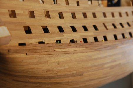
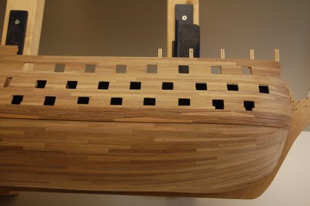
After 2 weeks of 48 hours of hard work, the 2e planking above the waterline was on the starboard and port sides. Quite a job, which did not disappoint me, I must say.
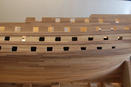
The pictures below show very well how I proceeded. These also show that I made enthusiastic use of the gun ports to hook in my glue clamps. There would be a lot more of this later when completing the 2e planking below the waterline

View attachment 499533

View attachment 499534

After completing the planking all the way to the waterline, I scraped the surface lies. Such that it is not perfectly smooth. With this, I tried to approach the situation as I think it was before. The intention was thus to leave some unevenness visible in the planks. I hoped this would be reflected later after the hull is painted.
The following photos gives a good idea of the final result above the waterline.

View attachment 499535

View attachment 499536

Earlier, I indicated that I wanted to follow Petr's method below the waterline. This would mean that I would have to divide the distances across all bulkheads from the existing planking to the keel by 32 planks everywhere. When I calculated this and drew the results on the hull, this clearly gave problems with this model at the bow and stem. This can be clearly seen by the lines that stop suddenly on the hull. These curves cannot be made without huge horizontal stresses in the planks.

View attachment 499537

View attachment 499538

I therefore chose to follow the natural curve here anyway. At the stem, I therefore had to start using stealers. Nice learning project again. In fact, a continuation of the method I followed above the waterline.

In retrospect, when planking the section above the waterline, I already made an essential mistake by not following the rules for planking an English ship. By following the natural bending of the planks, I started rejointing too early. In reality, rejointing only starts below the lower wale.
However, you have to learn from your mistakes people often say, but from my mistakes others can also learn. That is also the motto of this forum. That is why I have tried to analyse things to see what went right and what did not. An extensive analysis can be seen in my Dutch construction report https://www.modelbouwforum.nl/threads/hms-victory-van-caldercraft-door-wil.281364/page-7

My conclusion at the time:
If I want to do it completely according to the rules, I will have to take off the entire 2e planking, which I have applied so far, and start with the lower wale, of thicker material. However, this is going way too far for me.
Three quarters of the hull will soon be covered in paint or copper. I want to leave the last quarter (one side below the waterline) transparent without copper for now. Here I want to show what I have to offer as a modeller, rather than following the official planking pattern. Applying tapered boards and stealers nice and tight was hard enough.

Meanwhile, I had managed to spend quite a few hours on my Victory again. The second planking is almost halfway done. I managed to keep things straight and the lines of the planks flowing quite nicely. It took me about an hour on average to get one plank on from bow to stern. Total 64 to go, of which 24 were done at that point. I am satisfied with my choice to continue my way, although I would have loved to compete with the other method. But fortunately, it is not a competition. The pictures below give a nice result so far.

View attachment 499539

View attachment 499540

View attachment 499541

After few more days of hard work on the 2e planking, this project is now complete. After the glue hardened, I lightly scraped the planking. Below is an impression of what it has become.

View attachment 499542

View attachment 499543

View attachment 499544

As I mentioned, I wanted to copper plating my ship below the waterline on one side and finish the other side transparently, I think with danish oil. The question of which side and how, hung in the air for a while. Of course, the prettiest side had to be oiled. However, the answer to this question came sooner than I thought. When scraping the last piece of the 2e planking, I actually got through the walnut. Needless to say, this side was going to be coppered.
Beautiful work and very detailed and useful explanations.
Excellent
 
08 Wales

The next step in my project was to fit the wales.
The dimensions were easy to deduce from their position relative to the gun ports on the construction drawing.

The lower wale is constructed from 2 strips of 10 mm walnut of 1 mm (topp and butt system), with a walnut strip of 4x0.5mm above. However, the building description assumes 4 slats of 5x1 mm, so I had to buy additional slats of 10 mm. In the end, I ended up with slats of 105 mm, with the top at 1/3 of the length. The widest part will be 6.5 mm, the narrowest part 3.5 mm. For the mould I'm going to use wide saw blades.

The centre wale is 10.5mm wide of walnut 1mm (anchor stock system). However, the building description assumes 3 slats of 3.5x1mm, so I had to buy 10mm slats for this too. In the end, I ended up with 70mm slats, with the top in the middle. The widest part will be 6.75 mm, the narrowest part 3.75 mm.

The upper wale will be a continuous strip 10x1mm.

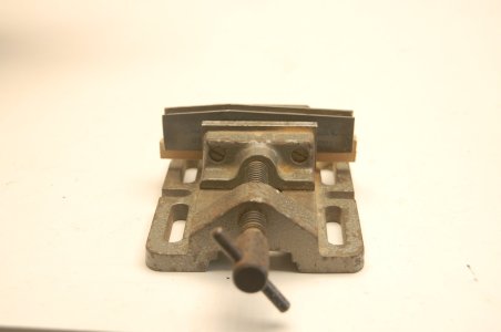
First, from an old saw blade, I ground the moulds for the topp and butt system and the anchor stock system. With a wooden batten at the bottom, I glued the two steel mould halves into my small bench vice, this way I will soon be able to plane and sand 8 slats simultaneously into their shape.

DSC_4222.JPG

Next, on the starboard side, the lines were drawn for the lower gunwale. First, using the blueprint, I set out the dimensions in relation to the gun ports and then used a slat and nails to make a stop for the lower topp and butt strip in a flowing line. The section between the forward gun port and the keel was the trickiest. After making some minor corrections here and there, I think this should be it. The short pieces of slat mark the lower topp and butt strip

DSC_4220.JPG

First, cut a quantity of slats and plane and sand them into shape in the mould made. Each layer consists of 9 laths of 105 mm, times 4 layers per side makes 72 pieces. Then break the edges of the slats on one side, creating 50% left-handed pieces and 50% right-handed pieces. This is due to the fact that the pattern of the bottom half of the two topp and butt strips is opposite to the top half.

Then the application could begin. Coat the batten with glue, press it down and immediately remove excess glue. Then use button pins to keep the slat in place. Wet where necessary and bend warm. This way, it was fairly easy to apply the slats.

Initially on the starboard side, made the mistake of keeping the bottom and top layers parallel, creating two seams in one place. So one half scrapped again.

DSC_4232.JPG

Secondly, staggered the two patterns by 17.5 mm to create a more solid balance. In some places, however, some height differences crept into the laths, these sanded away. I deliberately did not do this completely smooth, as this will certainly not be the case in real life. Next, I filed down the details with a fine file, which a) removed excess glue residue and b) revealed an even joint pattern everywhere.

Finally, on top of the wale, glued a slat of 4x0.5 mm.

DSC_4245.JPG

The middle wales are fitted using the same principle as the lower ones, but using the anchor stock system. The upper wale consists of a completely continuous batten, on which I applied fake seams. The photos below speak for themselves, I think.

DSC_4250.JPG

 
I'm working on a much older (25+ years) at this time. I think you are doing terrific.

By the book planking seems Soooooo complicated to me. As crude as this might sound, when processing a fish I know what I want in the end and how I get there doesn't matter a lot. :cool:
 
Excellent work, but for the future model, know that the sheathing lines did not intersect. They all went parallel, since there was no lower and upper layer. The thicker one was like a regular board and went parallel to the others, it was just thicker. Also, the openings for the gun ports are a little big, but not critical. But still, you have good progress.Screenshot_20250210_084814_Gallery.jpg
I implemented my casing in a similar way, but a little differently. If you are interested, you can take a look.
 
Last edited:
Sergey, you are right, I made a wrong choise whit my second planking. Caldercraft put the Wales on the second planking and not between the planks. Anyway I choose for the simpel way, but nog the right one. Good for my future model.
 
I love that you drew in the bands and did not plank with strakes ending in a point short of the rabbet. :) One thing that most, if not all, kits get wrong are ignoring the tapering of the thickness of the wales. They seat in the rabbet, same as all the other planks. That means the thickness has to be reduced to match the other planking so it does not stand proud and can be seated as they should. Further to Serikoff's comment on the gun ports, the first photo he posted shows port lid stops (linings) inside the top of the ports which was not done, at least not on British warships. There were stops on the sides and bottom only.
Allan
By the way, I made the belts narrow towards the bow and the tail of the ship. And to be precise, the port frame was on the sides and TOP)))) But I did it according to Evgeny Epur's model. And if I were to do it now, I would do it as it should be. But this is not a big mistake, it does not greatly affect the appearance.Screenshot_20250212_233434_Gallery.jpg
 
I would do it as it should be. But this is not a big mistake, it does not greatly affect the appearance.
Whatever makes us happy is exactly what our hobby is about. :) :) I agree with you that most folks would not notice. The only reason I am aware of it at all is after it was pointed out to me by David Antscherl when he saw one of my early models and I did the port linings incorrectly having a top lining. Ed Tosti and I also had the privilege to tour Preble Hall togther with Grant Walker who confirmed this when we were studying their models for these kinds of details. I thoroughly trust their research and experience.
Allan
 
09 The deck planking of the middle gun deck

I had addressed Jotika about what I consider to be the very poor quality of the slats for the deck planking. I think it is tanganjika wood. The edges of the slats are very rough, many strips are warped and the width varies from 3 to 4.2 mm. More than 50% are unusable in this way.
Jotika has indicated that it will send a new package of slats. These have subsequently been incorporated into the decks.

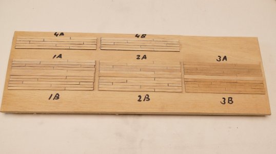
As I was waiting for a shipment of new wood from England, I had in between done some trials with stirrers, all of which I first narrowed down to 4 mm. I don't know exactly what type of wood it is, but it doesn't look like beech to me. I also did some trials with the slats already supplied.
For some of the trials, I used a 6B pencil for the caulking seams, but maybe that's too soft. It ended up being a drab. Another part I did with an Edding marker.

P1300240.JPG

I was still not satisfied with the result, probably because the pencil used then was too soft. In the end, I first broke the edges of the slats slightly and then blackened the sides with a carpenter's pencil.

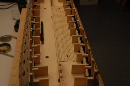
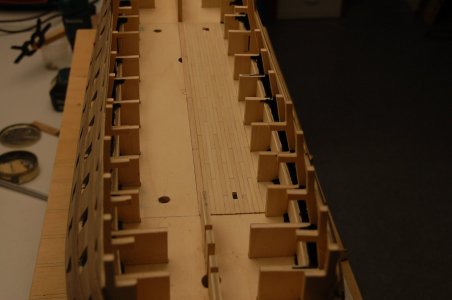
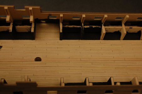
I started by planking the middle gun deck first. This had to be done in situ, as this deck was already part of the hull frame. After first fitting the king plank (1.5x the width of the other planks), the planking could begin. Immediately after this it looked quite nice (photo with pencil). After the glue hardened, I sanded the floor with 240, after which the seams were a lot less present (photo without pencil). It did give a nice even and calm look. By the way, the four round holes in the deck are the attachment points for the tilt mechanism.

DSC_4269.JPG

DSC_4270.JPG

Then on to the other half of the deck and the pieces at the side entrances. I wondered if I should add some more end seams at the side entrances so that this pattern also just continues. However, in terms of plank length, this would be unnecessary in practice.

DSC_4274.JPG

Also this and that painted further black because, looking through the gun ports and side entrances, a lot of bare wood would still be visible.
 
10 The gun ports

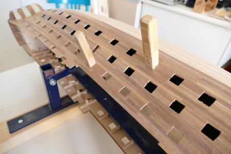
Meanwhile, work also started on finishing the gun ports. For now, first those of the lower and middle gun decks, as the penetrations of the upper gun deck and above will have to be made after the inner bulwark is fitted there.
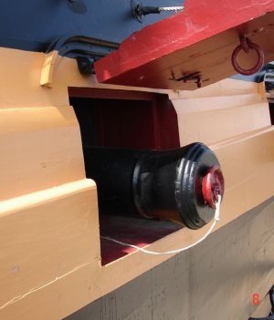
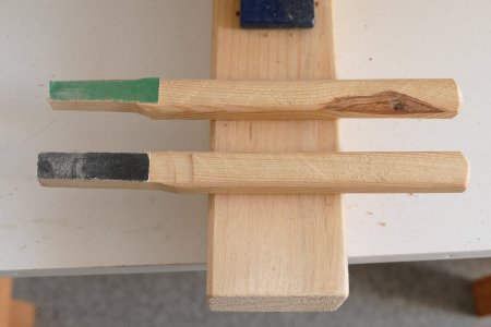
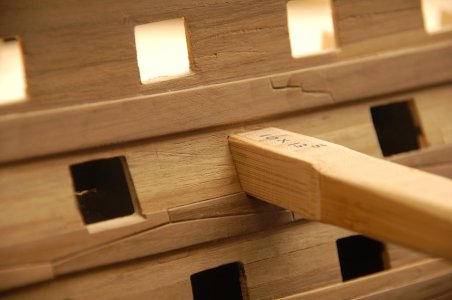
To file out the gun ports, I made two templates. This is because the bottom row of holes is half a mm longer and higher than those in the rows above it. For exact filing, I made separate sanding sticks, so I can use the right-angle and use the side without sandpaper as a guide

P1300215.JPG

P1300218.JPG

After fitting the wales, this had to start all over again, especially at the bottom, where bits had to be filed out of the wales.

DSC_4261.JPG

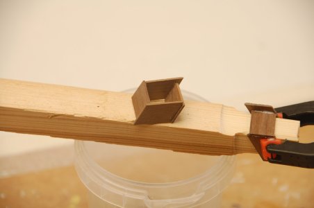
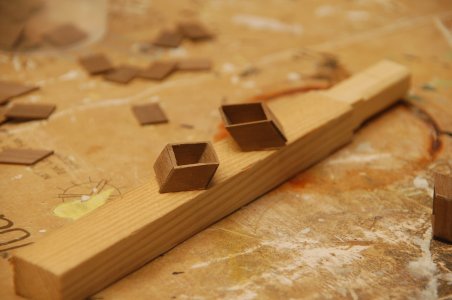
I made the lining of the gun ports from scrap pieces of 1x10 mm nuts, which I initially pottered around a template. After the glue cured, I sanded away the excess material on the outside with the disc sander.

DSC_4260.JPG

DSC_4264.JPG

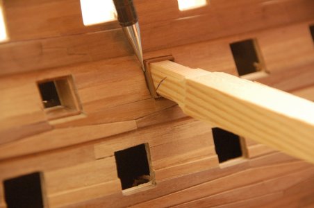
Then put the lining of the gun port on the template and fed it into the filed-out gun port. Then the pattern of the 2e lining was marked on this and sanded to size along these lines. For the right direction and slope, I use a glue clamp, against which I fix the template.

DSC_4262.JPG

DSC_4265.JPG

After sanding to size, put the covering back on the template, smeared the outside with a bit of wood glue and reintroduced it into the gun port, in such a way as to create a 1x1mm rebate all around. Then fix the mould again against the glue clamp and apply some extra glue on the inside. After curing, remove the template and Wil is ready.

Only, there are about a hundred of them. So this process took a while for me to complete. So nice stop work during the various project sections.

It was pointed out to me by another modeller that there should be no rebate at the bottom of the gun ports. I solved this by gluing a small slat in the rebate, which was created initially. Filing and sanding well was later enough to see no more of this. I will continue to use this method of approach, as it is easier to glue in a slat later, than to let the underside of the panelling continue.

DSC_4278.JPG

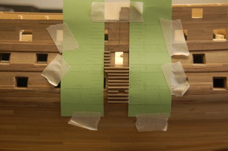
After completing the gun ports of the lower and middle gun deck, a start was made on the two outer stairs. You can see from the photos that there are still some scratches here and there, which need to be touched up. But that will come later, when I start painting. Also, there are a number of seams in the wales that may be a bit too rough, I think. But we'll tackle that right away, too.

I had chosen to do all the exterior gluing work on bare wood. Hence, I have already made the exterior stairs on it at this stage. This will also apply to fitting the rests later. But this can only be done once the upper gun deck has been fitted and the corresponding gun ports lined.

For dividing the stair treads and finding logical places between the storage bolts, I made a template, so the treads will sit nice and straight on them later.

DSC_4277.JPG
 
Back
Top