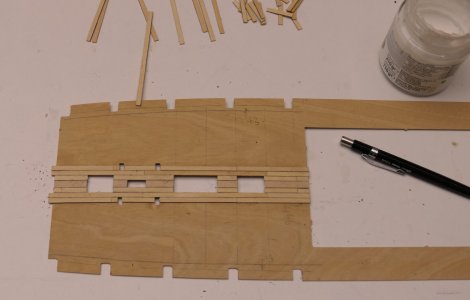
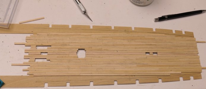
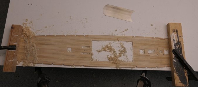
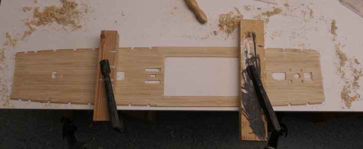
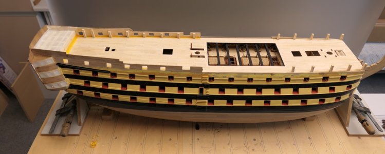
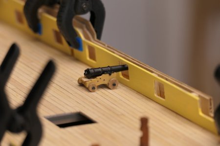
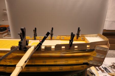
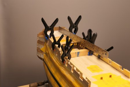
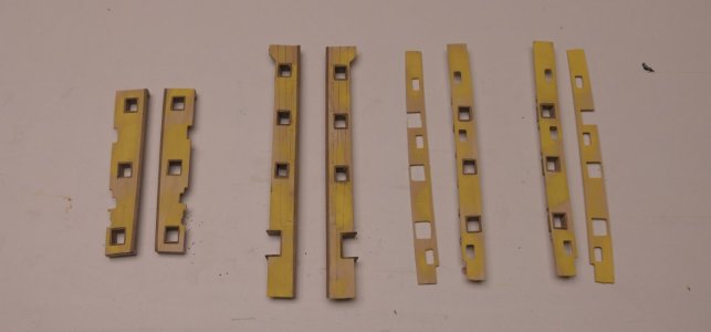
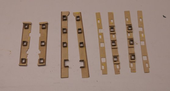
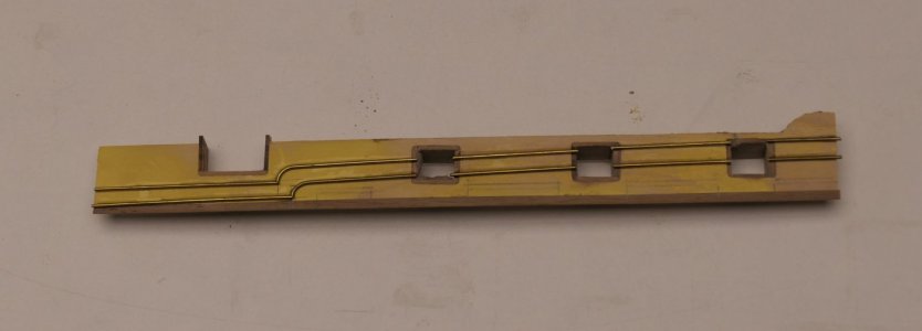
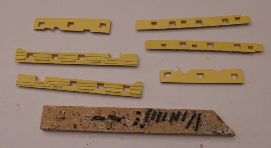
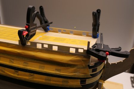
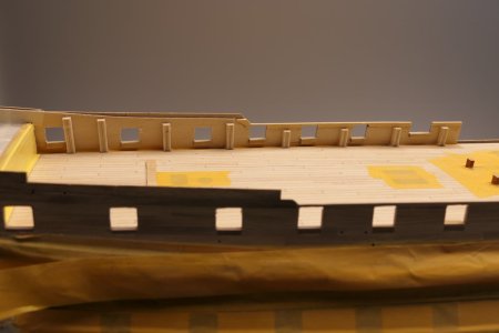
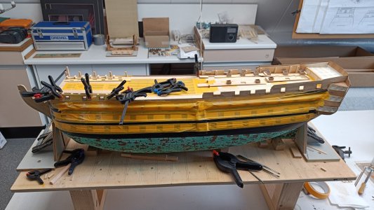
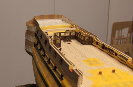
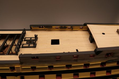
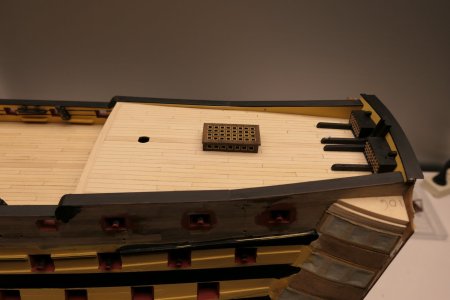
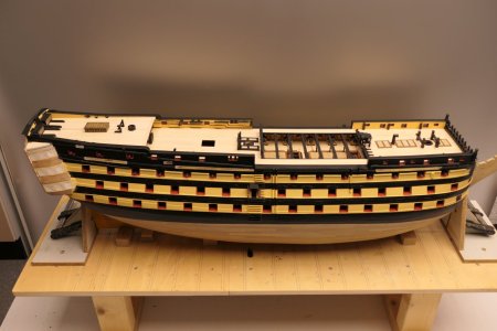
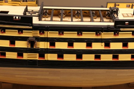
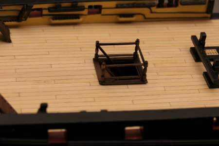
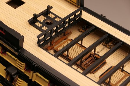
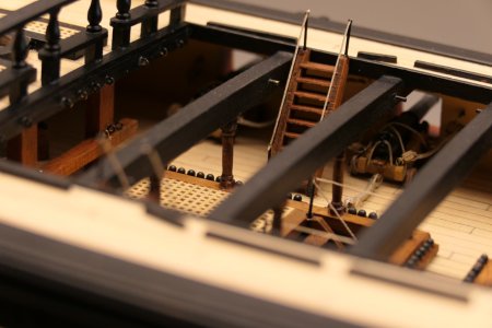
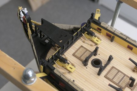
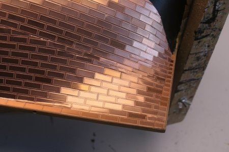
HMS Victory of Caldercraft by Wil

15 Coppering part 1

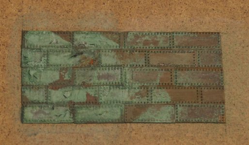
Before we left for England on 6 June 2023 to visit the Victory, I had deployed a test for ageing the copper plates, called patination. You can do this with a mixture of ammonia, vinegar and salt. Initially, the process was slow and the result was very different on the various plates. Then I had abandoned the trial a bit and let time do its work. Well aged they were, even so much so that some of the platelets dissolved.
I imagine there will be modellers among us who will get a kick out of this, but not me particularly. Regardless of how this will work in practice with so many plates, I didn't like it at all, this look.
Results below. Everyone can think what they like about it.
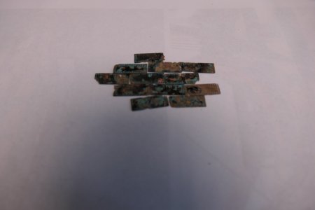
P1010915.JPG

After returning from England, I decided to take the gamble after the patination trial and age the entire quantity of copper plates for one side. Since I didn't have ammonia in the house, they first spent a few days in a mixture of vinegar and table salt. Very slowly, after about four days, I started to see some changes to the plates, but it was slow going. A few days later the ammonia was in the house and I did a dash of it. A day later, to my surprise, I saw that the process had accelerated. The entire liquid had turned bright blue and the plates started to clump together. Quickly took everything out and rinsed/washed well with clean water. And aged they were. At the moment, they are drying. See the results below.
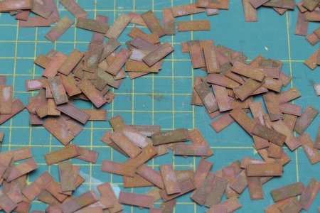
P1010939.JPG

As time passed, however, the look of the patination process became more unsettled than I had hoped. When I took the previous photos of the patination process, the plates were probably not completely dry yet. By now they are, and I feel that the process of ageing is still continuing at this point.

After a while, the time had come, the coppering could begin.
In short: I started with a slat under the top row of plates.
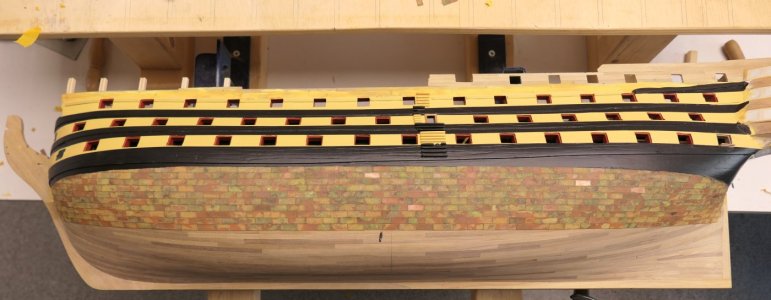
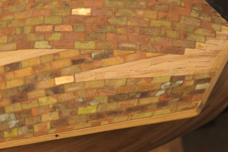
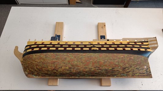
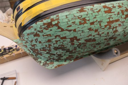
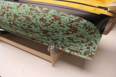
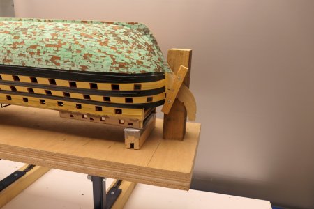
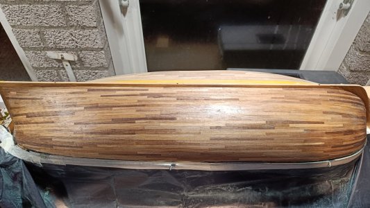
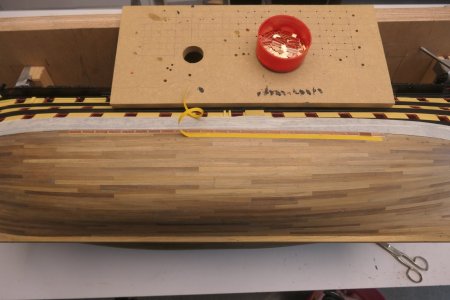
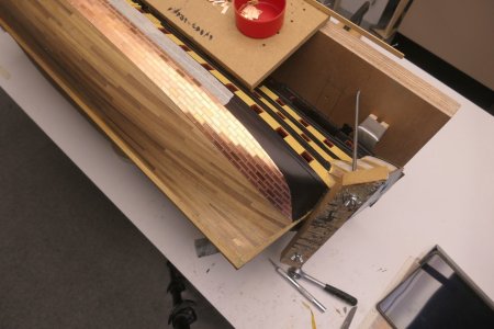
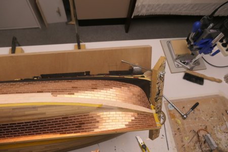
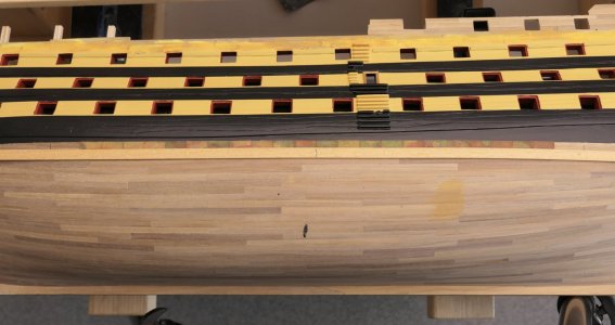
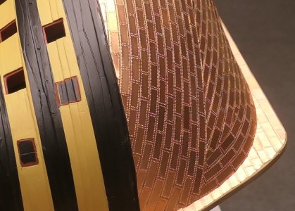
Then a strip of double-sided adhesive tape on it, 6mm wide, roughly up to the 4e gun port from fore and aft, from the centre 11 plates to the left and 11 to the right. When there are 7 rows on it in half-brick a batten below that deflects to the intersection of the waterline with the bow and stern. Then lay the 7e row to these intersection points and seal the sections above with plates. When these two points are completely closed, continue along the 7e row with the 8e to the 12e row. The lower section starts against the keel and is only cut against the first section.
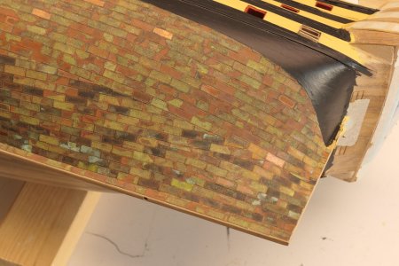
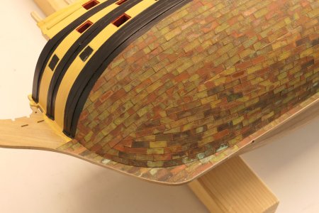
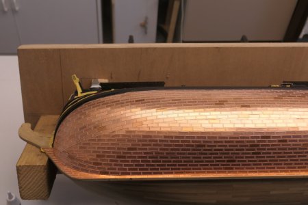
The pictures below speak for themselves, I think.
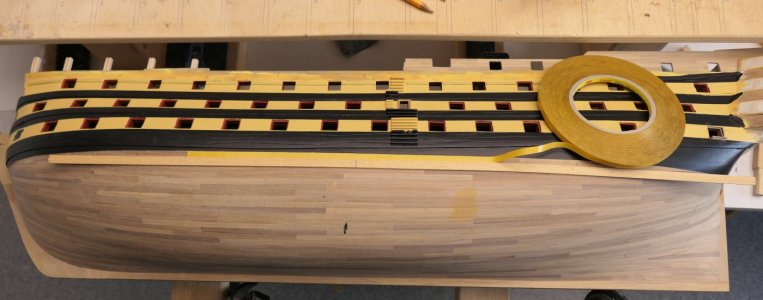
P1010941.JPG

P1010943.JPG

P1010946.JPG

P1010951.JPG

I admit, it takes some getting used to. The pictures were taken from above with the boat on its side. I am curious to know what you guys think. At least I was satisfied at that point.

After completing the first 12 rows from the waterline, I started against the keel. First I covered the keel, so that the plates on the hull fall over this and you don't see a seam. I kept the plates on the keel a mm back along the edges, so the plates won't get caught everywhere later. This edge and the ends of the keel were later treated with clear varnish.

At the rear, I still had to use a stealer to get the plates on the fuselage somewhat in smooth lines.

P1020965.JPG

P1020968.JPG

P1020970.JPG

The last rows of plating all zero off against the 12e row from the top. In the middle section, the plating is closed over about half a length with half-width plates.

Resuming:
  • Applying the plates did not disappoint me at all. Actually done in no time at all.
  • I marked the plates with a scriber, after which they could be cut neatly straight with the self-made "guillotine". Cutting with an old pair of kitchen scissors also works well, but then the plates quickly warp.
  • Gluing with the double-sided tape is a godsend. I didn't have the impression that the patination was bad for the adhesion to the tape. The stuff sticks just fine, but the biggest advantage is that the glue joint remains flexible so that something can always be corrected. This is in contrast to superglue. The plates stay nice and clean. No glue remains. And the plates stick over the entire surface.
However, the patination itself was an entirely different story.
As I mentioned earlier, I was actually caught off guard by an acceleration in the chemical reaction with the first batch of plates (1 full bag of the 2 provided). This created the variegated colour palette. When I had the first 12 rows on, I began to have some doubts about whether 1 bag would be enough for one side. So no, or maybe if you have no waste at all.
So then started the patination process with a second batch. This went slowly and when I saw that the plates had all turned dark brown, I quickly removed them from the chemical bath and rinsed them off. The result was beautiful, but the plates were still wet.

At that point, I seriously considered removing the already applied plates and starting over. But when the plates were dry, the result turned out to be disappointing anyway, they had become even more furry.
In the end, I mixed both sides. You can see the result in the picture below. Despite this setback, I am still satisfied with the final result.

IMG20230718151136.jpg

Patination kept me pretty busy over the following weeks. As it turned out, it was still a living process. I will use some photos to show you what happened.
The last photo was the situation immediately after the coping was completed, on 18 July.

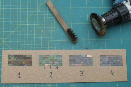
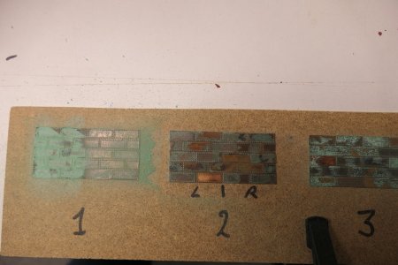
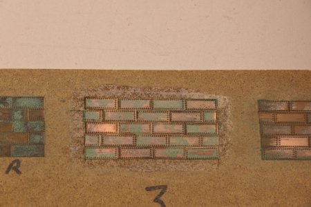
Since the variegated result still kept me busy, I made a small test piece on 27 July, to which I applied a number of edits. See photo below.

P1020975.JPG

In detail 1, the plates are untreated, so as they are on the ship.
For detail 2, I applied a layer of varnish to insulate the panels and fix the seams somewhat.
Detail 3 shows an edit of a light treatment with a small brass brush
Detail 4 is the result after I used the round brass toll to brush the plates very lightly and briefly.

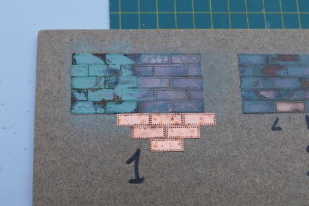
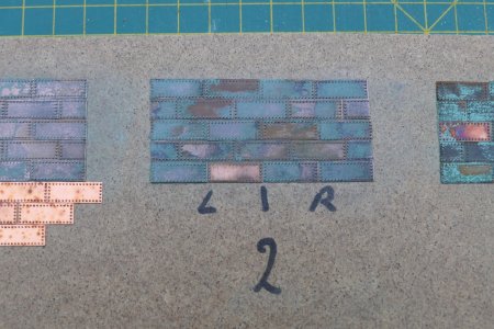
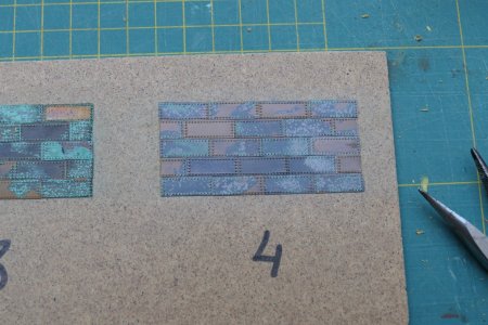
On 6 August, the trial plate result was as shown in the photos below. The plates on the hull are also clearly changing.

P1020982.JPG

My preliminary conclusion at the time was as follows:
Test piece 1: where there was some kind of tarnish on the plates, it changes to a green layer of copper oxide. This process seems to continue.
Test piece 2: varnishing has an adverse effect on the appearance. A milky-white-like layer remains on some plates, which is not nice.
Test piece 3: here were initially scratches, which are clearly fading in a later phase.
Sample 4: This treatment gives a much calmer look and is the least subject to change. At the moment, hardly any difference is noticeable. The shiny does come off a little.
During the patination process, a kind of deposit apparently formed on the plates, accelerating the ageing process. If you remove this deposit by brushing, you slow down this process again. At the moment, I was tempted to brush the copper plates with the spinning top, as in test piece 4, but that can always be done.

The expectation was that discolouration in practice would bring about a more even image.
If this were to continue with me, the plates might soon turn completely green. Then I will get close.
Problem then became, "How do I get this process stopped, otherwise all the plates will soon perish?"
The varnish layer is of water-based varnish. Beneath the varnish layer, the process also continues and the pictures turn greener and greener.

For now, just wait and see what happens next.
 
I understand that you have all become a bit quiet from my previous post about coppering. But don't panic, there will be a new post soon. So let's quickly move on to the next chapter.

16 Talies and troot brails

With the fitting out of the upper gun deck in process, the time was also approaching when I had to start working on the first ropework, namely the troot brails and the talons of the guns. I must say that it does take quite a switch to this fine tinkering with those ropes and smallest pulleys.

For the talies, I proceeded as follows:
Fixed pulley (comes against the side wall of the vessel, where the overtaking rope starts)
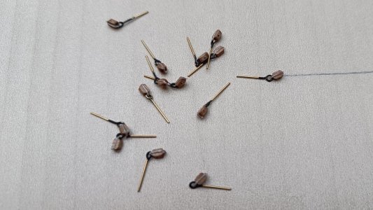
  • First glue the rope to the pulley on one side. Then attach a screw eye and, with some space, glue the rope to the other side of the pulley.
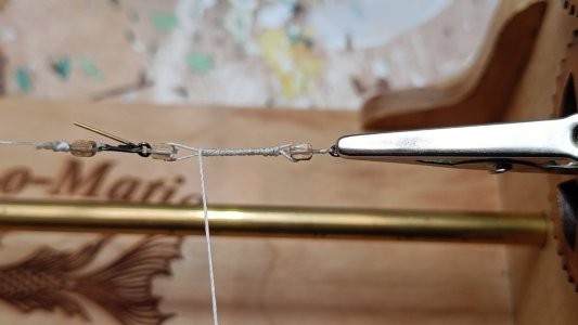
  • Next comes the wrapping machine "Serv-o-Matic", which I bought in America. In the winding machine, I have mounted a crocodile-mouth clamp on the left and right, which is used to tension the workpiece. On the right side, the screw eye is clamped in this clamp and on the other side of the pulley I fix the workpiece with a medical clamp. Then it becomes a matter of turning several turns, so that the portions of the rope are twisted to the left and right of the pulley. Once the pulley is twisted nice and tight in the rope, apply a bit of super glue with a toothpick and let it dry.
IMG20230812113615.jpg

IMG20230813164433.jpg

Loose pulley (enters the roller horse at the back, through which the overtaking rope must pass)

  • The first step is the same as for the fixed pulley, except that no space is kept in the rope so that the screw eye is tight against the pulley.
  • Once the rope is glued to the pulley on two sides, I place a knot against the pulley and glue it in place. I use diluted PVA glue (50/50) for this.
IMG20230813094236.jpg

Assembly:
  • The rope from the fixed pulley then passes through the loose pulley and then through the fixed pulley.
  • The correct length of the talie, in my case 27 mm from eye to eye, is fixed with some PVA glue
  • This assembly is then stretched back into the wrapping machine, after which the remaining rope is gently twisted around the talie. PVA glue on top and ready for mounting in the ship.
  • Afterwards, it was pointed out to me that I had mounted the blocks the wrong way round on one section. I left this as it was. I used the wrong talies on the upper gun deck. Nobody sees it.

The troot brail is a different story

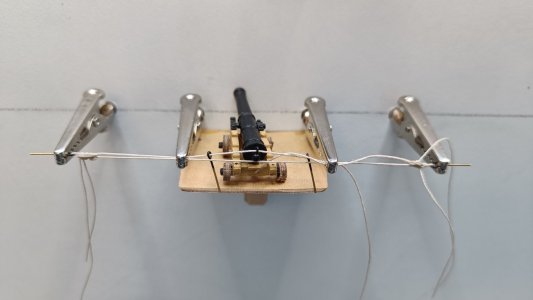
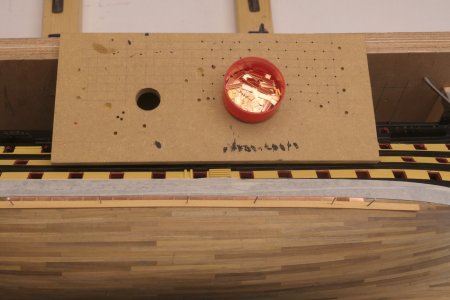
For the cannons on the upper gun deck, in my case, the broach needs to be 98 mm long, measured between the two eyes that go into the inner entrenchment. The problem with this is that in one work step, the gun and the two eyes, which go into the roll horse on either side, have to be assembled immediately.
For this purpose, I drilled four alligator clip clamps in a vertical board, with the distance between the two outer clamps being 98 mm.
The middle two clamps serve to tightly fix the loose thread on both sides to then complete the knot on the left and right at the outer clamps. The picture below is the first broaching of the whole set. The knot is not yet ideal, but that will improve as we go along, I think.
Between the two middle clamps I mounted a platform, on which the gun can stand during this process.
Once everything is in place, the knots are smeared with diluted PVA glue. After curing, the loose ends are cut off and Wil is ready.
As a of large part of the guns will not be visible later, I decided to only rig up 8 guns on either side completely. So for now, 15 sets to go for this deck.

IMG20230814162946.jpg

I kept the thickness of the rope, as mentioned in the building description - 0.25 mm for the talies and 0.5 mm for the broaching. At a scale of 1:72, that would mean 36 mm in reality, but it looks a bit thin. For the guns that will soon be in full view, I will pay closer attention to this.

P1021012.JPG

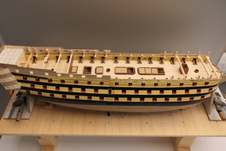
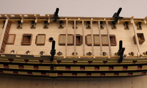
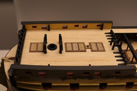
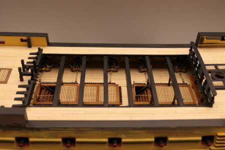
Now that the guns are basically all done and in place, the layout of the upper gun deck can begin. With the gratings and bulkhead and stairs to the middle gun deck on it, it immediately becomes a very different picture. A more complete ship, shall we say.
The guns are also nicely aligned and lined up on the outside.

P1021024.JPG

What I am still contemplating is fitting the catchallies. For this, I first want to do a test with the extremely small and thin screw eyes that are supplied. I want to make hooks from these. To be continued
 
08 Wales

The next step in my project was to fit the wales.
The dimensions were easy to deduce from their position relative to the gun ports on the construction drawing.

The lower wale is constructed from 2 strips of 10 mm walnut of 1 mm (topp and butt system), with a walnut strip of 4x0.5mm above. However, the building description assumes 4 slats of 5x1 mm, so I had to buy additional slats of 10 mm. In the end, I ended up with slats of 105 mm, with the top at 1/3 of the length. The widest part will be 6.5 mm, the narrowest part 3.5 mm. For the mould I'm going to use wide saw blades.

The centre wale is 10.5mm wide of walnut 1mm (anchor stock system). However, the building description assumes 3 slats of 3.5x1mm, so I had to buy 10mm slats for this too. In the end, I ended up with 70mm slats, with the top in the middle. The widest part will be 6.75 mm, the narrowest part 3.75 mm.

The upper wale will be a continuous strip 10x1mm.

First, from an old saw blade, I ground the moulds for the topp and butt system and the anchor stock system. With a wooden batten at the bottom, I glued the two steel mould halves into my small bench vice, this way I will soon be able to plane and sand 8 slats simultaneously into their shape.

View attachment 500418

Next, on the starboard side, the lines were drawn for the lower gunwale. First, using the blueprint, I set out the dimensions in relation to the gun ports and then used a slat and nails to make a stop for the lower topp and butt strip in a flowing line. The section between the forward gun port and the keel was the trickiest. After making some minor corrections here and there, I think this should be it. The short pieces of slat mark the lower topp and butt strip

View attachment 500419

First, cut a quantity of slats and plane and sand them into shape in the mould made. Each layer consists of 9 laths of 105 mm, times 4 layers per side makes 72 pieces. Then break the edges of the slats on one side, creating 50% left-handed pieces and 50% right-handed pieces. This is due to the fact that the pattern of the bottom half of the two topp and butt strips is opposite to the top half.

Then the application could begin. Coat the batten with glue, press it down and immediately remove excess glue. Then use button pins to keep the slat in place. Wet where necessary and bend warm. This way, it was fairly easy to apply the slats.

Initially on the starboard side, made the mistake of keeping the bottom and top layers parallel, creating two seams in one place. So one half scrapped again.

View attachment 500420

Secondly, staggered the two patterns by 17.5 mm to create a more solid balance. In some places, however, some height differences crept into the laths, these sanded away. I deliberately did not do this completely smooth, as this will certainly not be the case in real life. Next, I filed down the details with a fine file, which a) removed excess glue residue and b) revealed an even joint pattern everywhere.

Finally, on top of the wale, glued a slat of 4x0.5 mm.

View attachment 500421

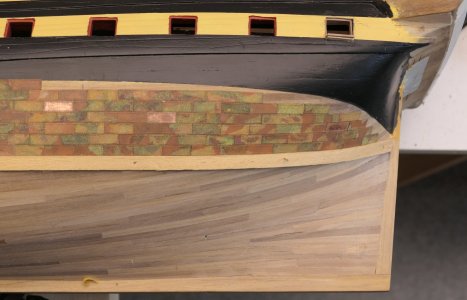
The middle wales are fitted using the same principle as the lower ones, but using the anchor stock system. The upper wale consists of a completely continuous batten, on which I applied fake seams. The photos below speak for themselves, I think.
View attachment 500422

Sorry but Ive just caught up with being able to make a comment here. This is a great model. The lower wales here, in my opinion, are just fantastic. This is something I want to do on mine as I know this is how the wales were done. These wales are engraved on the tooling on the Heller 1/100 Victory hull too. May I use, the dimensions for the lower and middle wales that you calculated please? I've just got to put them on my beast. When I bought the kit it was my intention to do this but its great to see other people doing the same thing too. Just looking for a way to create a template tool so I can mill them to shape.
Thanks & cheers
 
I understand that you have all become a bit quiet from my previous post about coppering. But don't panic, there will be a new post soon. So let's quickly move on to the next chapter.

16 Talies and troot brails

With the fitting out of the upper gun deck in process, the time was also approaching when I had to start working on the first ropework, namely the troot brails and the talons of the guns. I must say that it does take quite a switch to this fine tinkering with those ropes and smallest pulleys.

For the talies, I proceeded as follows:
Fixed pulley (comes against the side wall of the vessel, where the overtaking rope starts)
  • First glue the rope to the pulley on one side. Then attach a screw eye and, with some space, glue the rope to the other side of the pulley.
  • Next comes the wrapping machine "Serv-o-Matic", which I bought in America. In the winding machine, I have mounted a crocodile-mouth clamp on the left and right, which is used to tension the workpiece. On the right side, the screw eye is clamped in this clamp and on the other side of the pulley I fix the workpiece with a medical clamp. Then it becomes a matter of turning several turns, so that the portions of the rope are twisted to the left and right of the pulley. Once the pulley is twisted nice and tight in the rope, apply a bit of super glue with a toothpick and let it dry.
View attachment 511057

View attachment 511058

Loose pulley (enters the roller horse at the back, through which the overtaking rope must pass)

  • The first step is the same as for the fixed pulley, except that no space is kept in the rope so that the screw eye is tight against the pulley.
  • Once the rope is glued to the pulley on two sides, I place a knot against the pulley and glue it in place. I use diluted PVA glue (50/50) for this.
View attachment 511059

Assembly:
  • The rope from the fixed pulley then passes through the loose pulley and then through the fixed pulley.
  • The correct length of the talie, in my case 27 mm from eye to eye, is fixed with some PVA glue
  • This assembly is then stretched back into the wrapping machine, after which the remaining rope is gently twisted around the talie. PVA glue on top and ready for mounting in the ship.
  • Afterwards, it was pointed out to me that I had mounted the blocks the wrong way round on one section. I left this as it was. I used the wrong talies on the upper gun deck. Nobody sees it.
The troot brail is a different story

For the cannons on the upper gun deck, in my case, the broach needs to be 98 mm long, measured between the two eyes that go into the inner entrenchment. The problem with this is that in one work step, the gun and the two eyes, which go into the roll horse on either side, have to be assembled immediately.
For this purpose, I drilled four alligator clip clamps in a vertical board, with the distance between the two outer clamps being 98 mm.
The middle two clamps serve to tightly fix the loose thread on both sides to then complete the knot on the left and right at the outer clamps. The picture below is the first broaching of the whole set. The knot is not yet ideal, but that will improve as we go along, I think.
Between the two middle clamps I mounted a platform, on which the gun can stand during this process.
Once everything is in place, the knots are smeared with diluted PVA glue. After curing, the loose ends are cut off and Wil is ready.
As a of large part of the guns will not be visible later, I decided to only rig up 8 guns on either side completely. So for now, 15 sets to go for this deck.

View attachment 511061

I kept the thickness of the rope, as mentioned in the building description - 0.25 mm for the talies and 0.5 mm for the broaching. At a scale of 1:72, that would mean 36 mm in reality, but it looks a bit thin. For the guns that will soon be in full view, I will pay closer attention to this.

View attachment 511062

Now that the guns are basically all done and in place, the layout of the upper gun deck can begin. With the gratings and bulkhead and stairs to the middle gun deck on it, it immediately becomes a very different picture. A more complete ship, shall we say.
The guns are also nicely aligned and lined up on the outside.

View attachment 511063

What I am still contemplating is fitting the catchallies. For this, I first want to do a test with the extremely small and thin screw eyes that are supplied. I want to make hooks from these. To be continued
Looks amazing. I love the last picture showing all her cannons in line .
 
Sorry but Ive just caught up with being able to make a comment here. This is a great model. The lower wales here, in my opinion, are just fantastic. This is something I want to do on mine as I know this is how the wales were done. These wales are engraved on the tooling on the Heller 1/100 Victory hull too. May I use, the dimensions for the lower and middle wales that you calculated please? I've just got to put them on my beast. When I bought the kit it was my intention to do this but its great to see other people doing the same thing too. Just looking for a way to create a template tool so I can mill them to shape.

Thanks & cheers
The lower wale is constructed from 2 strips of 10 mm walnut of 1 mm (topp and butt system), with a walnut strip of 4x0.5mm above. However, the building description assumes 4 slats of 5x1 mm, so I had to buy additional slats of 10 mm. In the end, I ended up with slats of 105 mm, with the top at 1/3 of the length. The widest part will be 6.5 mm, the narrowest part 3.5 mm. For the mould I'm going to use wide saw blades.

The centre wale is 10.5mm wide of walnut 1mm (anchor stock system). However, the building description assumes 3 slats of 3.5x1mm, so I had to buy 10mm slats for this too. In the end, I ended up with 70mm slats, with the top in the middle. The widest part will be 6.75 mm, the narrowest part 3.75 mm.

The upper wale will be a continuous strip 10x1mm.

Thanks for following me.
Thankyou
 
17 The quarterdeck

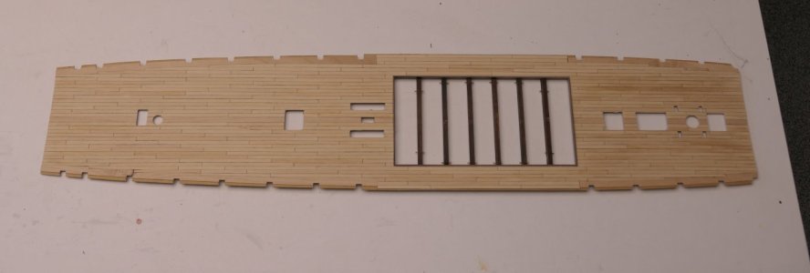
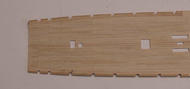
I made the quarterdeck waterway plank slightly narrower than on the upper gun deck. Eventually, the laying pattern of the deck planks will determine the final width when joggling begins.

P1021544.JPG

Back in time for a moment:
When fitting the plywood panels against the outer wall (first planking), it was a matter of finding the right fit, this and that in relation to the embrasures and the inner bulwark(s). Of course, this is not a one-to-one fit and concessions have to be made here and there to the drawings and dimensions. Important here, for example, is the optical result of the aligned guns. Of course there are adjustment wedges under these, but that's not all. Especially if all guns later have to come out of the embrasures at the same height and also all have to be virtually level.
Anyway, long story short: when aligning the upper gun deck at the rear, I had to lift the deck a bit to get the right lines.
This does mean that these corrections have to be taken to the higher decks. No problem.

How do I come up with this story?
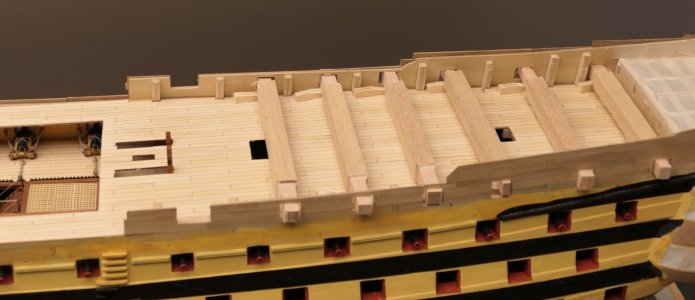
This is because of the skid beams. Unlike the camber beams, the skid beams are not mounted against the bulkheads, but have to be mounted against the underside of the quarterdeck, resting on the wooden pillars on the upper gun deck. All in all, not really convenient this way. The skidbeams was one of those things that has kept me busy for weeks, especially the wooden pillars underneath. How do I get that together properly.
My first idea was to make some kind of rackwork. I glued the pillars against the underside of the skidbeams. The glued joints were all a bit fragile, but that's probably because of the stain I had on the parts by now.

P1021030.JPG

Anyway, by now the quarterdeck is ready for final assembly. Columns were removed from the skidbeams again and I dryfit the skidbeams with their final frames into the deck. I then tried to lay the deck back into the ship and it worked wonderfully well. This and that, the deck withstood the necessary deformations of the deck during application quite well. I have postponed the problem of the pillars for a while. My idea is to install them later from above between the skidbeams and the upper canon deck. Will be pin netting, I fear.

P1021548.JPG

Meanwhile, I was also busy planking the quarterdeck. This deck had to come in and out a number of times, so my idea with those fragile columns started to look more and more questionable deliver. Let me take you briefly through the steps I made in doing this.
Of course, I had already done some practice work on it with the upper gun deck. I took these experiences to the quarterdeck.

The main areas of focus are:
  • The quarterdeck must be fitted in one piece, unlike the upper gun deck, which is made in two halves;
  • The water walkway needs to be made a bit narrower;
  • The whole thing has to look even nicer than the upper gun deck, as a large part will remain clearly visible later. So attention to detail.
P1021029.JPG

In between business, I made a few hundred deck boards. Trimmed to 95 mm and blackened on the long sides with a carpenter's pencil. A rather dull job that I therefore did in many pieces. End edges are not blackened!

The laying pattern was done according to the 4-plank principle, taking care that starboard and port sides remain mirror images of each other. For the middle strips, take care to maintain the seam pattern because that is where the necessary openings in the deck are.

P1021526.JPG

P1021529.JPG

I first did the bow up to the pit and then the stern, until I reached the edges of the pit. Careful attention must be paid here to ensure that the pattern of the planking continues correctly later, when along the edges of the codend the planking continues along the entire length of the ship.

Initially, as many whole planks as possible are laid up to the prefabricated waterloop plank. I fixed this watercourse plank to the deck with a few pieces of double-sided plan tape.

Then the jogging begins. Hereby the following rules of play:
  • Plank ends never narrower than half a plank width;
  • Find the point where a board can no longer hold its full width against the watercourse board;
  • From this point, rejuvenate the plank to half a plank width;
  • Above all, make sure port and starboard stay parallel;
  • Don't worry too much about the mess created when gluing the boards. Better a little too much glue than too little. Meanwhile, you will also have to clean your hands several times because your fingers will get too thick.
Then in the picture below is the rough overall result.

P1021537.JPG

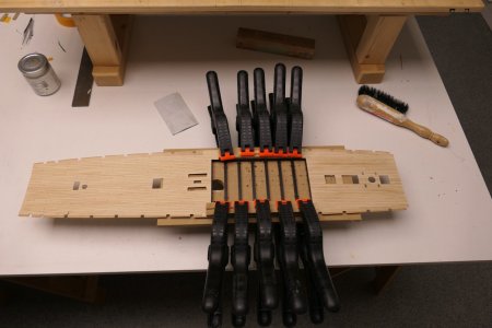
Tip: When interrupting all work on such a deck, always clamp the deck upside down against the tabletop afterwards, to prevent warping (hollow in this case) as much as possible.

I then scraped the deck to remove all glue residue and make the deck smooth. Clamping the deck well on the table top to work firmly. First the middle piece, then both ends.

P1021539.JPG

P1021540.JPG

P1021541.JPG

Then it was the turn of the butt joints. I created these with a thin pencil (0.3 mm) by accentuating the end joints between the boards and scratching them in slightly. This involves finding a good balance in the appearance. This is because the end seams must match the longitudinal seams in terms of hardness, after the deck is sanded! A test piece is not unnecessary.

P1021543.JPG

P1021544.JPG

Then sand the deck in the longitudinal direction of the boards.

As a provisional final finish, I varnished the deck once with water-based matt clear varnish, so it won't get dirty easily in the future.

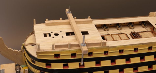
After the quarter deck had dried, the time was ripe to finally fit this deck into the model. Because the dimensions of the deck (read the correct elevation) are extremely important, something had to be thought of. You always have the deck rounding across and the deck cavity lengthwise. In addition, the exact height in relation to the gun ports.
To keep an eye on all this at the same time before the glue hardens, I came up with a few auxiliary structures as shown in the pictures below. Tested everything drifit first, of course.

P1021553.JPG

P1021554.JPG

Then, first, the framework with the skidbeams were glued into the pit recess.

P1021555.JPG

Then the deck could be inserted and glued. After curing, that looks like the photo below. As there is still a lot of filing and sanding to be done after this, I have already taped off all seams along the outer edges of the aft deck to prevent dust formation on the upper canon deck as much as possible.

P1021558.JPG

I added the columns under the skidbeams later. So I worried about this all this time for nothing. Actually, it was a piece of cake.


17 The quarterdeck

I made the quarterdeck waterway plank slightly narrower than on the upper gun deck. Eventually, the laying pattern of the deck planks will determine the final width when joggling begins.

View attachment 513192

Back in time for a moment:
When fitting the plywood panels against the outer wall (first planking), it was a matter of finding the right fit, this and that in relation to the embrasures and the inner bulwark(s). Of course, this is not a one-to-one fit and concessions have to be made here and there to the drawings and dimensions. Important here, for example, is the optical result of the aligned guns. Of course there are adjustment wedges under these, but that's not all. Especially if all guns later have to come out of the embrasures at the same height and also all have to be virtually level.
Anyway, long story short: when aligning the upper gun deck at the rear, I had to lift the deck a bit to get the right lines.
This does mean that these corrections have to be taken to the higher decks. No problem.

How do I come up with this story?
This is because of the skid beams. Unlike the camber beams, the skid beams are not mounted against the bulkheads, but have to be mounted against the underside of the quarterdeck, resting on the wooden pillars on the upper gun deck. All in all, not really convenient this way. The skidbeams was one of those things that has kept me busy for weeks, especially the wooden pillars underneath. How do I get that together properly.
My first idea was to make some kind of rackwork. I glued the pillars against the underside of the skidbeams. The glued joints were all a bit fragile, but that's probably because of the stain I had on the parts by now.

View attachment 513194

Anyway, by now the quarterdeck is ready for final assembly. Columns were removed from the skidbeams again and I dryfit the skidbeams with their final frames into the deck. I then tried to lay the deck back into the ship and it worked wonderfully well. This and that, the deck withstood the necessary deformations of the deck during application quite well. I have postponed the problem of the pillars for a while. My idea is to install them later from above between the skidbeams and the upper canon deck. Will be pin netting, I fear.

View attachment 513199

Meanwhile, I was also busy planking the quarterdeck. This deck had to come in and out a number of times, so my idea with those fragile columns started to look more and more questionable deliver. Let me take you briefly through the steps I made in doing this.
Of course, I had already done some practice work on it with the upper gun deck. I took these experiences to the quarterdeck.

The main areas of focus are:
  • The quarterdeck must be fitted in one piece, unlike the upper gun deck, which is made in two halves;
  • The water walkway needs to be made a bit narrower;
  • The whole thing has to look even nicer than the upper gun deck, as a large part will remain clearly visible later. So attention to detail.
View attachment 513201

In between business, I made a few hundred deck boards. Trimmed to 95 mm and blackened on the long sides with a carpenter's pencil. A rather dull job that I therefore did in many pieces. End edges are not blackened!

The laying pattern was done according to the 4-plank principle, taking care that starboard and port sides remain mirror images of each other. For the middle strips, take care to maintain the seam pattern because that is where the necessary openings in the deck are.

View attachment 513205

View attachment 513207

I first did the bow up to the pit and then the stern, until I reached the edges of the pit. Careful attention must be paid here to ensure that the pattern of the planking continues correctly later, when along the edges of the codend the planking continues along the entire length of the ship.

Initially, as many whole planks as possible are laid up to the prefabricated waterloop plank. I fixed this watercourse plank to the deck with a few pieces of double-sided plan tape.

Then the jogging begins. Hereby the following rules of play:
  • Plank ends never narrower than half a plank width;
  • Find the point where a board can no longer hold its full width against the watercourse board;
  • From this point, rejuvenate the plank to half a plank width;
  • Above all, make sure port and starboard stay parallel;
  • Don't worry too much about the mess created when gluing the boards. Better a little too much glue than too little. Meanwhile, you will also have to clean your hands several times because your fingers will get too thick.
Then in the picture below is the rough overall result.

View attachment 513210

Tip: When interrupting all work on such a deck, always clamp the deck upside down against the tabletop afterwards, to prevent warping (hollow in this case) as much as possible.

I then scraped the deck to remove all glue residue and make the deck smooth. Clamping the deck well on the table top to work firmly. First the middle piece, then both ends.

View attachment 513211

View attachment 513212

View attachment 513213

Then it was the turn of the butt joints. I created these with a thin pencil (0.3 mm) by accentuating the end joints between the boards and scratching them in slightly. This involves finding a good balance in the appearance. This is because the end seams must match the longitudinal seams in terms of hardness, after the deck is sanded! A test piece is not unnecessary.

View attachment 513215

View attachment 513216

Then sand the deck in the longitudinal direction of the boards.

As a provisional final finish, I varnished the deck once with water-based matt clear varnish, so it won't get dirty easily in the future.

After the quarter deck had dried, the time was ripe to finally fit this deck into the model. Because the dimensions of the deck (read the correct elevation) are extremely important, something had to be thought of. You always have the deck rounding across and the deck cavity lengthwise. In addition, the exact height in relation to the gun ports.
To keep an eye on all this at the same time before the glue hardens, I came up with a few auxiliary structures as shown in the pictures below. Tested everything drifit first, of course.

View attachment 513219

View attachment 513221

Then, first, the framework with the skidbeams were glued into the pit recess.

View attachment 513222

Then the deck could be inserted and glued. After curing, that looks like the photo below. As there is still a lot of filing and sanding to be done after this, I have already taped off all seams along the outer edges of the aft deck to prevent dust formation on the upper canon deck as much as possible.

View attachment 513225

I added the columns under the skidbeams later. So I worried about this all this time for nothing. Actually, it was a piece of cake.
Very good idea for deck fixation! It still awaits me ahead. Thank you!
 
17 The quarterdeck

I made the quarterdeck waterway plank slightly narrower than on the upper gun deck. Eventually, the laying pattern of the deck planks will determine the final width when joggling begins.

View attachment 513192

Back in time for a moment:
When fitting the plywood panels against the outer wall (first planking), it was a matter of finding the right fit, this and that in relation to the embrasures and the inner bulwark(s). Of course, this is not a one-to-one fit and concessions have to be made here and there to the drawings and dimensions. Important here, for example, is the optical result of the aligned guns. Of course there are adjustment wedges under these, but that's not all. Especially if all guns later have to come out of the embrasures at the same height and also all have to be virtually level.
Anyway, long story short: when aligning the upper gun deck at the rear, I had to lift the deck a bit to get the right lines.
This does mean that these corrections have to be taken to the higher decks. No problem.

How do I come up with this story?
This is because of the skid beams. Unlike the camber beams, the skid beams are not mounted against the bulkheads, but have to be mounted against the underside of the quarterdeck, resting on the wooden pillars on the upper gun deck. All in all, not really convenient this way. The skidbeams was one of those things that has kept me busy for weeks, especially the wooden pillars underneath. How do I get that together properly.
My first idea was to make some kind of rackwork. I glued the pillars against the underside of the skidbeams. The glued joints were all a bit fragile, but that's probably because of the stain I had on the parts by now.

View attachment 513194

Anyway, by now the quarterdeck is ready for final assembly. Columns were removed from the skidbeams again and I dryfit the skidbeams with their final frames into the deck. I then tried to lay the deck back into the ship and it worked wonderfully well. This and that, the deck withstood the necessary deformations of the deck during application quite well. I have postponed the problem of the pillars for a while. My idea is to install them later from above between the skidbeams and the upper canon deck. Will be pin netting, I fear.

View attachment 513199

Meanwhile, I was also busy planking the quarterdeck. This deck had to come in and out a number of times, so my idea with those fragile columns started to look more and more questionable deliver. Let me take you briefly through the steps I made in doing this.
Of course, I had already done some practice work on it with the upper gun deck. I took these experiences to the quarterdeck.

The main areas of focus are:
  • The quarterdeck must be fitted in one piece, unlike the upper gun deck, which is made in two halves;
  • The water walkway needs to be made a bit narrower;
  • The whole thing has to look even nicer than the upper gun deck, as a large part will remain clearly visible later. So attention to detail.
View attachment 513201

In between business, I made a few hundred deck boards. Trimmed to 95 mm and blackened on the long sides with a carpenter's pencil. A rather dull job that I therefore did in many pieces. End edges are not blackened!

The laying pattern was done according to the 4-plank principle, taking care that starboard and port sides remain mirror images of each other. For the middle strips, take care to maintain the seam pattern because that is where the necessary openings in the deck are.

View attachment 513205

View attachment 513207

I first did the bow up to the pit and then the stern, until I reached the edges of the pit. Careful attention must be paid here to ensure that the pattern of the planking continues correctly later, when along the edges of the codend the planking continues along the entire length of the ship.

Initially, as many whole planks as possible are laid up to the prefabricated waterloop plank. I fixed this watercourse plank to the deck with a few pieces of double-sided plan tape.

Then the jogging begins. Hereby the following rules of play:
  • Plank ends never narrower than half a plank width;
  • Find the point where a board can no longer hold its full width against the watercourse board;
  • From this point, rejuvenate the plank to half a plank width;
  • Above all, make sure port and starboard stay parallel;
  • Don't worry too much about the mess created when gluing the boards. Better a little too much glue than too little. Meanwhile, you will also have to clean your hands several times because your fingers will get too thick.
Then in the picture below is the rough overall result.

View attachment 513210

Tip: When interrupting all work on such a deck, always clamp the deck upside down against the tabletop afterwards, to prevent warping (hollow in this case) as much as possible.

I then scraped the deck to remove all glue residue and make the deck smooth. Clamping the deck well on the table top to work firmly. First the middle piece, then both ends.

View attachment 513211

View attachment 513212

View attachment 513213

Then it was the turn of the butt joints. I created these with a thin pencil (0.3 mm) by accentuating the end joints between the boards and scratching them in slightly. This involves finding a good balance in the appearance. This is because the end seams must match the longitudinal seams in terms of hardness, after the deck is sanded! A test piece is not unnecessary.

View attachment 513215

View attachment 513216

Then sand the deck in the longitudinal direction of the boards.

As a provisional final finish, I varnished the deck once with water-based matt clear varnish, so it won't get dirty easily in the future.

After the quarter deck had dried, the time was ripe to finally fit this deck into the model. Because the dimensions of the deck (read the correct elevation) are extremely important, something had to be thought of. You always have the deck rounding across and the deck cavity lengthwise. In addition, the exact height in relation to the gun ports.
To keep an eye on all this at the same time before the glue hardens, I came up with a few auxiliary structures as shown in the pictures below. Tested everything drifit first, of course.

View attachment 513219

View attachment 513221

Then, first, the framework with the skidbeams were glued into the pit recess.

View attachment 513222

Then the deck could be inserted and glued. After curing, that looks like the photo below. As there is still a lot of filing and sanding to be done after this, I have already taped off all seams along the outer edges of the aft deck to prevent dust formation on the upper canon deck as much as possible.

View attachment 513225

I added the columns under the skidbeams later. So I worried about this all this time for nothing. Actually, it was a piece of cake.
Very nice and great details you are providing.
Thanks
 
17 The quarterdeck

I made the quarterdeck waterway plank slightly narrower than on the upper gun deck. Eventually, the laying pattern of the deck planks will determine the final width when joggling begins.

View attachment 513192

Back in time for a moment:
When fitting the plywood panels against the outer wall (first planking), it was a matter of finding the right fit, this and that in relation to the embrasures and the inner bulwark(s). Of course, this is not a one-to-one fit and concessions have to be made here and there to the drawings and dimensions. Important here, for example, is the optical result of the aligned guns. Of course there are adjustment wedges under these, but that's not all. Especially if all guns later have to come out of the embrasures at the same height and also all have to be virtually level.
Anyway, long story short: when aligning the upper gun deck at the rear, I had to lift the deck a bit to get the right lines.
This does mean that these corrections have to be taken to the higher decks. No problem.

How do I come up with this story?
This is because of the skid beams. Unlike the camber beams, the skid beams are not mounted against the bulkheads, but have to be mounted against the underside of the quarterdeck, resting on the wooden pillars on the upper gun deck. All in all, not really convenient this way. The skidbeams was one of those things that has kept me busy for weeks, especially the wooden pillars underneath. How do I get that together properly.
My first idea was to make some kind of rackwork. I glued the pillars against the underside of the skidbeams. The glued joints were all a bit fragile, but that's probably because of the stain I had on the parts by now.

View attachment 513194

Anyway, by now the quarterdeck is ready for final assembly. Columns were removed from the skidbeams again and I dryfit the skidbeams with their final frames into the deck. I then tried to lay the deck back into the ship and it worked wonderfully well. This and that, the deck withstood the necessary deformations of the deck during application quite well. I have postponed the problem of the pillars for a while. My idea is to install them later from above between the skidbeams and the upper canon deck. Will be pin netting, I fear.

View attachment 513199

Meanwhile, I was also busy planking the quarterdeck. This deck had to come in and out a number of times, so my idea with those fragile columns started to look more and more questionable deliver. Let me take you briefly through the steps I made in doing this.
Of course, I had already done some practice work on it with the upper gun deck. I took these experiences to the quarterdeck.

The main areas of focus are:
  • The quarterdeck must be fitted in one piece, unlike the upper gun deck, which is made in two halves;
  • The water walkway needs to be made a bit narrower;
  • The whole thing has to look even nicer than the upper gun deck, as a large part will remain clearly visible later. So attention to detail.
View attachment 513201

In between business, I made a few hundred deck boards. Trimmed to 95 mm and blackened on the long sides with a carpenter's pencil. A rather dull job that I therefore did in many pieces. End edges are not blackened!

The laying pattern was done according to the 4-plank principle, taking care that starboard and port sides remain mirror images of each other. For the middle strips, take care to maintain the seam pattern because that is where the necessary openings in the deck are.

View attachment 513205

View attachment 513207

I first did the bow up to the pit and then the stern, until I reached the edges of the pit. Careful attention must be paid here to ensure that the pattern of the planking continues correctly later, when along the edges of the codend the planking continues along the entire length of the ship.

Initially, as many whole planks as possible are laid up to the prefabricated waterloop plank. I fixed this watercourse plank to the deck with a few pieces of double-sided plan tape.

Then the jogging begins. Hereby the following rules of play:
  • Plank ends never narrower than half a plank width;
  • Find the point where a board can no longer hold its full width against the watercourse board;
  • From this point, rejuvenate the plank to half a plank width;
  • Above all, make sure port and starboard stay parallel;
  • Don't worry too much about the mess created when gluing the boards. Better a little too much glue than too little. Meanwhile, you will also have to clean your hands several times because your fingers will get too thick.
Then in the picture below is the rough overall result.

View attachment 513210

Tip: When interrupting all work on such a deck, always clamp the deck upside down against the tabletop afterwards, to prevent warping (hollow in this case) as much as possible.

I then scraped the deck to remove all glue residue and make the deck smooth. Clamping the deck well on the table top to work firmly. First the middle piece, then both ends.

View attachment 513211

View attachment 513212

View attachment 513213

Then it was the turn of the butt joints. I created these with a thin pencil (0.3 mm) by accentuating the end joints between the boards and scratching them in slightly. This involves finding a good balance in the appearance. This is because the end seams must match the longitudinal seams in terms of hardness, after the deck is sanded! A test piece is not unnecessary.

View attachment 513215

View attachment 513216

Then sand the deck in the longitudinal direction of the boards.

As a provisional final finish, I varnished the deck once with water-based matt clear varnish, so it won't get dirty easily in the future.

After the quarter deck had dried, the time was ripe to finally fit this deck into the model. Because the dimensions of the deck (read the correct elevation) are extremely important, something had to be thought of. You always have the deck rounding across and the deck cavity lengthwise. In addition, the exact height in relation to the gun ports.
To keep an eye on all this at the same time before the glue hardens, I came up with a few auxiliary structures as shown in the pictures below. Tested everything drifit first, of course.

View attachment 513219

View attachment 513221

Then, first, the framework with the skidbeams were glued into the pit recess.

View attachment 513222

Then the deck could be inserted and glued. After curing, that looks like the photo below. As there is still a lot of filing and sanding to be done after this, I have already taped off all seams along the outer edges of the aft deck to prevent dust formation on the upper canon deck as much as possible.

View attachment 513225

I added the columns under the skidbeams later. So I worried about this all this time for nothing. Actually, it was a piece of cake.
Good afternoon. Love all the detailing. Very clever methodology - piece of cake ;). Cheers Grant
 
18 The inner bulwark

Next, using the plywood sections of the inner bulwark, see how the height of the loopholes relates to the guns. Namely, the centre of the barrel should be just below the centre of the loophole, with the barrel lying almost horizontally. Well the conclusion was that this is therefore not correct, but I expected that too. After all, for the upper gun deck I had already had to shift the deck height to get things neatly aligned in the already milled holes in the outer hull. So you keep taking these corrections up with you and along the way they become more and more. We are talking about a few mm, but still, the eye wants something too.

P1021565.JPG

For the foredeck, this meant that the inner bulwark had to be raised about 3mm and then the loopholes no longer match the recesses in the outer hull. In short, a lot of rebuilding followed. First I taped everything off well, as it should be done in real life.

P1021569.JPG

P1021570.JPG

This has also consequences for the final height of the poop deck and all this in relation to the finishing height of the top edge of the transom. In any case, something to take your time and think carefully about the consequences of this. Incidentally, only a few marginal adjustments were necessary for the poop deck, which fortunately wasn't too bad.

P1021576.JPG

As I sit writing this, by the way, I wouldn't know how to avoid this. In fact, the problem starts when you mount the plywood strips with the loopholes against the bulkheads as part of the initial planking. This basically sets the initial stage for the correct positioning of the guns and decks. But this aside.
Next, I glued in the penetrations for the loopholes. By the way, I only glued these to the inner bulwark, so that I can later complete the inside of this assembly completely separately on the worktable, before gluing it as a whole into the recesses in the outer hull later.

P1021577.JPG

Then the foredeck.
Here there are also 3 loopholes on port and starboard sides, at least so it seems. Although no guns were conceived for this.
If I need to raise the inner bulwark to make a bit of a fit with a gun, it needs to be raised 4mm

P1021582.JPG

I was afraid I would then end up way too high with the connection to the foredeck.
The drawing clearly shows the position of the caronades. In addition, two (larger) guns are listed as a spare.
If they are not specific loopholes, the raising of the inner bulwark can be omitted

P1021591.JPG

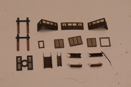
In between jobs, we have also been busy with all kinds of deck equipment parts

P1021583.JPG

P1021584.JPG

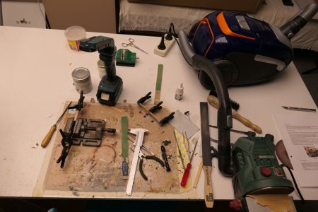
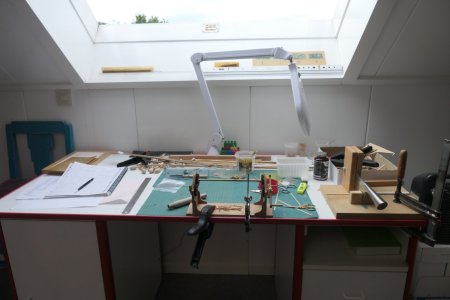
As a bonus this time, a little impression of my shipyard in the attic at the moment

P1021590.JPG

P1021588.JPG

P1021587.JPG

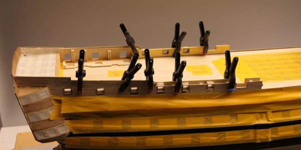
I then started working out the inner bulwarks on the aft deck and the inner and outer bulwarks of the foredeck. I completely prepared these parts ex-situ first, before they could be assembled into the hull painted and already. I did this deliberately because a lot of fiddling and painting goes into this best, which is not so convenient in the hull.

In the pictures below, both the front and back of these parts are listed.

P1021593.JPG

P1021594.JPG

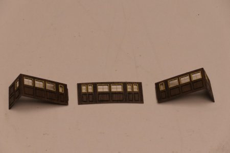
The two left parts concerning bulwarks in the officers' quarters, under the Poop deck that is. In fact, nothing needs to be done here, just some painting

On the inner bulwark of the visible part of the rear deck (the middle set), a number of different parts have to be glued, in combination with a moulding. Using some photos, I drew the layout on the bulwark, after which the moulding could be made. I made this moulding from 1 mm brass wire.

The set on the right concerns the inner and outer bulwarks of the foredeck

P1021597.JPG

Then everything that needed to be yellow was painted twice with yellow (primer) paint for good coverage.
All other black parts painted twice with black paint.

P1021598.JPG

In between, also put the glass in the windows of the officers rooms and glued with a few drops of wood glue.

P1021600.JPG

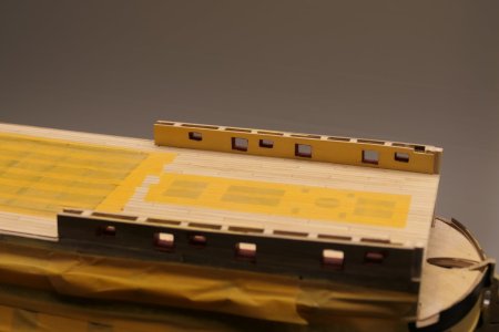
After fitting the outer bulwark on the foredeck, this looks as follows

P1021604.JPG

P1021605.JPG

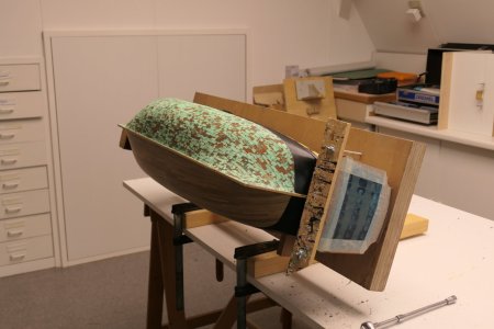
In between, an action photo. All openings in the fuselage well taped, as there was a lot of filing and sanding to be done. In this photo you can also clearly see the progress of ageing the copper plating. As you can see, almost the entire surface is now coloured green.

IMG20231102102726.jpg

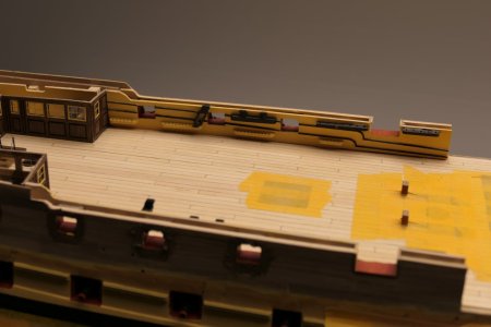
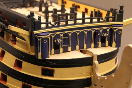
Following this, the aft deck could be decorated.

P1021612.JPG

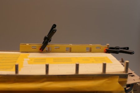
The bulwarks are now all fitted and finished on the outside. The next step is to mount the top covers. These are now also ready to be painted black.

P1021609.JPG

P1021610.JPG
 
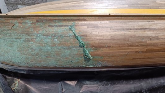
19 - Coppering part 2

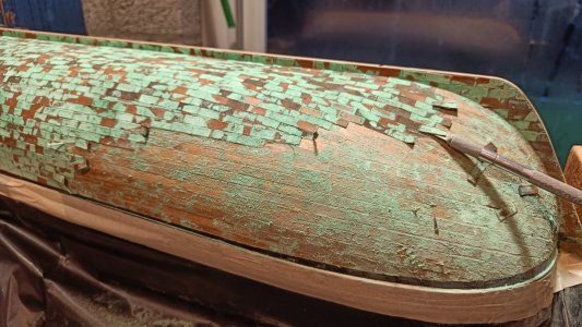
The progressive understanding surrounding my patination project began to reach its peak after six months. The formation of the copper salts on the copper plates had now progressed to the point of almost complete coverage.

P1021616.JPG

P1021617.JPG

This progression process I wanted to start stopping. I had thought of the following:
I pulled out the sample plate I made at the time. Again, the process continued.

P1020982.JPG

Sample 1: this has had no treatment from the start
I brushed the right part with the metal brush on the drill. It is easy to see how much copper salts are released in the process.
On the left part, I used my finger to smear the salts over the plates.

P1021618.JPG

After vacuuming the place, it looks like this. For imaging purposes, I have added a few original pictures. These clearly show that they have also been infected with the salt virus in one way or another.

P1021619.JPG

Sample 2 was the test piece, which I finished with water-based varnish after the first brushing. I have now brushed this again but I don't think this is a success

P1021621.JPG

I also brushed sample 4 at the time and now again.

P1021620.JPG

Personally, I think this is the best result for now

By now, we were 3 weeks on again and it looks like the whole process is about to hit rock bottom.
What happened?

So back to my plan for a moment:
I want to finish the panels with matt varnish.
For specimen 1 right and 4 is then the copper salts were brushed off
For sample 2, I want to more or less mix the smeared copper salt into the first coat of paint. I then expect to get an even greener look, as is the case with many museum ships now. Then finish with a second coat of varnish.
The result of this intention is as follows:

Sample 1:
Right brushed off all the green copper salts, left smeared all the salts with my finger, then water-based varnish over it.
The result: on the left everything starts to peel off and on the right the greening continues.
in other words: NO SUCCESS

P1021739 bew.JPG

Perhaps this could be due to the fact that I used water-based varnish. My next idea was therefore, use a synthetic varnish, which is a bit stronger and may have other properties.

Well:
For the synthetic varnish, I used a glossy boat varnish that I still had on hand. After applying a good layer, which also filled all seams, the whole thing will look very cool. However now, after 3 weeks, a green deposit is still developing under this layer of varnish. On the picture below on the right you can see that the layer of varnish can be easily scraped off with my fingernail.
in other words: NO SUCCESS

P1021741.JPG

My conclusions:
  • I did not handle the patination of the copper plates well at first by dipping the longer ones in the mixture of salt, vinegar and ammonia
  • Patinating the plates one by one in a customary manner is no do.
  • So pre-accelerated patination is not an option.
  • My approach creates a green salt formation that is unstoppable.
  • Covering and insulating with a varnish coating does not help.
in other words, I WAS BACK AT SLOPER HEIGHT, EVERYTHING SHOULD BE REMOVED!

But
  • I was reluctant to remove the plates, especially the tape residue. But we'll see.
  • I will definitely reapply the new plates with double-sided adhesive tape.
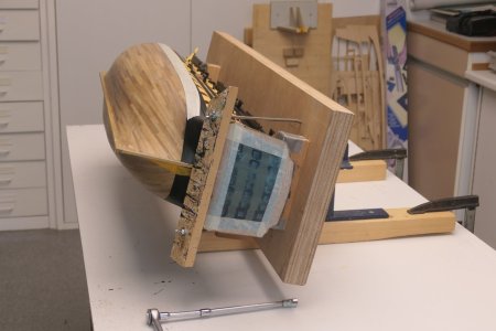
  • An additional problem now is that I can no longer mount the fuselage on the tilt attachment, so I have to come up with something new for that so as not to damage the decks that are now largely furnished.
  • Applying the plates what a nice project at the time, so I try to look forward to that.
in other words: IT IS NOT OTHERS!
 
Hi Wil
Interesting progress

I have a question regarding the way you installed/glued the copper plates.
You indicate that you are using double sided tape.
Do you put the tape on each individual plate and then on the hull
Or do you put a piece of tape on the hull and then install the plates.
I am curious on the approach you are using.,

Thanks
 
Hello Gilbert,
First I put a long piece of tape on the hull.
Then piece by piece the copperplates.
It is very easy and relaxed.
No shit with glue.
When you want more details, start a personal conversation.
 
20 Furnishing and finishing upper decks

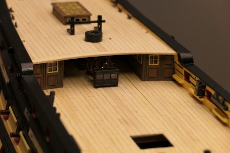
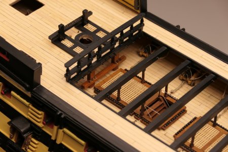
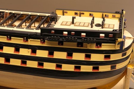
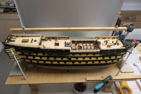
Meanwhile, of course, some constructive things have happened. The poop deck has now been planked and fitted. The topsides of the ship's sides have been sealed and finished and progress has been made on the decking. All in all, several hours to enjoy delightfully.

P1021745.JPG

P1021746.JPG

P1021748.JPG

P1021747.JPG

Been able to get a lot done over the past few weeks, especially a lot of sight work again. A bit of jumping from heel to heel, it seemed, so I started to lose control a bit (I thought). I was afraid I would forget things.
So I grabbed my schedule again. In this planning, for each subproject, for example a certain deck, I have named and listed all parts that I found on the drawings and in the building description. I did this for the entire hull. Then prioritised all subprojects and parts. And then just ticked off until everything was finished.
In my work before as a project manager gave me a lot of peace of mind and after now it still does.
So mainly adding things here and there that had been forgotten. A bit of painting everywhere, etc.
The photos below give a good idea of the current state of work.

P1021760.JPG

P1021766.JPG

P1021768.JPG

P1021776.JPG

P1021780.JPG

P1021816.JPG

For statistics, I am currently sitting on around 800 hours of construction time. When I started, I estimated the total at 4000 hours, spread over 4 years. Roughly 2 years for the hull and 2 years for the masts and rigging. That would mean I would spend an average of 20 hours a week building. That turns out, I now think, to have been a very generous estimate.
The centre section of the ship is now mostly finished. What remains to be done here are the guns on the upper decks, the chain plates and re-coppering the hull on one side. This will be followed by the bow, galleries and stern. The hatches, the dummy guns and the railing around the coaming I have deemed too fragile, those will come much later.
It was full of enjoyment again with the final details, such as the main staircase, the buckets, the rests with the deadeyes and the two stairs to the poop deck. I think details like these are kind of the icing on the cake anyway.
Earlier, a colleague gave me a list of things not to forget especially while building the hull. This was mainly about fitting holes and eyelets, which will be indispensable later for the ropework. Many of these things would already be inaccessible at this point. It's a good thing there are a few Victory veterans looking in on our build reports, it prevents a lot of misery later on. I took his instructions to heart, although it was still quite a puzzle here and there.
One more technical aspect regarding the paintwork. I first treat all metal parts with a multiprimer before applying colour. In this case, usually black, turpentine-based. The paint for the woodwork is water-based. When applying various parts, disturbing effects arise because of the gloss of the glue versus the matt paint. I solve this by treating everything again with matt varnish after assembly, so that everything has the same matt appearance. An additional effect is that the varnish also strengthens the final paint layer. In between, I drilled all the holes and eyelets again, so that later the ropes can be fed through with ease.

Finally, I want to leave you with the final details of this week.

P1021798.JPG

P1021799.JPG

P1021811.JPG

P1021780.JPG

P1021814.JPG

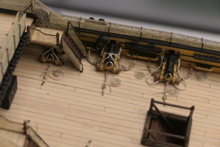
Meanwhile, the carronades have also been assembled in place. To be honest, assembling the carronades was one of the first things I did when I started building the kit. After all, I had to get some sense that I was working on a warship. The ropework is from the last few weeks, though.

P1022917.JPG

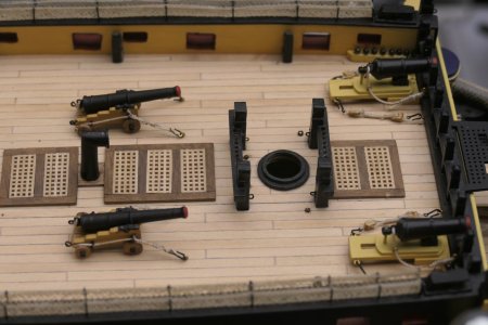
Currently, the 6 guns on the aft deck are also installed. The two guns under the stairs are missing the catch-up tackles, I couldn't reach them anymore. I also made two variations of the troot brails. Seemed like fun, add a ball of string and Wil is ready.

P1022964.JPG

The two guns on the foredeck are the last ones. Four more tackles need to be attached to these and then the gun project will be complete. The dummies for the 1e and 2e gun decks will be installed when the hatches are fitted.

P1022965.JPG

All in all, it will be quite a ship by the time the hull is almost finished.

P1022966.JPG

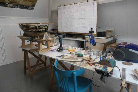
In between, a quick look at the shipyard. Because I am working on so many things at once, I currently have 4 workstations. I drag the blue chair from place to place. It's great to have an attic room like this, where you can leave everything and only have to switch off the lamp.

P1022943.JPG

P1022942.JPG
 
20 Furnishing and finishing upper decks

Meanwhile, of course, some constructive things have happened. The poop deck has now been planked and fitted. The topsides of the ship's sides have been sealed and finished and progress has been made on the decking. All in all, several hours to enjoy delightfully.

View attachment 515879

View attachment 515880

View attachment 515881

View attachment 515882

Been able to get a lot done over the past few weeks, especially a lot of sight work again. A bit of jumping from heel to heel, it seemed, so I started to lose control a bit (I thought). I was afraid I would forget things.
So I grabbed my schedule again. In this planning, for each subproject, for example a certain deck, I have named and listed all parts that I found on the drawings and in the building description. I did this for the entire hull. Then prioritised all subprojects and parts. And then just ticked off until everything was finished.
In my work before as a project manager gave me a lot of peace of mind and after now it still does.
So mainly adding things here and there that had been forgotten. A bit of painting everywhere, etc.
The photos below give a good idea of the current state of work.

View attachment 515883

View attachment 515884

View attachment 515885

View attachment 515886

View attachment 515887

View attachment 515888

For statistics, I am currently sitting on around 800 hours of construction time. When I started, I estimated the total at 4000 hours, spread over 4 years. Roughly 2 years for the hull and 2 years for the masts and rigging. That would mean I would spend an average of 20 hours a week building. That turns out, I now think, to have been a very generous estimate.
The centre section of the ship is now mostly finished. What remains to be done here are the guns on the upper decks, the chain plates and re-coppering the hull on one side. This will be followed by the bow, galleries and stern. The hatches, the dummy guns and the railing around the coaming I have deemed too fragile, those will come much later.
It was full of enjoyment again with the final details, such as the main staircase, the buckets, the rests with the deadeyes and the two stairs to the poop deck. I think details like these are kind of the icing on the cake anyway.
Earlier, a colleague gave me a list of things not to forget especially while building the hull. This was mainly about fitting holes and eyelets, which will be indispensable later for the ropework. Many of these things would already be inaccessible at this point. It's a good thing there are a few Victory veterans looking in on our build reports, it prevents a lot of misery later on. I took his instructions to heart, although it was still quite a puzzle here and there.
One more technical aspect regarding the paintwork. I first treat all metal parts with a multiprimer before applying colour. In this case, usually black, turpentine-based. The paint for the woodwork is water-based. When applying various parts, disturbing effects arise because of the gloss of the glue versus the matt paint. I solve this by treating everything again with matt varnish after assembly, so that everything has the same matt appearance. An additional effect is that the varnish also strengthens the final paint layer. In between, I drilled all the holes and eyelets again, so that later the ropes can be fed through with ease.

Finally, I want to leave you with the final details of this week.

View attachment 515889

View attachment 515890

View attachment 515891

View attachment 515892

View attachment 515893

Meanwhile, the carronades have also been assembled in place. To be honest, assembling the carronades was one of the first things I did when I started building the kit. After all, I had to get some sense that I was working on a warship. The ropework is from the last few weeks, though.

View attachment 515894

Currently, the 6 guns on the aft deck are also installed. The two guns under the stairs are missing the catch-up tackles, I couldn't reach them anymore. I also made two variations of the troot brails. Seemed like fun, add a ball of string and Wil is ready.

View attachment 515895

The two guns on the foredeck are the last ones. Four more tackles need to be attached to these and then the gun project will be complete. The dummies for the 1e and 2e gun decks will be installed when the hatches are fitted.

View attachment 515896

All in all, it will be quite a ship by the time the hull is almost finished.

View attachment 515897

In between, a quick look at the shipyard. Because I am working on so many things at once, I currently have 4 workstations. I drag the blue chair from place to place. It's great to have an attic room like this, where you can leave everything and only have to switch off the lamp.

View attachment 515898

View attachment 515899
Very good progress WIl
And a very nice shipyard.
Cheers
 
20 Furnishing and finishing upper decks

Meanwhile, of course, some constructive things have happened. The poop deck has now been planked and fitted. The topsides of the ship's sides have been sealed and finished and progress has been made on the decking. All in all, several hours to enjoy delightfully.

View attachment 515879

View attachment 515880

View attachment 515881

View attachment 515882

Been able to get a lot done over the past few weeks, especially a lot of sight work again. A bit of jumping from heel to heel, it seemed, so I started to lose control a bit (I thought). I was afraid I would forget things.
So I grabbed my schedule again. In this planning, for each subproject, for example a certain deck, I have named and listed all parts that I found on the drawings and in the building description. I did this for the entire hull. Then prioritised all subprojects and parts. And then just ticked off until everything was finished.
In my work before as a project manager gave me a lot of peace of mind and after now it still does.
So mainly adding things here and there that had been forgotten. A bit of painting everywhere, etc.
The photos below give a good idea of the current state of work.

View attachment 515883

View attachment 515884

View attachment 515885

View attachment 515886

View attachment 515887

View attachment 515888

For statistics, I am currently sitting on around 800 hours of construction time. When I started, I estimated the total at 4000 hours, spread over 4 years. Roughly 2 years for the hull and 2 years for the masts and rigging. That would mean I would spend an average of 20 hours a week building. That turns out, I now think, to have been a very generous estimate.
The centre section of the ship is now mostly finished. What remains to be done here are the guns on the upper decks, the chain plates and re-coppering the hull on one side. This will be followed by the bow, galleries and stern. The hatches, the dummy guns and the railing around the coaming I have deemed too fragile, those will come much later.
It was full of enjoyment again with the final details, such as the main staircase, the buckets, the rests with the deadeyes and the two stairs to the poop deck. I think details like these are kind of the icing on the cake anyway.
Earlier, a colleague gave me a list of things not to forget especially while building the hull. This was mainly about fitting holes and eyelets, which will be indispensable later for the ropework. Many of these things would already be inaccessible at this point. It's a good thing there are a few Victory veterans looking in on our build reports, it prevents a lot of misery later on. I took his instructions to heart, although it was still quite a puzzle here and there.
One more technical aspect regarding the paintwork. I first treat all metal parts with a multiprimer before applying colour. In this case, usually black, turpentine-based. The paint for the woodwork is water-based. When applying various parts, disturbing effects arise because of the gloss of the glue versus the matt paint. I solve this by treating everything again with matt varnish after assembly, so that everything has the same matt appearance. An additional effect is that the varnish also strengthens the final paint layer. In between, I drilled all the holes and eyelets again, so that later the ropes can be fed through with ease.

Finally, I want to leave you with the final details of this week.

View attachment 515889

View attachment 515890

View attachment 515891

View attachment 515892

View attachment 515893

Meanwhile, the carronades have also been assembled in place. To be honest, assembling the carronades was one of the first things I did when I started building the kit. After all, I had to get some sense that I was working on a warship. The ropework is from the last few weeks, though.

View attachment 515894

Currently, the 6 guns on the aft deck are also installed. The two guns under the stairs are missing the catch-up tackles, I couldn't reach them anymore. I also made two variations of the troot brails. Seemed like fun, add a ball of string and Wil is ready.

View attachment 515895

The two guns on the foredeck are the last ones. Four more tackles need to be attached to these and then the gun project will be complete. The dummies for the 1e and 2e gun decks will be installed when the hatches are fitted.

View attachment 515896

All in all, it will be quite a ship by the time the hull is almost finished.

View attachment 515897

In between, a quick look at the shipyard. Because I am working on so many things at once, I currently have 4 workstations. I drag the blue chair from place to place. It's great to have an attic room like this, where you can leave everything and only have to switch off the lamp.

View attachment 515898

View attachment 515899
Good evening. I agree with Gilbert. This is a fabulous build of the HmS Victory. Great progress. Cheers Grant
 
Back
Top