-

Win a Free Custom Engraved Brass Coin!!!
As a way to introduce our brass coins to the community, we will raffle off a free coin during the month of August. Follow link ABOVE for instructions for entering.
-

PRE-ORDER SHIPS IN SCALE TODAY!
The beloved Ships in Scale Magazine is back and charting a new course for 2026!
Discover new skills, new techniques, and new inspirations in every issue.
NOTE THAT OUR FIRST ISSUE WILL BE JAN/FEB 2026
You are using an out of date browser. It may not display this or other websites correctly.
You should upgrade or use an alternative browser.
You should upgrade or use an alternative browser.
Le Saint Philippe 1693 after Jean-Claude Lemineur (Ancre) in scale 1:48
- Thread starter dockattner
- Start date
- Watchers 80
-
- Tags
- 1:48 ancre saint philippe
A thoughts to add to the discussion about the angle of the frames relative to the keel and/or waterline:
The advantage of all frames perpendicular to the waterline: all interior walls connected to the frames will also be straight.
In my opinion you are on the right track, Paul. However, given the position of the frames relative to the keel of 1.5 dgr and perpendicular to the waterline in my Balder, my opinion may be biased.
But 'stuurlast/steering load' is a factor that has a positive effect on the sailing characteristics of a ship.
Regards, Peter
The advantage of all frames perpendicular to the waterline: all interior walls connected to the frames will also be straight.
In my opinion you are on the right track, Paul.
But 'stuurlast/steering load' is a factor that has a positive effect on the sailing characteristics of a ship.
Regards, Peter
- Joined
- Dec 10, 2024
- Messages
- 1
- Points
- 13
je travaille actuellement sur les plans de la Néréide, de JC Lemineur aussi. https://5500.forumactif.org/t4659-la-nereide-au-48e-par-eric-l-emaillet
Je rencontre les mêmes problèmes, dessins mal faits, ne respectant pas les règles habituelles du dessin de monographie, aucun commentaire des planches, manque de correspondance entre les différentes planches, etc.
cet auteur n'est pas une bonne publicité pour Ancre, qui a par ailleurs d'excellents auteurs. Mes difficultés ne viennent pas du fait que je sois débutant https://sites.google.com/view/modelismenavaldarsenal/accueil
bon courage pour le St Philippe.
I'm currently working on the plans for the Néréide, also by JC Lemineur. https://5500.forumactif.org/t4659-la-nereide-au-48e-par-eric-l-emailletI'm having the same problems: poorly done drawings that don't follow the usual rules for drawing in a monograph, no commentary on the plates, a lack of correspondence between the different plates, etc.This author isn't a good advertisement for Ancre, which also has excellent authors. My difficulties aren't due to the fact that I'm a beginner. https://sites.google.com/view/modelismenavaldarsenal/accueilGood luck with the St. Philippe.
- Joined
- Aug 8, 2019
- Messages
- 5,568
- Points
- 738

I completely agree with Peter here. If you built a 17 century Dutchman the keel was stacked on blocks (Yk/Witsen). Such that the keel tilted back a bit. If the frames were placed using a plumb line they were not perpendicular to the keel but to the waterline. With a Dutchman it could be even worse because there the keel hung through in the middle and that meant that the frames at the front were even at a different angle to the keel.This is all about the ‘trim’ of a ship.
Here’s a interesting article: MaritimePage
The main conclusion:
The term “trim” refers to the fore-and-aft balance of a ship It is the difference between the draft forward and aft. When a vessel is properly trimmed, her stern sits lower in the water than her bow, which gives her more speed and maneuverability. The word “trim” can also be used to refer to the act of adjusting a ship’s ballast to achieve this ideal balance.
Maarten @Maarten also wrote about thatin post #15:
the draft on the rear is more than at the bow
As you already made a ramp of 1.2 dgr under you keel, the frames are not tilted ……Rotate that part of the drawings 1.2 dgr counterclockwise and they are standing correct ……
in opposite of the waterline. It’s common to build the frame perpendiculair to the waterline and the constructor determines how much trim they want to give the ship/keel.
Regards, Peter
Thanks for continuing to think this through, Peter. I appreciate your contribution.A thoughts to add to the discussion about the angle of the frames relative to the keel and/or waterline:
The advantage of all frames perpendicular to the waterline: all interior walls connected to the frames will also be straight.
In my opinion you are on the right track, Paul.However, given the position of the frames relative to the keel of 1.5 dgr and perpendicular to the waterline in my Balder, my opinion may be biased.
But 'stuurlast/steering load' is a factor that has a positive effect on the sailing characteristics of a ship.
Regards, Peter
Greetings, Eric. I am familiar with your magnificent work. Indeed, you are not a beginner!je travaille actuellement sur les plans de la Néréide, de JC Lemineur aussi. https://5500.forumactif.org/t4659-la-nereide-au-48e-par-eric-l-emaillet
Je rencontre les mêmes problèmes, dessins mal faits, ne respectant pas les règles habituelles du dessin de monographie, aucun commentaire des planches, manque de correspondance entre les différentes planches, etc.
cet auteur n'est pas une bonne publicité pour Ancre, qui a par ailleurs d'excellents auteurs. Mes difficultés ne viennent pas du fait que je sois débutant https://sites.google.com/view/modelismenavaldarsenal/accueil
bon courage pour le St Philippe.
I'm currently working on the plans for the Néréide, also by JC Lemineur. https://5500.forumactif.org/t4659-la-nereide-au-48e-par-eric-l-emailletI'm having the same problems: poorly done drawings that don't follow the usual rules for drawing in a monograph, no commentary on the plates, a lack of correspondence between the different plates, etc.This author isn't a good advertisement for Ancre, which also has excellent authors. My difficulties aren't due to the fact that I'm a beginner. https://sites.google.com/view/modelismenavaldarsenal/accueilGood luck with the St. Philippe.
Understood. Setting the frames is not the difficulty (Maarten and Nigel provided a very elegant solution). It is the uncertain perspective of the other 40 drawings that is creating difficulties.I completely agree with Peter here. If you built a 17 century Dutchman the keel was stacked on blocks (Yk/Witsen). Such that the keel tilted back a bit. If the frames were placed using a plumb line they were not perpendicular to the keel but to the waterline. With a Dutchman it could be even worse because there the keel hung through in the middle and that meant that the frames at the front were even at a different angle to the keel.
I want Paul’s job…he is as always somewhere around the world on holiday……The only pictures are people with fish...
View attachment 534776 View attachment 534778 View attachment 534777 View attachment 534779
Our 'second official' 40th Anniversary trip comes in a month (Prague, Nuremberg, Danube River through Germany and Austria, finishing in Budapest).
 . As for the “angle of the dangle “ I will leave that conversation to the experts.
Cool pics Paul.
Cheers Grant
PS I don’t really want Paul’s job as there would be a lot of people with screw teeth
 .
.- Joined
- Sep 10, 2024
- Messages
- 1,022
- Points
- 393

Something has been bugging me as I've followed along, Paul. Early on, you solved the issue of how to build the leaning frames by raising the forward end of the keel 1.2 deg., allowing you to place the frames at 90 deg. to your building board. Exactly what I would have done. However, and this just may be a trick of the eye or camera or perspective, in each photo you have posted that shows a broadside view, it appears that the frames are indeed leaning forward, even though the keel still looks elevated at the forward end. While things were still in the fixture, I thought it was the sloped top frame that gave the illusion that the frames were tilted, so I didn't say anything at the time.
Subsequent pictures have me wondering, though - you didn't by any chance elevate the keel AND tip the frames forward, forgetting that the keel was elevated?
Subsequent pictures have me wondering, though - you didn't by any chance elevate the keel AND tip the frames forward, forgetting that the keel was elevated?
- Joined
- Aug 8, 2019
- Messages
- 5,568
- Points
- 738

You can start a living in the UK in that case, nobody will notice.PS I don’t really want Paul’s job as there would be a lot of people with screw teeth.
Nope. The forward keel was elevated and I used a perfect perpendicular to the base to install the frames. It may just be something in the way I took the photos - or maybe the forward keel wasn't pushed all the way down to the board while taking pictures (it has a robust friction fit between the guides rails). But I do appreciate you sharing your concern! I'm certainly capable of messing this up!Something has been bugging me as I've followed along, Paul. Early on, you solved the issue of how to build the leaning frames by raising the forward end of the keel 1.2 deg., allowing you to place the frames at 90 deg. to your building board. Exactly what I would have done. However, and this just may be a trick of the eye or camera or perspective, in each photo you have posted that shows a broadside view, it appears that the frames are indeed leaning forward, even though the keel still looks elevated at the forward end. While things were still in the fixture, I thought it was the sloped top frame that gave the illusion that the frames were tilted, so I didn't say anything at the time.
Subsequent pictures have me wondering, though - you didn't by any chance elevate the keel AND tip the frames forward, forgetting that the keel was elevated?
Hi Paul, if you need an extra pair of eyes I do have these drawings and the monograph. Just let me know.Understood. Setting the frames is not the difficulty (Maarten and Nigel provided a very elegant solution). It is the uncertain perspective of the other 40 drawings that is creating difficulties.
Unfortunately, all the drawings are just sketches... the only thing that can give a complete picture is 3D, but there are few such models and working on them takes a huge amount of time and effort, and those who did this are naturally right to ask for monetary compensation for this. Otherwise - suffer with "drawings"
Hello Friends,
I had hoped this would be a major update, but alas...
I continue to struggle with the challenges inherent to scratch building. Namely, the more complex the part the more difficult it is for me to visualize what the drawings represent. Plus, determining a proper build sequence is elusive. It seems that if I could install certain parts... that would provide some helpful constraint to the shaping of subsequent parts. But if I install those certain parts, it precludes correcting them (or further shaping them / sanding them). Basically, my lack of experience has profoundly slowed progress.
In my last progress report I celebrated the installation of all frames that originate at the centerline. Aft of that there are to be two more frames. One of these is the top timber that goes on top of the fashion pieces. This forms the corner between the side of the ship and the stern of the ship (that is - it needs to be perfect). There is an additional filler timber between that top timber and the last frame previously installed.
Across the lower portion of the stern there are eight stern counter timbers - and then above that are a series of upper counter timbers. These items relate one to the other.
Here are the lower and upper counter timbers during fabrication:
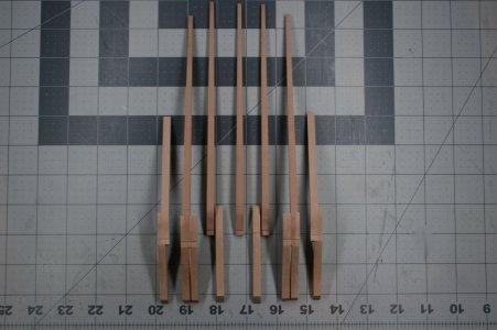
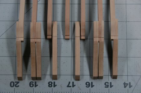
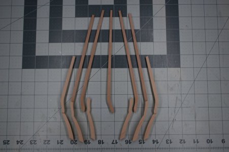
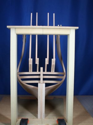
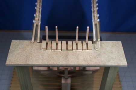
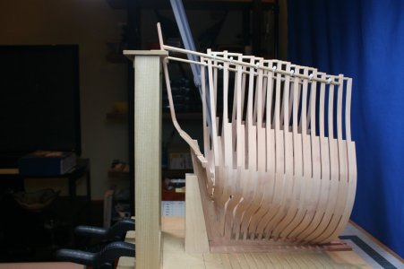
In order to control the position of the counter timbers I made a jig:
I mentioned the top timber that sits above the fashion pieces (forming the corner of the ship in the back). That piece is a 3D marvel that shares the profile of the counter timbers I just showed - but it also follows the curves of the ship hull (effectively making this piece S-shaped when viewed from the stern).
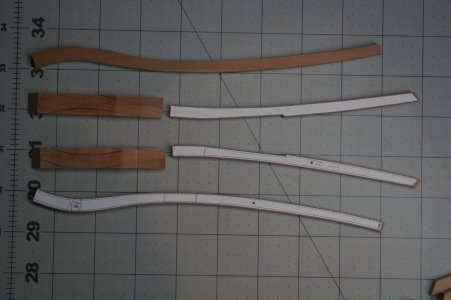
In the center of the image shown below you can see this vexing part. My first attempt was long ago abandoned. This was the second attempt. It has also been binned after an investment of nearly a full day. I made the mistake of trusting the drawing of the filler frame (labeled #18 in the picture below) when creating the curved portion of the fashion piece top-timber.
Anyway, I have given up for the day and will make another attempt over the weekend.
I'm sure you are familiar with the "I don't think I can build this thing" feeling...
I had hoped this would be a major update, but alas...
I continue to struggle with the challenges inherent to scratch building. Namely, the more complex the part the more difficult it is for me to visualize what the drawings represent. Plus, determining a proper build sequence is elusive. It seems that if I could install certain parts... that would provide some helpful constraint to the shaping of subsequent parts. But if I install those certain parts, it precludes correcting them (or further shaping them / sanding them). Basically, my lack of experience has profoundly slowed progress.
In my last progress report I celebrated the installation of all frames that originate at the centerline. Aft of that there are to be two more frames. One of these is the top timber that goes on top of the fashion pieces. This forms the corner between the side of the ship and the stern of the ship (that is - it needs to be perfect). There is an additional filler timber between that top timber and the last frame previously installed.
Across the lower portion of the stern there are eight stern counter timbers - and then above that are a series of upper counter timbers. These items relate one to the other.
Here are the lower and upper counter timbers during fabrication:


In order to control the position of the counter timbers I made a jig:


I mentioned the top timber that sits above the fashion pieces (forming the corner of the ship in the back). That piece is a 3D marvel that shares the profile of the counter timbers I just showed - but it also follows the curves of the ship hull (effectively making this piece S-shaped when viewed from the stern).
In the center of the image shown below you can see this vexing part. My first attempt was long ago abandoned. This was the second attempt. It has also been binned after an investment of nearly a full day. I made the mistake of trusting the drawing of the filler frame (labeled #18 in the picture below) when creating the curved portion of the fashion piece top-timber.
Anyway, I have given up for the day and will make another attempt over the weekend.

I'm sure you are familiar with the "I don't think I can build this thing" feeling...
Paul,Hello Friends,
I had hoped this would be a major update, but alas...
I continue to struggle with the challenges inherent to scratch building. Namely, the more complex the part the more difficult it is for me to visualize what the drawings represent. Plus, determining a proper build sequence is elusive. It seems that if I could install certain parts... that would provide some helpful constraint to the shaping of subsequent parts. But if I install those certain parts, it precludes correcting them (or further shaping them / sanding them). Basically, my lack of experience has profoundly slowed progress.
In my last progress report I celebrated the installation of all frames that originate at the centerline. Aft of that there are to be two more frames. One of these is the top timber that goes on top of the fashion pieces. This forms the corner between the side of the ship and the stern of the ship (that is - it needs to be perfect). There is an additional filler timber between that top timber and the last frame previously installed.
Across the lower portion of the stern there are eight stern counter timbers - and then above that are a series of upper counter timbers. These items relate one to the other.
Here are the lower and upper counter timbers during fabrication:
View attachment 536861
View attachment 536862
View attachment 536863
In order to control the position of the counter timbers I made a jig:
View attachment 536867
View attachment 536868
View attachment 536869
I mentioned the top timber that sits above the fashion pieces (forming the corner of the ship in the back). That piece is a 3D marvel that shares the profile of the counter timbers I just showed - but it also follows the curves of the ship hull (effectively making this piece S-shaped when viewed from the stern).
In the center of the image shown below you can see this vexing part. My first attempt was long ago abandoned. This was the second attempt. It has also been binned after an investment of nearly a full day. I made the mistake of trusting the drawing of the filler frame (labeled #18 in the picture below) when creating the curved portion of the fashion piece top-timber.
Anyway, I have given up for the day and will make another attempt over the weekend.
View attachment 536864
I'm sure you are familiar with the "I don't think I can build this thing" feeling...
You've made it farther than most, and I, for one, have no doubts you're going to nail it in the end. I think your current approach--to give it some time for your brain to percolate--is going to prove efficacious. The wondrous thing about the human brain is that it works best at solving problems when you're not actively trying to solve that problem.
Paul,
Even though you see yourself with nothing but problems with this build, I feel you are doing an astounding job. It may take you a little time to figure it out, but that is always part of the challenge.
Even though you see yourself with nothing but problems with this build, I feel you are doing an astounding job. It may take you a little time to figure it out, but that is always part of the challenge.
Thank you, my friend. Great wisdom here. Someone else (Marc) posted something similar (his advice was just keep looking at the drawings until it becomes clear). I have certainly been putting these ideas into play...but I also seem to learn when I try to make something and encounter failure. The waste of wood and time is regrettable - but seeing the part in situ helps me problem solve. Let's see what comes of it all... Your encouragement gives me some fuel.Paul,
You've made it farther than most, and I, for one, have no doubts you're going to nail it in the end. I think your current approach--to give it some time for your brain to percolate--is going to prove efficacious. The wondrous thing about the human brain is that it works best at solving problems when you're not actively trying to solve that problem.
Thank you, Jeff. If this was easy, I suspect many of us would opt for a different hobby.Paul,
Even though you see yourself with nothing but problems with this build, I feel you are doing an astounding job. It may take you a little time to figure it out, but that is always part of the challenge.
Remember, Rome was not built in a day !Thank you, Jeff. If this was easy, I suspect many of us would opt for a different hobby.
I bet it will suddenly come to you and you'll think "Why couldn't I see this before!"
- Joined
- Jun 17, 2021
- Messages
- 3,200
- Points
- 588

Neither the time nor the material are wasted.
And (as I have heard said) " If it was easy everybody would do it."
The nice thing about working with gold as opposed to a precious stash of boxwood or Swiss pear, is that you can just melt down the gold and start over.
I, for one, am enthralled with your efforts, process and progress. I love what I'm seeing. It reminds me of the things my dad was able to come up with seemingly out of thin air. I believe he would be impressed and proud of your work. He (Robert P. Gutterman) has patents online and an award from the Navy during WWII.
You have a very analytical mind. As did my dad. Me, not as much.


