-

Win a Free Custom Engraved Brass Coin!!!
As a way to introduce our brass coins to the community, we will raffle off a free coin during the month of August. Follow link ABOVE for instructions for entering.
-

PRE-ORDER SHIPS IN SCALE TODAY!
The beloved Ships in Scale Magazine is back and charting a new course for 2026!
Discover new skills, new techniques, and new inspirations in every issue.
NOTE THAT OUR FIRST ISSUE WILL BE JAN/FEB 2026
You are using an out of date browser. It may not display this or other websites correctly.
You should upgrade or use an alternative browser.
You should upgrade or use an alternative browser.
HMS Agamemnon by Caldercraft
- Thread starter HMSFly
- Start date
- Watchers 32
-
- Tags
- agamemnon caldercraft
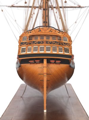
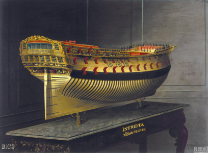
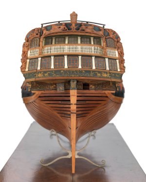
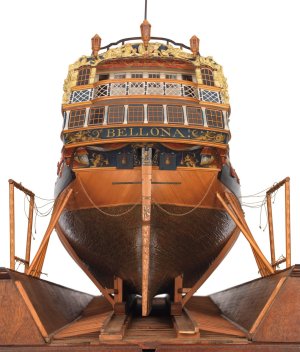
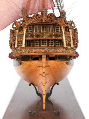
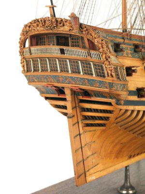
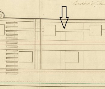
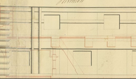
Dear Mark! I took another look at your blog. You still haven't used the museum's ship plans, have you? Download the plans from these links; they have high-resolution images. These drawings are very important. Comparing archival drawings and photographs of the Agamemnon model, I suddenly discovered a huge error by Chris Watton that made my hair stand on end! I recommend immediately halting work on the upper deck and superstructure. I also strongly urge you to take high-quality photographs of the upper deck and superstructure plans from the instructions, as well as a longitudinal section. Throw them here or send them to me in a letter, and I will make notes on these pictures. Please take photos of the instructions large enough for me to properly mark and draw on them. I'll show you something that will make you fall off your chair!


 commons.wikimedia.org

 commons.wikimedia.org

 commons.wikimedia.org

 commons.wikimedia.org
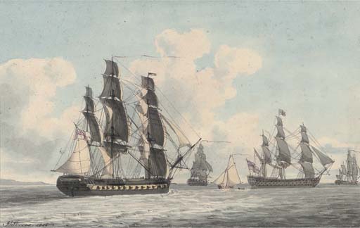
 commons.wikimedia.org

 commons.wikimedia.org

 commons.wikimedia.org

 commons.wikimedia.org

 commons.wikimedia.org

 commons.wikimedia.org

File:'Ardent' (1764); 'Nassau' (1785) RMG J3362.png - Wikimedia Commons

File:'Ardent' (1764); 'Nassau' (1785) RMG J3360.png - Wikimedia Commons

File:'Ardent' (1764); 'Nassau' (1785) RMG J3359.png - Wikimedia Commons

File:'Ardent' (1764); 'Nassau' (1785) RMG J3361.png - Wikimedia Commons

Category:HMS Indefatigable (ship, 1784) - Wikimedia Commons

Category:HMS Nassau (ship, 1785) - Wikimedia Commons

Category:HMS Nassau (ship, 1785) - Wikimedia Commons

Category:HMS Nassau (ship, 1785) - Wikimedia Commons

Category:HMS Nassau (ship, 1785) - Wikimedia Commons

Category:HMS Nassau (ship, 1785) - Wikimedia Commons
Last edited:
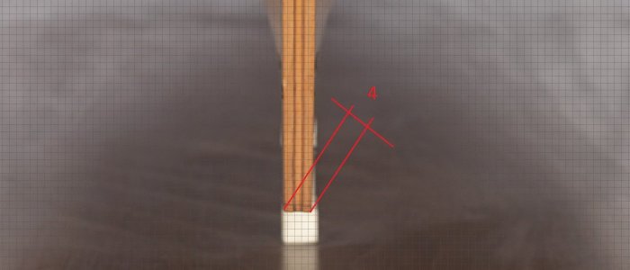
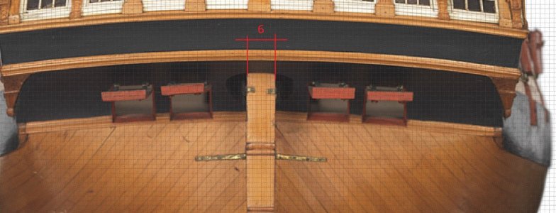
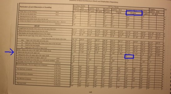
I was curious about the amount of taper for a British 64 and wound up going back to Steel's Elements and Practice of Naval Architecture and the Shipbuilder's Repository as the contracts I have for 64's do not give any the dimension for the fore end of the knee of the head nor do the Establishments. The following may be interesting for various size ships of the second half of the 18th century and into the 19th century. The marked block is for a 64 and shows 5". What surprised me is the amount of taper on a first rate, going from 1' 7 1/2" at the stem down to 6" at the fore end.
Allan
Allan

Ok Iutar wil send you plans by mail...Dear Mark! I took another look at your blog. You still haven't used the museum's ship plans, have you? Download the plans from these links; they have high-resolution images. These drawings are very important. Comparing archival drawings and photographs of the Agamemnon model, I suddenly discovered a huge error by Chris Watton that made my hair stand on end! I recommend immediately halting work on the upper deck and superstructure. I also strongly urge you to take high-quality photographs of the upper deck and superstructure plans from the instructions, as well as a longitudinal section. Throw them here or send them to me in a letter, and I will make notes on these pictures. Please take photos of the instructions large enough for me to properly mark and draw on them. I'll show you something that will make you fall off your chair!

File:'Ardent' (1764); 'Nassau' (1785) RMG J3362.png - Wikimedia Commons
commons.wikimedia.org

File:'Ardent' (1764); 'Nassau' (1785) RMG J3360.png - Wikimedia Commons
commons.wikimedia.org

File:'Ardent' (1764); 'Nassau' (1785) RMG J3359.png - Wikimedia Commons
commons.wikimedia.org

File:'Ardent' (1764); 'Nassau' (1785) RMG J3361.png - Wikimedia Commons
commons.wikimedia.org

Category:HMS Indefatigable (ship, 1784) - Wikimedia Commons
commons.wikimedia.org

Category:HMS Nassau (ship, 1785) - Wikimedia Commons
commons.wikimedia.org

Category:HMS Nassau (ship, 1785) - Wikimedia Commons
commons.wikimedia.org

Category:HMS Nassau (ship, 1785) - Wikimedia Commons
commons.wikimedia.org

Category:HMS Nassau (ship, 1785) - Wikimedia Commons
commons.wikimedia.org

Category:HMS Nassau (ship, 1785) - Wikimedia Commons
commons.wikimedia.org
Wil take time because scale of drawings is A0....en have to take a lot of foto's!
Marc
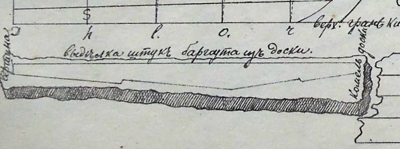
Why "Top and Butt"? Sir Thomas Slade introduced "Hook and Butt" for the third rank. In addition, Slade is the author of the Ardent series. Mr. Dean made a mistake in his book about Nelson's ships, providing inaccurate diagrams. In those days, even the fifth rate was called "Hook and Butt."
Dear Mark, take the ready-made plans shown in message 194. They include an adapted version from the best specialist, Brian Lavery, and a genuine museum drawing by Montague. Simply transfer these plans to the body of your model and confidently create the parts on-site. You don't even have to think, just transfer the museum drawings to the model.
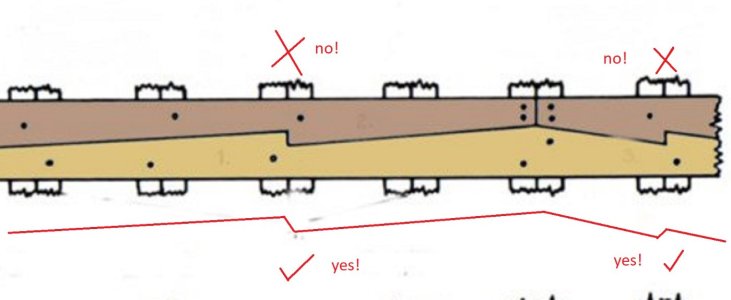
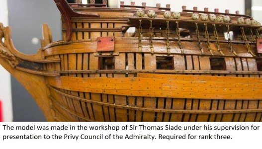
In the photo below, this is what a real hook and butt looks like. Notice the hooks have obtuse angles. Modern draftsmen often draw sharp angles, but in real life, such wooden parts break.


Mails sendWhy "Top and Butt"? Sir Thomas Slade introduced "Hook and Butt" for the third rank. In addition, Slade is the author of the Ardent series. Mr. Dean made a mistake in his book about Nelson's ships, providing inaccurate diagrams. In those days, even the fifth rate was called "Hook and Butt."
Dear Mark, take the ready-made plans shown in message 194. They include an adapted version from the best specialist, Brian Lavery, and a genuine museum drawing by Montague. Simply transfer these plans to the body of your model and confidently create the parts on-site. You don't even have to think, just transfer the museum drawings to the model.
In the photo below, this is what a real hook and butt looks like. Notice the hooks have obtuse angles. Modern draftsmen often draw sharp angles, but in real life, such wooden parts break.
View attachment 547212 View attachment 547213
View attachment 547221
View attachment 547222
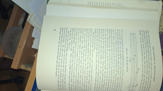
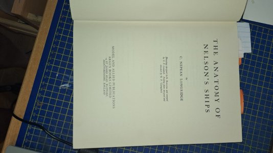
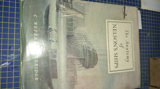
I understand. It's a great book for modelers on how to make a model, but it doesn't provide historically accurate information.The source I used:
Dear Mark, Chapter three of this book clearly demonstrates that Mr. Longridge is completely unaware of the different ways in which "anchor and stock" boards can be installed. Unfortunately, he only knows "top and butt," which fits his description of the Victory ship, which does not have real hull plating.
I have more faith in the actual drawing from those years, the actual model from the great Slade, other models and the real historian Lavery, who directly points to sources from archival materials.
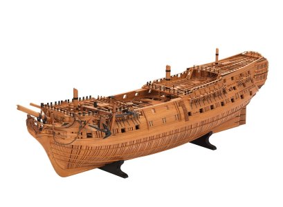
Another model from the Greenwich collection, showing the hook and butt method, third rank, HMS Egmont.
Mark, I looked at the photos. I didn't even expect it to be this bad. There are far more errors than I imagined (you probably spotted some thanks to Mr. Longridge's book).Mails send
But it's going to be a glorious battle!
Unfortunately, I can't tell you all about it right now. I'll need some time to give an overview.
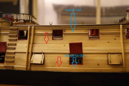
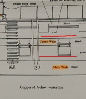
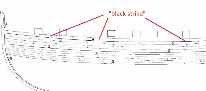
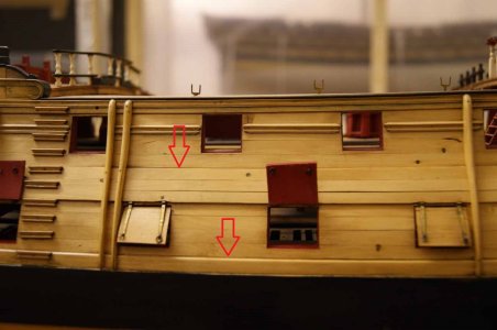
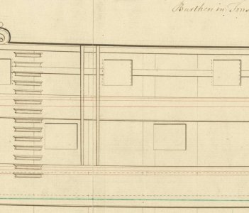
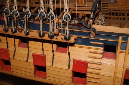
Dear Mark! Since you're currently busy working on the wales, I'd like to point out an error I noticed in your photos. The so-called "black strike" is missing above the main wale. It's clearly visible in the diagrams in post 194.
You should also check the width of the upper wale, as Chris Watton typically adjusts its width to the size of the wooden planks in his designs. On Chris's model the upper wale is clearly smaller in width.
The upper wale should consist of three stripes.
The "black strike" stripe was usually not shown on general drawings, so it's not present on the archived drawings. However, it's clearly visible on the models.


Last edited:
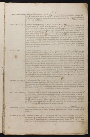
I THINK the black strake would be the same width as the other planking. It is acutally thicker than the planking above and thinner than the wales, but most folks don't go that far. The black strake was the first strake of thick stuff upon the wales. The below gives the various thicknesses and breadths of planking in the contract for Nassau (64) 1782 so should be close if not exactly the same.an I use a 1 x 1 mm strip for the black strike?
Allan
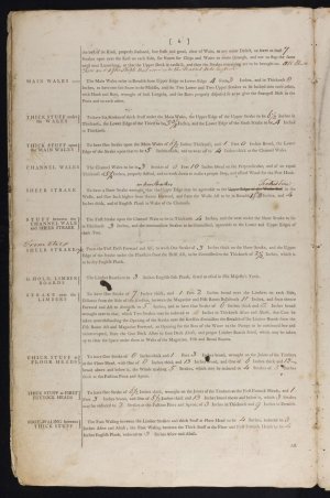
Mark, one more confirmation. 

Mark, the documents Allan found completely match the figures Brian Lavery showed for third-rank ships. That's good.
Unfortunately, none of us can tell you the millimeters, because the photos of the plans you sent me don't indicate the slat thicknesses. For convenience, let's assume your first finishing sheathing is made from 1 mm thick slats.
Let's start counting.
The hull planking thickness is measured from the frames. Your thickness calculations should take into account that one layer of planking has already been applied to the hull.
We know that the normal planking between the wales was actually 4 inches thick. For you it is 1 mm.
The thickness of the Main Wales was 8 and 1/2 inches.
This means that you need to make main wales from planks with a thickness of 1+ mm.
The black strike is exactly half the thickness between the regular sheathing and the velour, that is, you need to make the black strike from a 0.5 mm thick strip.
Just to be clear: "Black Strike" is an unofficial and later name, but it's used in Longridge's book, and you'll find it easier to find in this tome. Incidentally, this belt has nothing to do with the color black; it's just the name.
The width of the main wales was 4 feet 3 inches.
(4x12+3)x25,4/64=20,24mm
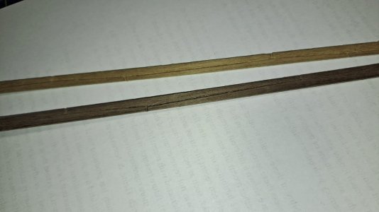
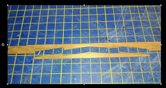
That is, you, knowing that main wales consists of two stripes, chose a 1x10mm strip. But you don't have to do that. You won't get two pieces, top and bottom, from the same strip. Your photo shows that the bottom piece worked, but the top one is a reject that needs to be thrown out.
Moreover, you are not taking into account the important fact that the stripes will have different lengths and bends due to the peculiarities of the body shape!
You basically can't have a single block. The ancient shipbuilders couldn't do that either, which is why they made four belts. You're wasting your time, effort, and money. You can't make two belts from a 10mm strip.
You don't need a 10mm wide strip. You need a 6mm wide strip. It's very simple.
I told you earlier: first, apply the design to the body (hull) of the model.
In the photo below.
Simply transfer this design to the model's body. Main wales and black strike are shown here. First, draw the borders, then the borders of the two belts, then the zigzags within the belts. It's that simple!

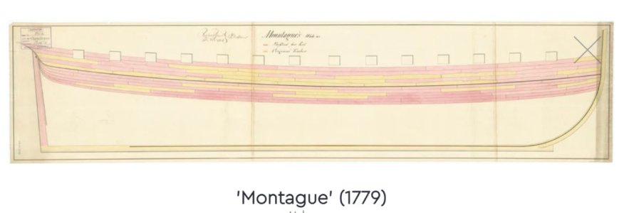
Then you make only one (the bottom!) piece from the 6mm wide strip. You take the dimensions and shape of this part directly from the drawing on the hull. As you make the part, you periodically place it against the drawing on the hull of the model. Use the drawing on the model body as a template. So, gradually, you first glue the bottom band. Then you make the matching top band, constantly adjusting the pieces to those already glued.
You'll make two belts, then the next two belts above them, one after the other. It's time-consuming, but it's high-quality and precise, and most importantly, simple and beautiful. Believe me, your original plan is too complicated and won't work.
According to calculations, the top of the piece is 6 mm, and its edges are 4 mm high. Therefore, the piece placed on top will add up to the required 10 mm.

See the photo below. I found photos of the method I described so you can see it clearly. I'll warn you right away that this isn't Agamemnon's model, and the modeler made a mistake here by using a "top and butt" technique. The modeler decided to work from the middle instead of from the bottom up, as I described, which is also interesting.
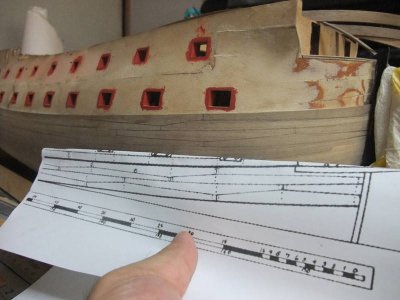
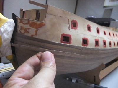
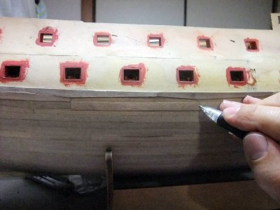
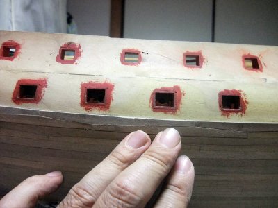
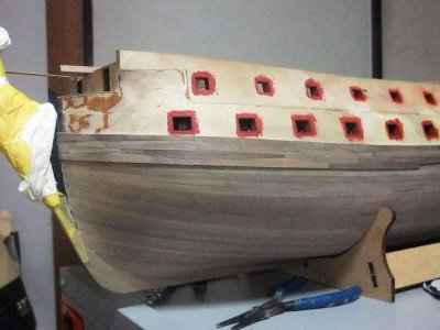
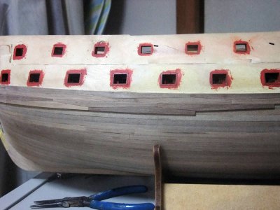
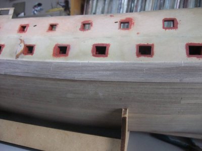
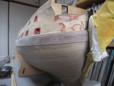

Can I use a 1 x 1 mm strip for the black strike?
Mark, the documents Allan found completely match the figures Brian Lavery showed for third-rank ships. That's good.
Unfortunately, none of us can tell you the millimeters, because the photos of the plans you sent me don't indicate the slat thicknesses. For convenience, let's assume your first finishing sheathing is made from 1 mm thick slats.
Let's start counting.
The hull planking thickness is measured from the frames. Your thickness calculations should take into account that one layer of planking has already been applied to the hull.
We know that the normal planking between the wales was actually 4 inches thick. For you it is 1 mm.
The thickness of the Main Wales was 8 and 1/2 inches.
This means that you need to make main wales from planks with a thickness of 1+ mm.
The black strike is exactly half the thickness between the regular sheathing and the velour, that is, you need to make the black strike from a 0.5 mm thick strip.
Just to be clear: "Black Strike" is an unofficial and later name, but it's used in Longridge's book, and you'll find it easier to find in this tome. Incidentally, this belt has nothing to do with the color black; it's just the name.
The width of the main wales was 4 feet 3 inches.
(4x12+3)x25,4/64=20,24mm
That is, you, knowing that main wales consists of two stripes, chose a 1x10mm strip. But you don't have to do that. You won't get two pieces, top and bottom, from the same strip. Your photo shows that the bottom piece worked, but the top one is a reject that needs to be thrown out.
Moreover, you are not taking into account the important fact that the stripes will have different lengths and bends due to the peculiarities of the body shape!
You basically can't have a single block. The ancient shipbuilders couldn't do that either, which is why they made four belts. You're wasting your time, effort, and money. You can't make two belts from a 10mm strip.
You don't need a 10mm wide strip. You need a 6mm wide strip. It's very simple.
I told you earlier: first, apply the design to the body (hull) of the model.
In the photo below.
Simply transfer this design to the model's body. Main wales and black strike are shown here. First, draw the borders, then the borders of the two belts, then the zigzags within the belts. It's that simple!


Then you make only one (the bottom!) piece from the 6mm wide strip. You take the dimensions and shape of this part directly from the drawing on the hull. As you make the part, you periodically place it against the drawing on the hull of the model. Use the drawing on the model body as a template. So, gradually, you first glue the bottom band. Then you make the matching top band, constantly adjusting the pieces to those already glued.
You'll make two belts, then the next two belts above them, one after the other. It's time-consuming, but it's high-quality and precise, and most importantly, simple and beautiful. Believe me, your original plan is too complicated and won't work.
According to calculations, the top of the piece is 6 mm, and its edges are 4 mm high. Therefore, the piece placed on top will add up to the required 10 mm.

See the photo below. I found photos of the method I described so you can see it clearly. I'll warn you right away that this isn't Agamemnon's model, and the modeler made a mistake here by using a "top and butt" technique. The modeler decided to work from the middle instead of from the bottom up, as I described, which is also interesting.


Last edited:
Let's continue the calculations. The channel wale, which Chris Watton called "upper wale" in the instructions, was 5 1/2 inches thick. This means the channel wale protruded just like the black strike. Therefore, you need to make it from 0.5 mm thick planks.
I have already said that the channel wale consisted of three belts. The channel wall's width was 2 feet 9 inches. This is 13 mm in 1/64 scale. However, it's better to calculate the width directly on the model, comparing it with the archival drawing. The problem is that the ship's sides are very heavily raked, and the figure is unlikely to be accurate. That's why Allan's document specifies the width perpendicularly and for each of the three bands. The width of each of the three bands specified in the document is 10 inches, which is 4 mm in 1/64. But this is perpendicular, which is why 4 + 4 + 4 = 12 mm is a full 1 mm less than the true size. You'd better use 4.5mm wide planks.
(Perhaps it is because of this nuance that the dimensions are given for a perpendicular that Chris Watton makes the channel wales so narrow on all his models?)
I think I understood the whole.Let's continue the calculations. The channel wale, which Chris Watton called "upper wale" in the instructions, was 5 1/2 inches thick. This means the channel wale protruded just like the black strike. Therefore, you need to make it from 0.5 mm thick planks.
I have already said that the channel wale consisted of three belts. The channel wall's width was 2 feet 9 inches. This is 13 mm in 1/64 scale. However, it's better to calculate the width directly on the model, comparing it with the archival drawing. The problem is that the ship's sides are very heavily raked, and the figure is unlikely to be accurate. That's why Allan's document specifies the width perpendicularly and for each of the three bands. The width of each of the three bands specified in the document is 10 inches, which is 4 mm in 1/64. But this is perpendicular, which is why 4 + 4 + 4 = 12 mm is a full 1 mm less than the true size. You'd better use 4.5mm wide planks.
(Perhaps it is because of this nuance that the dimensions are given for a perpendicular that Chris Watton makes the channel wales so narrow on all his models?)
But, in order to avoid mistakes: the thickness of the black strike is 0,5mm (this one above the main wale) but what would be the wide of the black strike (eg 5 mm, 4 mm, 6 mm ?????)
But, in order to avoid mistakes: the thickness of the black strike is 0,5mm (this one above the main wale) but what would be the wide of the black strike (eg 5 mm, 4 mm, 6 mm

At 1:64 scale the main wale would be a little over 3mm thick and the black strake would be about 2.6 thick and 4.8mm broad. The thickness of the next strake above the black strake is also given.
Allan
Last edited:


