• Ships of Scale has incorportated an extra level of security when you log In. Please follow on-screen prompts to acknowledge that you are not a robot via a "Check Box" or a "Pictorial Check Box Puzzle". This is needed due to higher level of AI Activity Security.
  • SUBSCRIBE TO SHIPS IN SCALE TODAY!

    The beloved Ships in Scale Magazine is back and charting a new course for 2026!
    Discover new skills, new techniques, and new inspirations in every issue.

    NOTE THAT OUR NEXT ISSUE WILL BE July/August 2026
  • Win a Free Custom Engraved Brass Coin!!!
    As a way to introduce our brass coins to the community, we will raffle off a free coin during the month of August. Follow link ABOVE for instructions for entering.

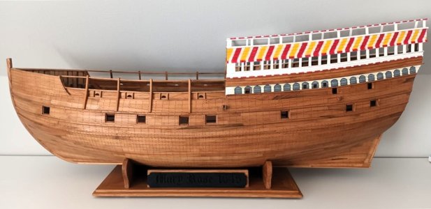
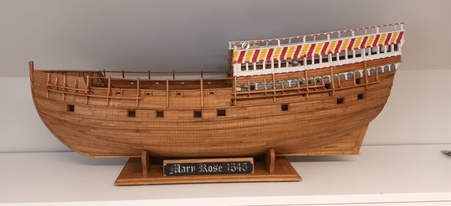
Mary Rose "Your Noblest Shippe" 1545 scale 1/50

Sharp Bow: it’s interesting that paintings of these old ships, often those made in the Nineteenth Century, and older ship model kits represent these Sixteenth Century warships with bluff bows and very full hull forms. Maritime archeology studies of actual vessels shows fine lined sharp bow hull forms. Examples include Mary Rose, the Newport ship and the Red Bay Galleon. Two out of three of these examples are of Basque construction. This puts the Spanish Armada stereotype of lumbering tubs to doubt. Actually what appears is a “boat like” lower hull form with massive upper works added on.

Examination of her hull form also sheds light on her catastrophic loss. Initial stability is an exponential function of the area of the vessel’s water plane. (The area enclosed by the waterline at which she floats). Vessels with poor initial stability heel easily until the change in water plane area stops it. They, therefore, do not necessarily capsize. Mary Rose, however, was apparently sailing with open gunports, and when she heeled to the point where she exposed one of these then loss of buoyancy and the effect of water sloshing back and forth in her lower hull caused her to capsize and sink.

It would seem that the blame lies with dockyard officials who decided to add gunports low in the hull that were necessary for large bore guns to a hull not originally intended to carry them. In their defense the concept of initial stability would not be known for another two hundred years.

Roger
 
Sharp Bow: it’s interesting that paintings of these old ships, often those made in the Nineteenth Century, and older ship model kits represent these Sixteenth Century warships with bluff bows and very full hull forms. Maritime archeology studies of actual vessels shows fine lined sharp bow hull forms. Examples include Mary Rose, the Newport ship and the Red Bay Galleon. Two out of three of these examples are of Basque construction. This puts the Spanish Armada stereotype of lumbering tubs to doubt. Actually what appears is a “boat like” lower hull form with massive upper works added on.

Examination of her hull form also sheds light on her catastrophic loss. Initial stability is an exponential function of the area of the vessel’s water plane. (The area enclosed by the waterline at which she floats). Vessels with poor initial stability heel easily until the change in water plane area stops it. They, therefore, do not necessarily capsize. Mary Rose, however, was apparently sailing with open gunports, and when she heeled to the point where she exposed one of these then loss of buoyancy and the effect of water sloshing back and forth in her lower hull caused her to capsize and sink.

It would seem that the blame lies with dockyard officials who decided to add gunports low in the hull that were necessary for large bore guns to a hull not originally intended to carry them. In their defense the concept of initial stability would not be known for another two hundred years.

Roger
Thanks Roger, this explanation saves me a lot of Google Translate work.

Also, don't forget that the gun ports were not operated by the cannon crew themselves, but by someone on the deck above.
Communication was done by shouting through openings in the deck...
 
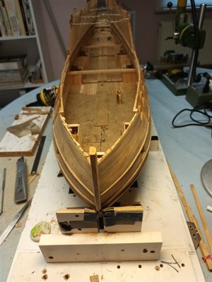
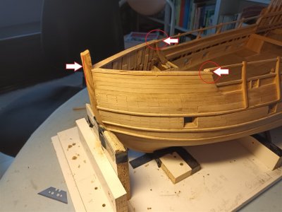
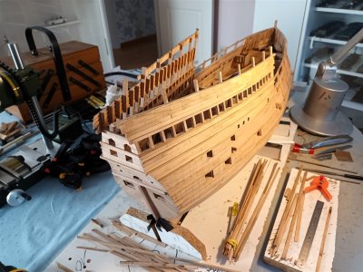
Planking the bow.
Purely speculative. The planking here is horizontal; on many carracks it is curved vertical, but at the time of the sinking of the Mary Rose this seems to be becoming somewhat old-fashioned. Most drawings then show horizontal planking.

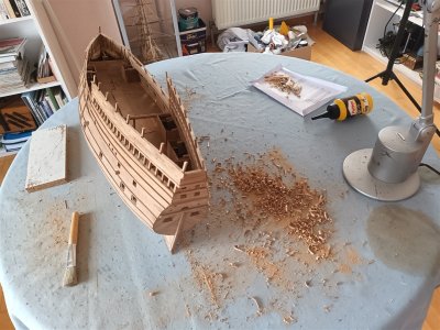
First " a clean up" of the inside
20240505_112213_1280.jpg
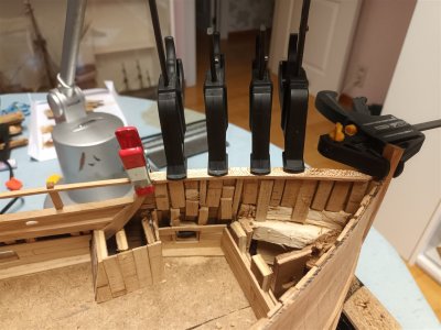
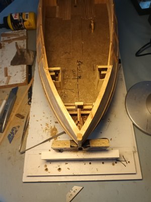
And step by step, the bow is being built up.
20240505_112223_1280.jpg20240506_150921_1280.jpg20240517_192235_1280.jpg20240517_192250_1280.jpg20240517_195815_1280.jpg20240520_082311_1280.jpg20240520_082322_1280.jpg
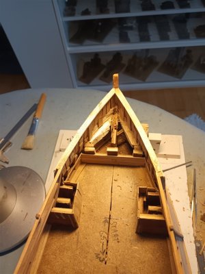
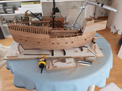
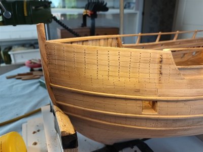
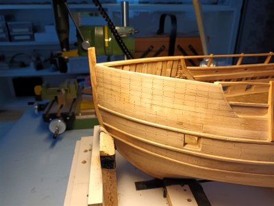
The planking of the bow is finished. It is not clearly visible in the photos, but there are still some dips and dips in the shape here and there. However, the planks are thick enough to sand away these irregularities.
So still sanding, inserting treenails into the planks, etc. to do.

Not happy with the blunders on the right, but fortunately we won't see any of that later. And still needs further sanding (left).
20240520_082348_1280.jpg
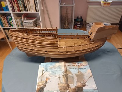
With the cardboard front castle. In this new setup, the height of this castle has already decreased by 1.5 cm.
20240520_084425_1280.jpg
 
Last edited:
The planking at the bow has been further sanded and fitted with treenails.
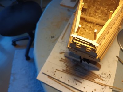
20240523_190250_1280.jpg20240529_073253_1280.jpg
Back to the rear castle.
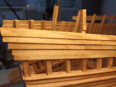
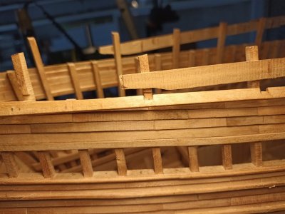
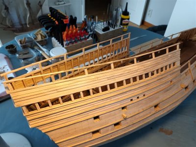
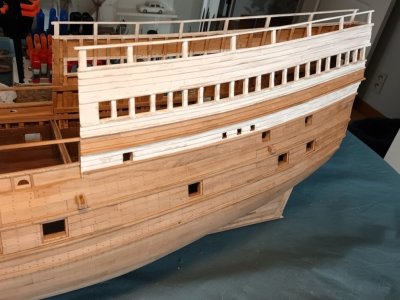
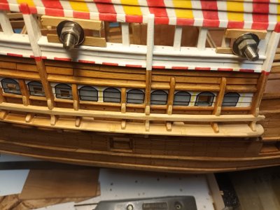
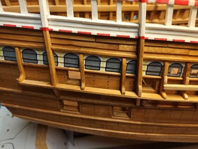
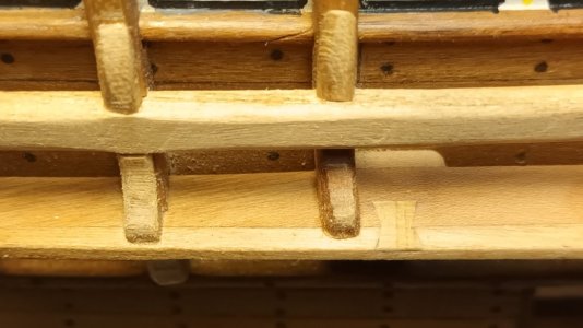
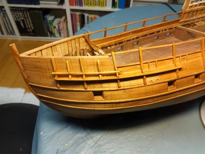
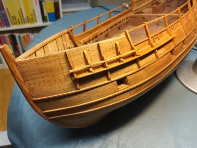
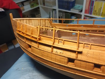
Smallerwales are placed on the clinker planking. Naturally, none of these have the same dimensions.
The drawings and photos are consulted partly to determine the "correct" position. The spacing between the wales was also already taken into account for future painting work.
20240528_201640_1280.jpg
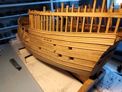
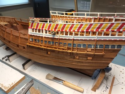
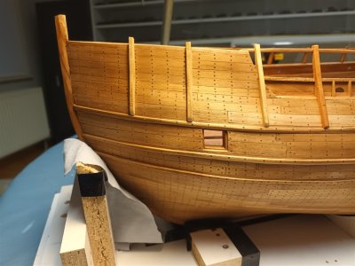
All wales are installed on the clinker-built planking.
20240603_191535_1280.jpg
On the starboard side, the beam has been replicated on which the swivel cannons will later be mounted.
20240603_191513_1280.jpg
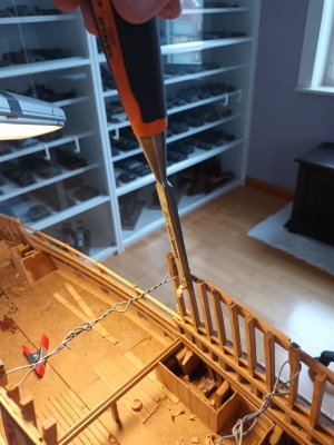
And the frames are to thick, they must be thinned
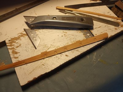
First a pencil line.
20240603_184350_1280.jpg
Then "heavy material" deployed cautiously, of course.
20240603_184516_1280.jpg
One side is reduced from 6 to 5 mm; the intention is to later make the frames above the beam of the pivot bearings even thinner to 4 or, if possible, 3 mm.
20240605_095738_1280.jpg
 
Last edited:
With the beam for the port side swivels also installed and the frames thinned, it is time to continue working on the transom.
The clinkerplanking that was installed initially has been removed.
20240610_162150_1280.jpg
The intention is to install two cannons here; the openings of the "swivels" will then remain empty.
Installing the same number of cannons as the Anthony drawing is not feasible. It is a beautiful drawing to show to a king, but in reality, this is not a practical design.
Various attempts...
20240612_154155_1280.jpg20240612_160611_1280.jpg20240612_160922_1280.jpg
And in the end, this is what it turned out to be (so attempt 3).
20240614_075816_1280.jpg
Then finish the holes for the struts on the port and starboard sides with a beam at the top.
First, grooves are made.
20240612_163947_1280.jpg20240612_163935_1280.jpg
This is more work, but positioning the beam correctly becomes much easier.
And above this, clinker planking returns. This will provide more strength to the structure when the frames are made thinner later.
20240614_080016_1280.jpg20240614_095739_1280.jpg
 
Last edited:
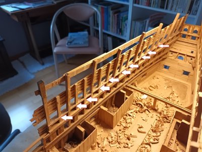
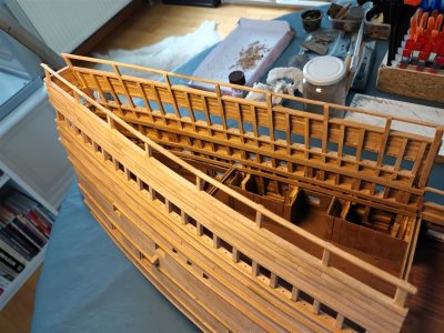
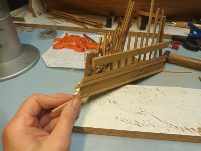
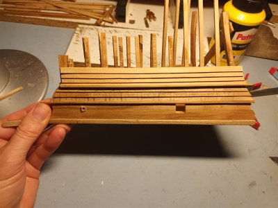
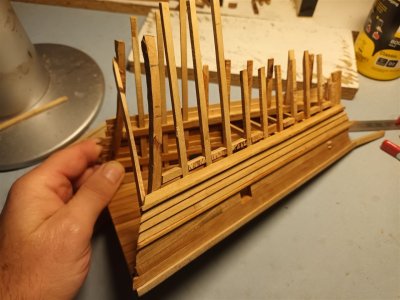
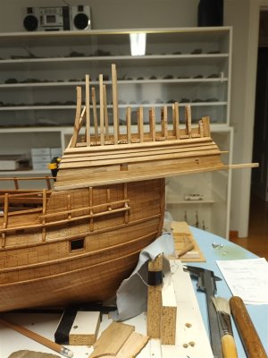
The frames of the upper deck.

Logically seen and thinking.
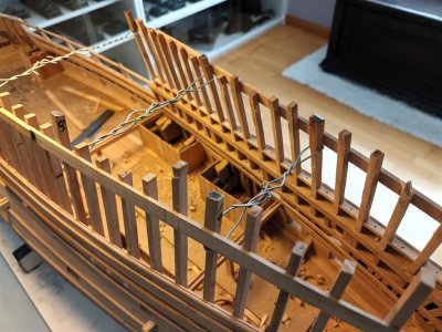
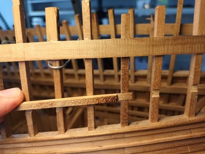
This bulwark is constructed with a section of planking and a section of shields. In accordance with the mid-deck, which also has partial shields, why should all the frames extend all the way to the top? If their sole purpose is to hold up a beam from which shields hang?
Therefore, the height of the majority of the frames extends only to the planking. And a few go higher; the distance between these frames is approximately in accordance with that of the mid-deck.

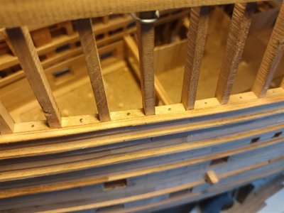
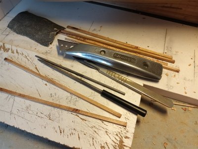
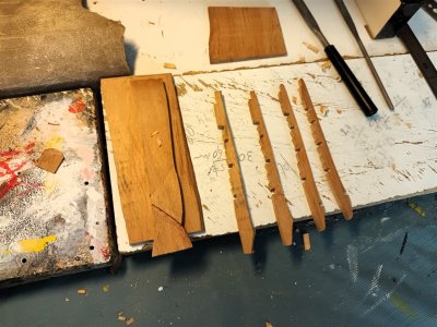
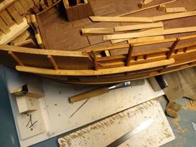
Saw off the frames to height and then narrow them to 3mm with a chisel and rasp.
20240619_191350_1280.jpg20240621_184102_1280.jpg
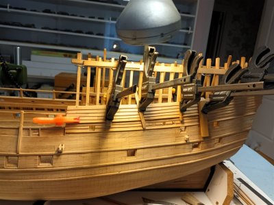
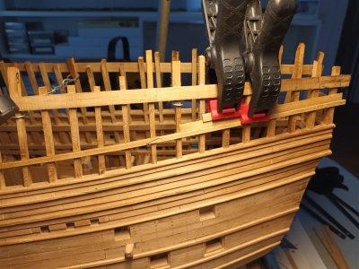
A beam is glued above the overlapping planking. The connections are solely to maintain sufficient strength on the model.
20240621_190535_1280.jpg20240621_192222_1280.jpg
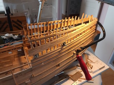
Then the longest frames are narrowed and brought up to height. This height is speculative; the shortest frame was the measure (little other choice).
20240628_193314_1280.jpg
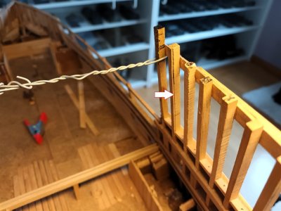
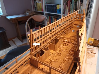
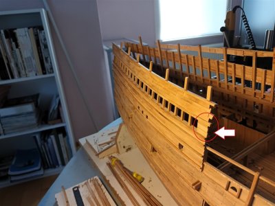
Starboard is finished, only a small beam remains to be attached at the top, and a little extra planking has been added (arrow).
20240628_193347_1280.jpg20240628_193404_1280.jpg
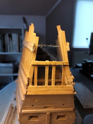
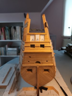
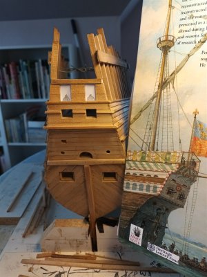
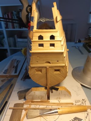
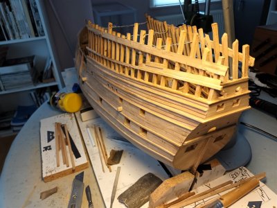
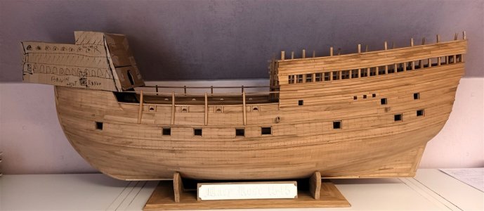
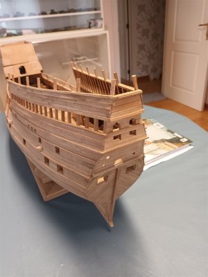
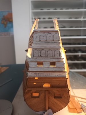
With all the frames thinned and the last planks attached to the transom, the rough shape of the hull and the aftcastle is largely complete.
20240701_205752_1280.jpg
A whole lot of wood chips. And the first pot of PVA glue is empty.
The workbench has been cleared for a moment. With paint cans visible in the background, it is time for some freshening up of the hobby room first.
20240702_164337_1280.jpg
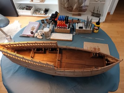
status with a cardboard fore castle
20240702_191045_1280.jpg20240702_191228_1280.jpg20240702_191101_1280.jpg
 
Last edited:
Mary Rose was then a little time on hold.
Repainted and reorganished the hobby room. Now also with a small stereo that produces a truly old-fashioned sound. 40 years old...
20240717_185003.jpg


20240717_185028.jpg


Everything in order, no more searching for tools
20240717_185503.jpg


And cleaning of the military collection. About 1450 models...
20240717_185349.jpg
 
With the room completely cleaned, repainted, and reorganized, and a clean military collection. There was time for Mary again.
The gun deck is fitted with planks where the stairs will go. And it has received a coat of diluted and polished Tamya paint.
Later, little or nothing of all this will be visible.
20240730_152300_1280.jpg
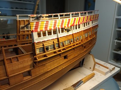
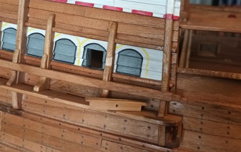
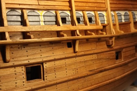
The railing of the top deck is finished.
20240730_152326_1280.jpg20240730_152336_1280.jpg
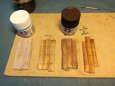
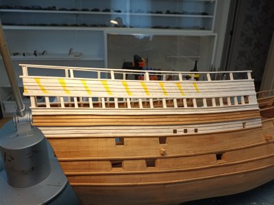
Color test for the hull.
It is not known for certain whether the original ship was white below the waterline. It is possible, but it has never been investigated further.
To get the maximum effect from the treenails, oil will be applied to the hull. I had some walnut oil left over as a test. Much better than the very diluted Tamya paints.
Walnut oil gives a beautiful result on wood, but you have to finish and repeat the treatment.
So it will be Danish oil
20240729_133546_1280.jpg
No comment
20240820_193553_1280.jpg
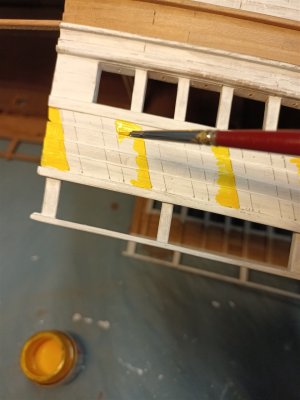
Applying masking tape to overlapping planking is not practical.
And, they didn't have masking tape back then in the 16th century either... So everything is marked out and painted "freehand".
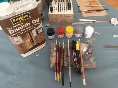
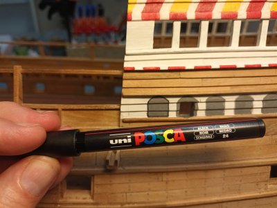
Materials used: Tamiya paint, paint markers, and Danish oil.
20240825_130449_1280.jpg
If you are right-handed, it is easiest to always paint the left line.
20240801_112645_1280.jpg
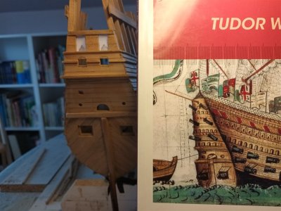
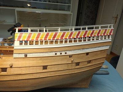
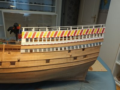
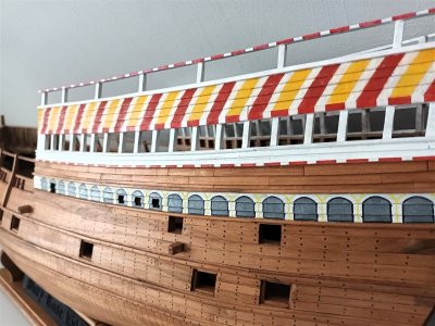
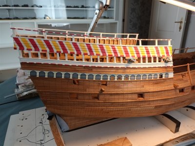
The colors are applied step by step. The book cover serves as a guide, but was not followed completely.
Port serves as the test side. So starboard still needs to be done.
20240731_115114_1280.jpg20240801_112220_1280.jpg20240821_204705_1280.jpg20240823_125635_1280.jpg20240823_125846_1280.jpg20240825_130607_1280.jpg
All "untreated" wood parts are finished with a layer of Danish oil.
No white below the waterline.
The original may have been painted white, or not.
Not a single ship on the Antony roll has a white underside.
This way, the treenails are most visible.
20240825_130654_1280.jpg
 
Last edited:
The starboard side is painted.
20240830_142457_1280.jpg
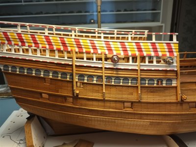
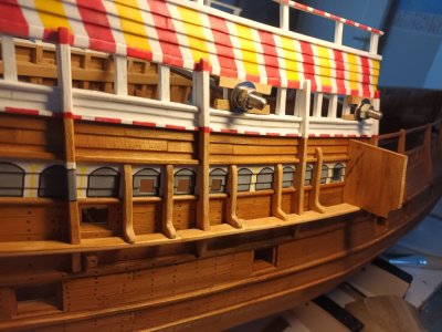
Now for the outer standards (a sort of extra frames as additional support for the rearcastle), quite a job of fitting and measuring...
20240901_093653_1280.jpg
dry fit
20240901_193341_1280.jpg

The color scheme on the transom just isn't working out. After 3 different schemes that didn't work.
A new start, with a schedule that will resemble the Anthony Roll more.
20240830_142512_1280.jpg20240902_152111_1280.jpg
The fourth attempt will be better...
After adding some extra wale, a sketch was made first.
20240903_093812_1280.jpg
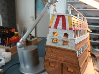
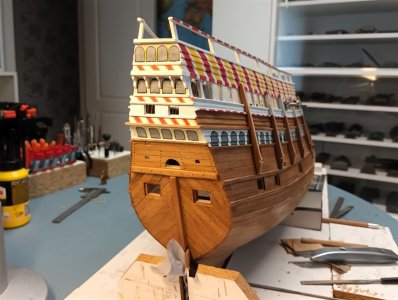
And this is the result, pretty okay I think, after 4 attempts...
20240906_124714_1280.jpg
 
Last edited:
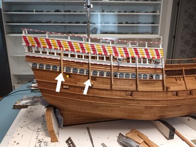
Moving on to the standards.
Not all standards match the paintwork :( Painter's mistake, says the carpenter....;)
20240906_124800_1280.jpg
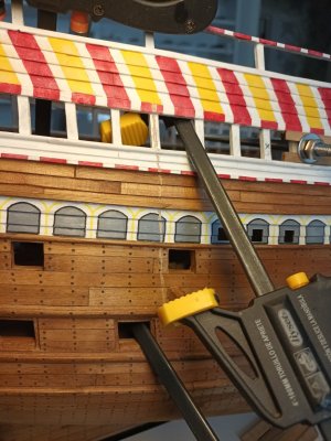
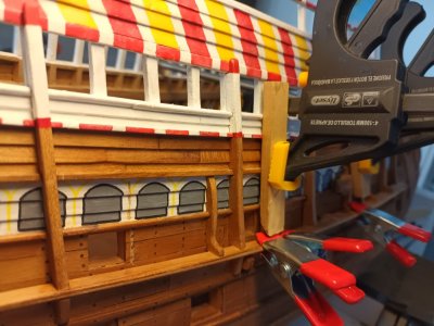
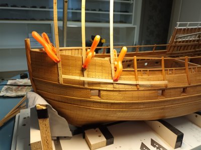
Painting in advance also has disadvantages if you need to glue.
20240907_092947.jpg
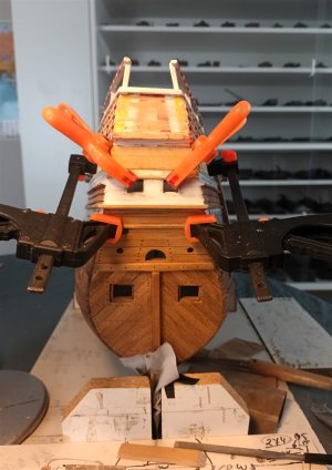
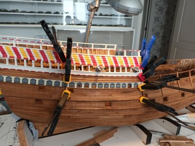
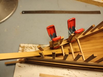
Clamps
20240907_095211.jpg
Constructing the "channel"
I have never seen such a long and narrow channel. Moreover, it only touches the hull itself in 2 places.
20240906_194935.jpg20240907_095226.jpg20240909_195203.jpg20240910_163734.jpg
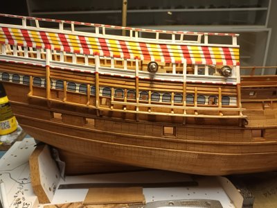
The channel has been installed, now to make the small stands and glue them in place.
20240912_170024.jpg20240914_165900.jpg
 
Last edited:
Now the same principle follows at the bow.

So, with virtually nothing remaining of this part of the ship, it becomes a matter of searching and thinking.
I already have a rough idea of what it's going to be. Now I just need to convey this to Mary Rose ;)
20241001_135926_1280.jpg
Before proceeding with the outer castle, a few smaller items were added first.
20241002_192118_1280.jpg20241010_152904_1280.jpg20241007_101556_1280.jpg
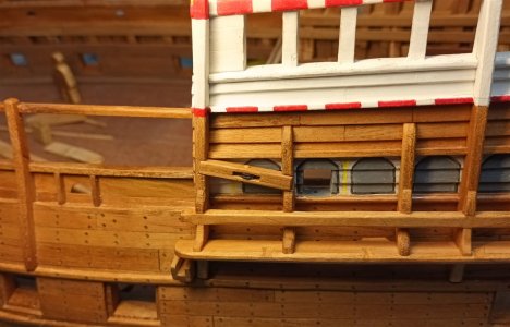
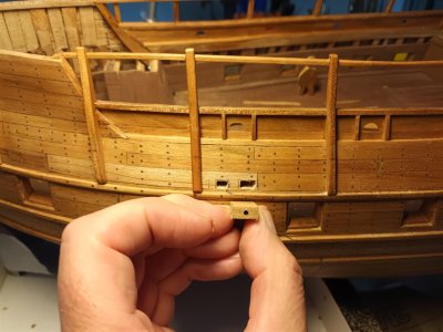
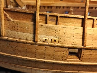
The starboard cabin at this location, a hole has been made through the hull here (purpose??)
So there is also one provided on the port side.
20241010_152925_1280.jpg
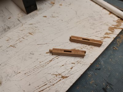
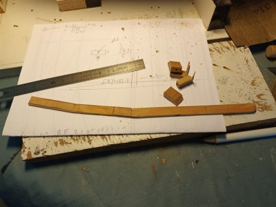
Preparation of a few more pieces
20241010_124314_1280.jpg
20241010_135353_1280.jpg20241010_152834_1280.jpg
With the rough shape of the channel of the foremast. It is made of 3 parts.
20241010_135338_1280.jpg
 
Last edited:
Great news! I've been following this construction project and was very sad to see it lost.
 
On each side, 3 "standards" are placed as a base for the rest and the "rigging rail".
20241002_192415_1280.jpg
My first impression of this tranquility
The right side should become narrower and would function as a rigging rail.
In the middle come the standing rigging (6)
And the left side should also be made narrower so that one of the two anchors can be attached to it.
20241010_191112_1280.jpg
Ideas and comments on this are always welcome.
Almost all the drawings contradict each other (even in the same book...), some have 2 rests stacked on top of each other here, others 1, but higher.
The main requirement is that there is sufficient space in relation to the forecastle to attach the ropework to it later without snagging.
The channels, with their accessories, on both sides of the bow are ready.
20241018_081443_1280.jpg20241018_081451_1280.jpg20241018_081502_1280.jpg
Status
20241018_103408_1280.jpg
 
Last edited:
Great news! I've been following this construction project and was very sad to see it lost.
Welcome back, Mary is NOT LOST but "under repair ;)

Further with Mary
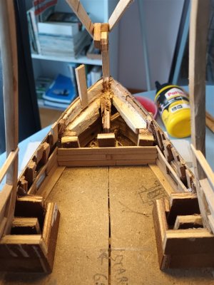
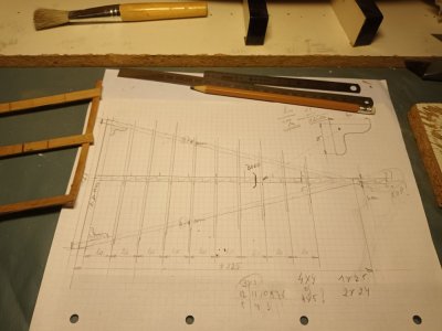
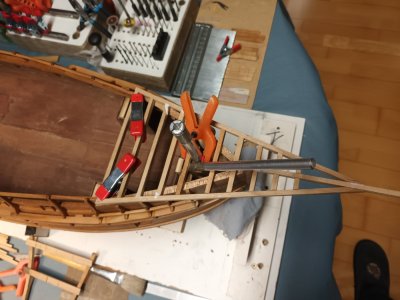
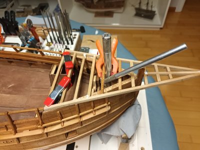
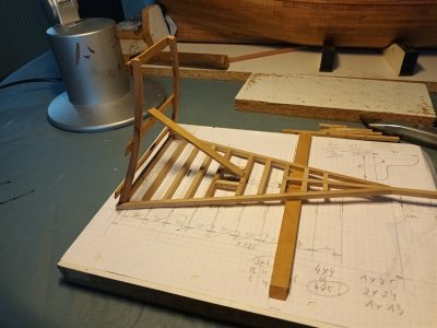
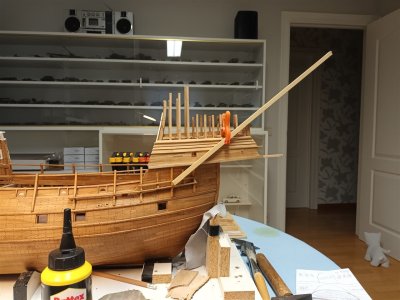
Below is a first idea of the lowest deck of the forecastle.
20241019_065817.jpg
The construction of the forecastle has only just begun and I am already making mistakes. There simply cannot be a beam in the middle, because then there is no room for the foremast...
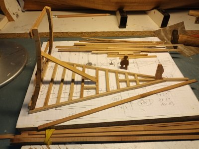
So a new plan without a beam in the middle.
After testing where the foremast and the bowsprit could be placed.
20241025_194211.jpg20241025_194218.jpg
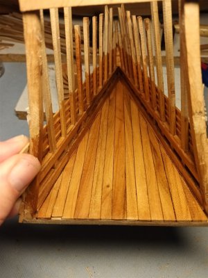
there a base of the forecastle with the curved sides glued to
20241028_163120_1280.jpg
Final check to make sure it is properly straight.
20241028_145001_1280.jpg
Everything is ready to start on the sides.
20241029_085958_1280.jpg
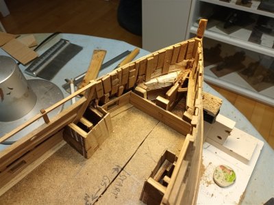
The planking of the front castle has started. At the bottom, there will first be 3 standard planks, followed by clinker planking above that.
20241030_183844_1280.jpg
Stock of sawn decking planks.
20241030_183906_1280.jpg
And the lowest deck is planked. This will be virtually invisible later, so I haven't put much time into it.
20241104_182321_1280.jpg
 
Last edited:
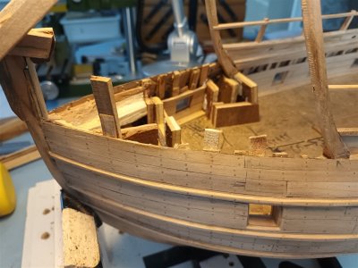
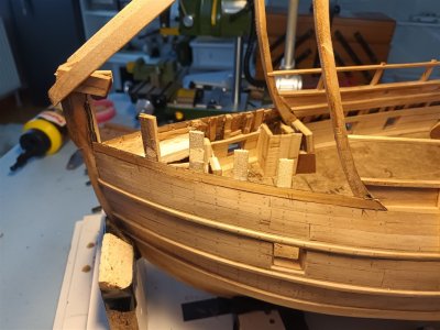
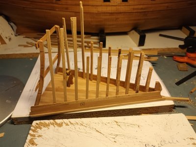
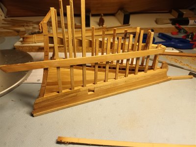
And now to put up the frames.
20241105_081019_1280.jpg
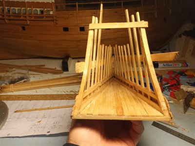
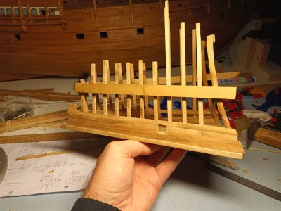
All the frames are in place
20241106_112734_1280.jpg20241106_112813_1280.jpg
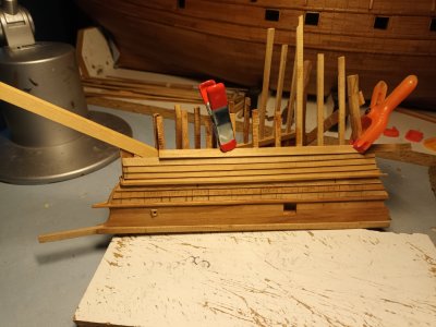
A temporary reinforcement has been placed at the top.
There is one gunport per side. On the Anthony Roll there are two, but that is very optimistic in my opinion. There is simply no room for them.
20241114_080708_1280.jpg
The interior finish will be executed in the same style as the rear castle.
20241114_080731_1280.jpg
The upper planking is also clinker style.
20241114_080746_1280.jpg20241115_182620_1280.jpg
 
Last edited:
Slow, but...
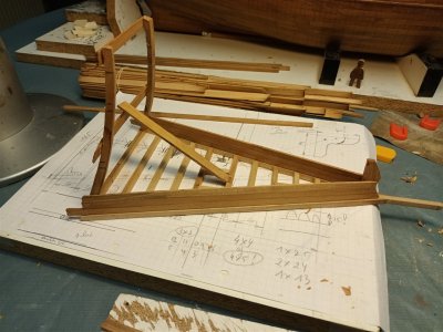
20241126_084348_1280.jpg20241126_084400_1280.jpg
20241126_084600_1280.jpg
The lowest deck is starting to become difficult to reach and has therefore already been treated with a layer of Danish oil.
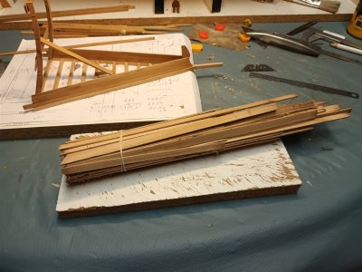
20241119_111908_1280.jpg
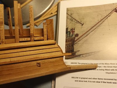
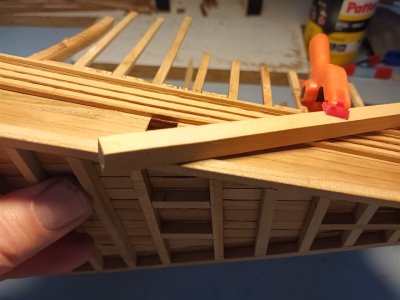
Almost forgotten, the bowsprit.
20241126_084311_1280.jpg
Roughly determine where this goes with a dummy
20241126_142442_1280.jpg
The correct angle is ??
20241126_160305_1280.jpg
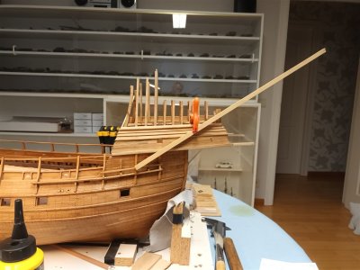
So something like that
20241126_160431_1280.jpg
Barely, but it fits.
20241127_092332.jpg
And has support.
20241127_093804.jpg
The shape of the forward section under the bowsprit still needs to be adjusted.
How exactly, I don't know yet.
 
Last edited:
Back
Top