• Ships of Scale has incorportated an extra level of security when you log In. Please follow on-screen prompts to acknowledge that you are not a robot via a "Check Box" or a "Pictorial Check Box Puzzle". This is needed due to higher level of AI Activity Security.
  • SUBSCRIBE TO SHIPS IN SCALE TODAY!

    The beloved Ships in Scale Magazine is back and charting a new course for 2026!
    Discover new skills, new techniques, and new inspirations in every issue.

    NOTE THAT OUR NEXT ISSUE WILL BE July/August 2026
  • Win a Free Custom Engraved Brass Coin!!!
    As a way to introduce our brass coins to the community, we will raffle off a free coin during the month of August. Follow link ABOVE for instructions for entering.

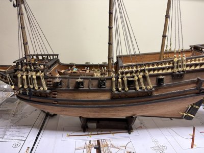
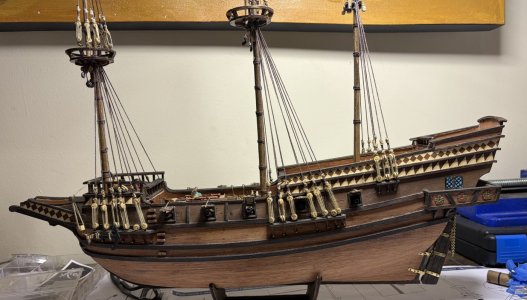
Buccaneer 1:100 by Occre - Build log

5/20/26 to 5/21/26
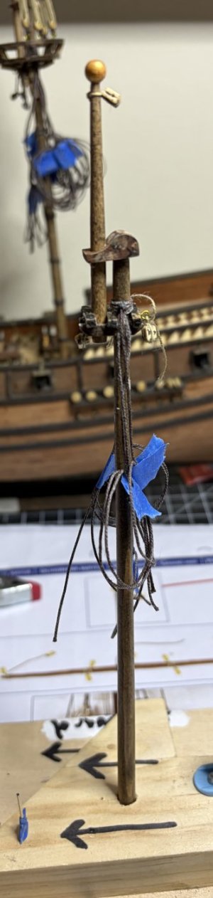
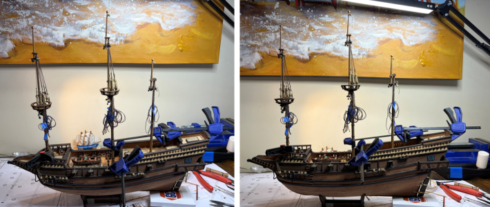
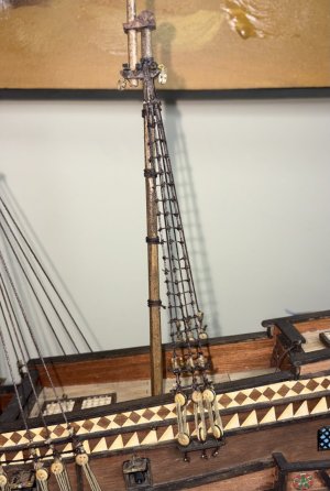
I will be building the mizzenmast in the same way as the foremast and mainmast, including building it off the ship as well as building it in sections.

Being the third mast, and all three have been pretty much the same, it goes together very quickly.

First there are only 2 sections. Second, I have made two others very recently. Third, I have learned from my previous mistakes.

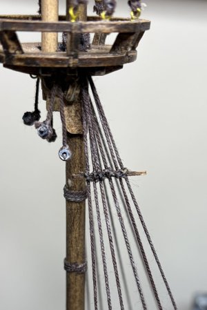
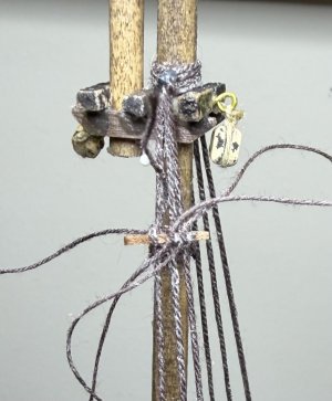
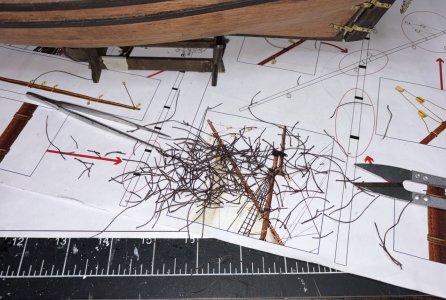
The top went together quickly and while it was drying, I seized the shrouds. There are six shrouds (two pairs and two shifters) off the mast and then with the mast head open, I placed them over the mast head and tightened them up. All shrouds were marked with which deadeyes they would go to.

The topmast was installed.
IMG_0731.jpeg
Very quick build. And then while writing this I realized that I forgot to put the four wooldings on. Argh. Not a difficult fix, but I hate it when I get moving faster than I should.

IMG_0753.jpeg
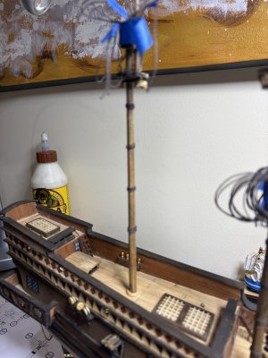
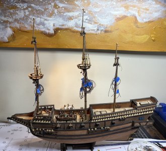
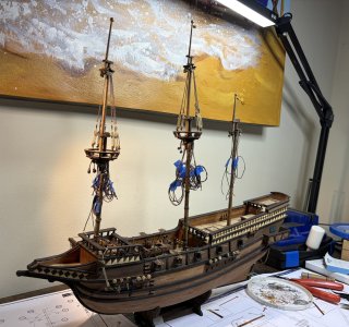
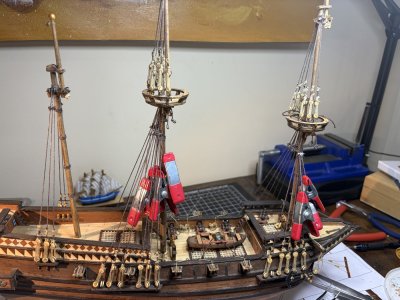
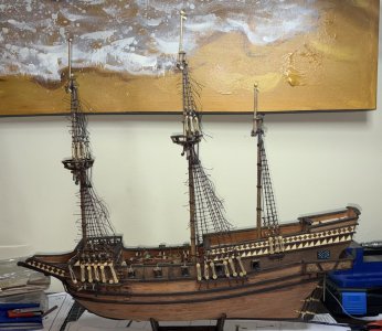
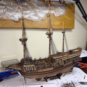
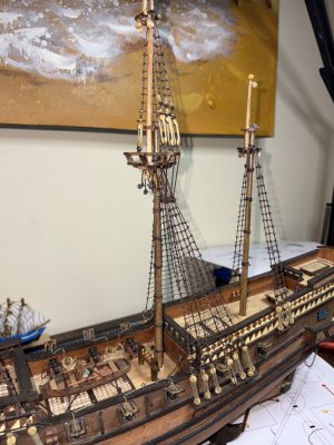
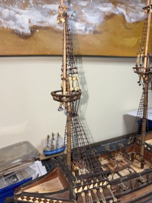
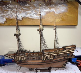
The masts are complete.
IMG_0732.jpeg

IMG_0734.jpeg

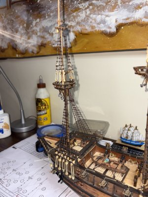
Next up… stepping the masts and the tying the lower shrouds.

Time for this portion: 4 hours
Total time to date: 295.5 hours
 
5/22/26 to 5/28/26
I will be carrying on with posting a less wordy and condensed build log but will attach the full unredacted build log as a pdf for those who want it.

I know I have been working on rigging for a little bit, but I am finally going to get to do what I envisioned as “rigging” when I picked up the hobby, when I purchased my Bluenose way back in October of 2000, and again when I started the hobby in earnest in March of 2023 (again with my Bluenose). That vision was of attaching lines from the top of the masts to the deck.

Over the past few years, I have learned that those lines are called shrouds and they do not attach to the top of the masts, nor do they attach directly to the deck.

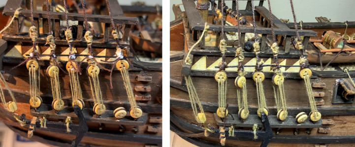
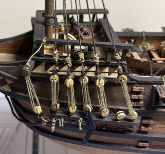
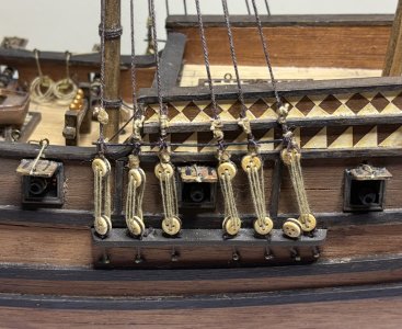
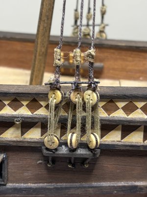
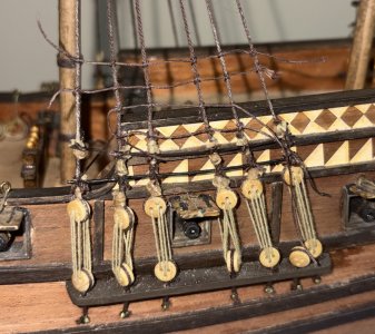
Today I attached the first two lower shrouds on both the starboard and port sides of my Molino to their respective deadeyes.

But let us take a step back as the first thing I did was step the three masts.

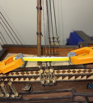
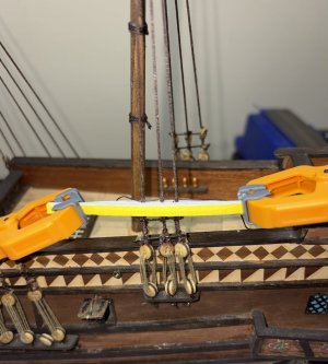
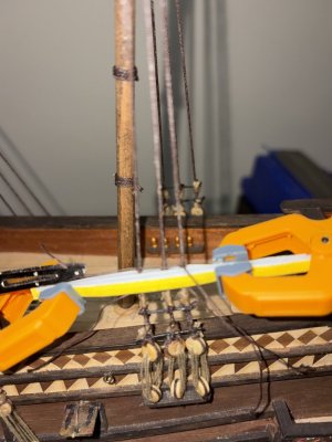
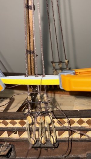
I glued them in place one by one aligning them both by themselves and in relation to the other masts. I used a couple of clamps to hold them in place while the glue dries.
07 combo1.png

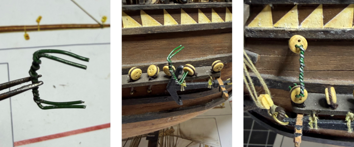
I decided to try twisting the wires together again. I had tried this previously, but it just did not work as there was a lot of play between the wires.

It took a few tries, but it worked. I now have the twisted wires “X” to hold the deadeyes apart. And they work much better than the single or double wires.
07 combo2.png

The process is fairly straightforward. It starts with the two foremost starboard deadeyes and then switches to the port side. This back-and-forth pattern continues through all the shroud pairs (and swifters) for all the masts.
07 combo3.png

07 combo4.png

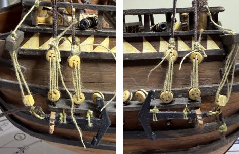
I took an extra step of putting a second seize on each shroud, slightly above the seize right at the deadeye.
IMG_0763.jpeg

IMG_0764.jpeg

Two key takeaways were:
  • Although stressed earlier, it makes life a whole lot easier if you have extra thread on the shrouds, seizes, and reeving. Short threads take a lot more time to tie than longer ones.
  • Remember the reeving pattern, and that the pattern on the starboard and port sides are mirror images of each other. Reeving always starts at the fore most lower hole of the upper deadeye.
Next up… the ratlines.

Time for this portion: 13.5 hours
Total time to date: 309 hours
 

Attachments

5/29/26 to 6/2/26

Finally the ratlines…

While prepping for the shrouds, I had seen a little information on the small boards on the shrouds directly above the upper deadeyes so I thought I would dig a bit deeper into what they are along with anything else associated with the ratlines.

Ouch, either that little research was a big mistake or a good thing as I found several items that are part of the shrouds/ratlines but were not included in the kit or the instructions. I am game for learning about ship design and construction and since the Molino is a fictional ship, I have complete artistic freedom over my build so instead of my planned jump into the ratlines, I will first be adding the following:
  • Sheer poles
  • Futtock staves
  • Catharpins
  • Futtock shrouds
  • Rat-boards (or shroud boards)
And then finally the rope ratlines.

I guess only time will tell if adding all of these was good decision or not.

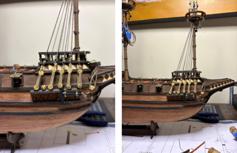
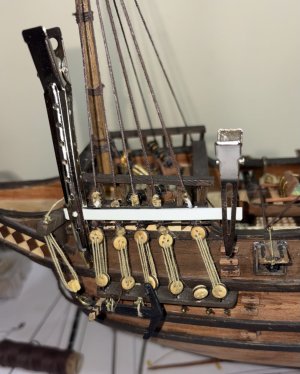
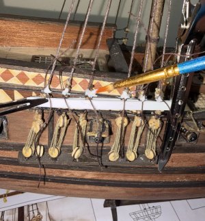
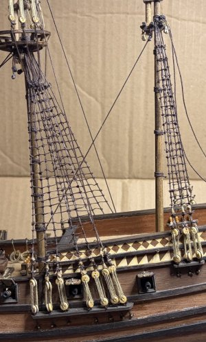
First up are the sheer poles which are considered the baseline anchor of the shrouds. They are installed directly above the upper deadeyes.

At scale they are only 0.5mm in diameter, so I am going to use some wire. After a little sanding and two coats of flat black paint, they are glued onto the seizes above upper deadeyes.

Once the glue dried, I tied a clove hitch topped with a half knot at each shroud/deadeye using small brown thread to simulate how the sheer pole was attached.

08 combo1.png

The sheer poles really helped with squaring up the deadeyes to the ship and kept them from spinning/twisting. So far or at least adding sheer poles look to be a genuinely nice add.

IMG_0774.jpeg

IMG_0772.jpeg

IMG_0773.jpeg
I was only able to do about half of the knots as we were heading back to the states for our first time after moving here. On our trip we will be splitting time between Colorado and North Carolina before returning here in early July. It will be great to see friends and family, but it will be a month away from the Molino.

I will finish up the knots on the sheer poles upon my return and then add the futtock staves and the catharpins.

Time for this portion: 3 hours
Total time to date: 312 hours
 
7/10/2026 to 7/18/2026

I will be carrying on with posting a less wordy and condensed build log but will attach the full unredacted build log as a pdf for those who want it.

Thirty-three days away from home and in the States. We have been back for almost a week, and I am finally at the point of working on my Molino.

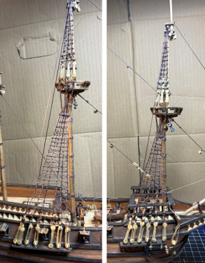
Next up are the futtock staves.

The futtock staves are made with 0.7mm x 0.7mm dark wood and will be tied to each shroud with a double overhand knot.

I use a thin brown thread (ran across beeswax) capped off with a drop of glue.
IMG_0945.jpeg
I have realized that because there are no shrouds above the top of the mizzenmast, there should not have been staves, but instead of cutting and removing them, I will leave them in place.
IMG_0943.jpeg

IMG_0946.jpeg

IMG_0949.jpeg
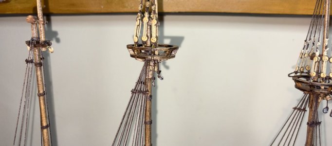
The catharpins brace the upper masts from extreme weather by pulling the lower shrouds inward (hence why there are none on this ship’s mizzenmast).

I will make mine using 0.5mm dark brown thread. The number of shrouds determines how many catharpins there should be. The foremast has 5 shrouds per side so it will have 3 catharpins while the mainmast has 6 shrouds meaning it will have 4 catharpins.

I tied one to the port side and topped it with a drop of glue and then ran the long end of each catharpin up and over the stave of the other side. I put a small clamp on each one to give it a little weight and the put a drop of glue on it. They are not yet tied, but once the glue is dried, the line will be taunt and should be easy to add a knot.
IMG_0950.jpeg
At this point I noticed that the foremast staves were not at the same height. I will not attempt to fix it but will use it as a learning experience for next time.

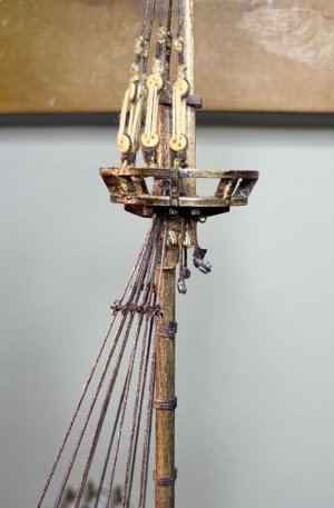
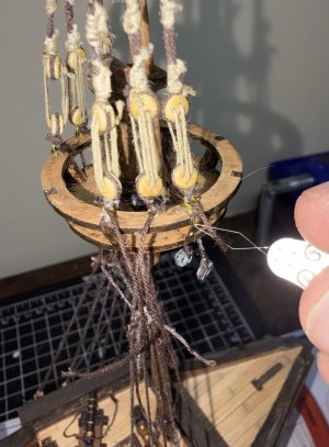
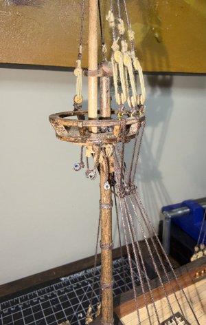
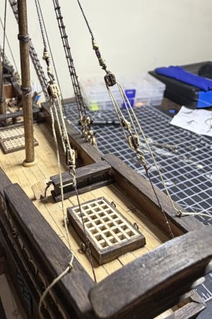
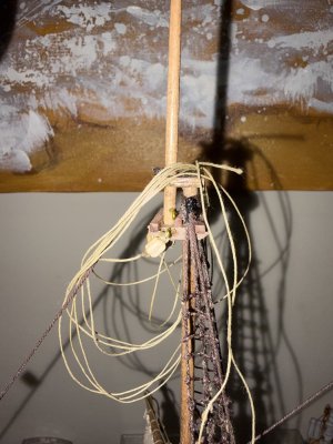
The futtock shrouds are supposed to connect the lower deadeyes to the staves and catharpins but on my kit, the deadeyes have already been connected to eyebolts attached to the top. To simulate the proper connection as best as possible, I tied a knot in a short piece of 0.5mm dark brown thread and feed it through the eyebolts using a needle threader, then routed the thread over the edge of the circular top, and down to the staves where it was tied off. Not perfect, but it looks nice.
IMG_0954.jpeg

IMG_0958.jpeg
I will have only one rat board (in addition to the sheer pole) at the bottom of each set of shrouds. They will be 3.7mm above the sheer poles. I will use 0.4mm x 0.4mm dark wood and tie them in place using 0.15mm dark brown thread.
IMG_0962.jpeg
Rat boards are used instead of rope ratlines because the shrouds spread widest near the deck, leaving too much unsupported space for a safe, comfortable foothold.
IMG_0978.jpeg
And now it is really time for the ratlines!

I am starting with the ratlines on the port side mizzenmast. It only has three shrouds per side. It will be a good first attempt.

I will be following a process a Rocky Mountain Shipwrights member detailed on Reddit a few months ago. He referenced a post on MSW, but it was posted by a “guest” several years ago, prior to MSW’s crash. I had unsuccessfully tried to reach out to the guest, so now I guess I will say it is from James Webster, and we've posted it on the club's YouTube channel.

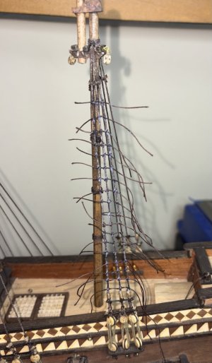
The process starts with two pieces of stock that are longer than the widest set of shrouds, and whose width is that of the desired spacing of the ratlines. Thin strips of sandpaper (around 200 grit) are glued to the pieces of stock. The pieces are placed on either side of the shrouds and held in place with light clips. The idea is that the sandpaper holds the shrouds in place and the width of the stock gives you a straight line to run the ratlines at the desired spacing.

The ratlines spacing on my Molino is between 3.3mm and 3.8mm and with a bit of good luck the sanding sticks I have are 3.6mm… perfect width. I cut a 220-grit stick in half and held them in place directly above the rat board.
IMG_0981.jpeg
This is a task that takes me back to 2000 when I bought my first model (Model Shipways Bluenose). In those days, I thought rigging was so amazing, and I thought ratlines WERE the rigging. This step was huge for me.

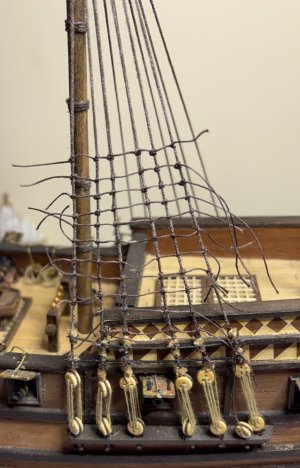
I held the thread and shakily tied my first clove hitch, then my second, and then my third and final one. I had done it… my first ratline. I removed the two pieces of stock and admired my first ratline. Yes, it looked like my first one as neither looked particularly good. I almost immediately decided to remove it and start over.
IMG_0982.jpeg
I put the pieces of stock back in place and tried again. My second attempt looked a lot better and I kept it. I then moved the pieces of stock up to sit on top of the first row and tied my second one. My speed and quality improved until about two hours later, the tying of the port side mizzenmast ratlines were done.
IMG_0983.jpeg

IMG_0983.jpeg

IMG_0984.jpeg

IMG_0985.jpeg

IMG_0989.jpeg
I diluted some white glue with water and used a paint brush to apply it to each of the 54 knots.
IMG_0992.jpeg
Once the glue was dried, I trimmed the tails. My first ratlines were complete.
IMG_0994.jpeg
One area I can improve on is that of holding the thread in place while tying the first knot of the ratline. I struggled with it and ended us using a light clip to hold the thread in place to the pieces of stock. It worked well and I removed it as soon as the first knot was tied, but I should be able to do it without the clip.

Time for this portion: 13 hours
Total time to date: 322 hours

 

Attachments

7/10/2026 to 7/18/2026

I will be carrying on with posting a less wordy and condensed build log but will attach the full unredacted build log as a pdf for those who want it.

Thirty-three days away from home and in the States. We have been back for almost a week, and I am finally at the point of working on my Molino.

Next up are the futtock staves.

The futtock staves are made with 0.7mm x 0.7mm dark wood and will be tied to each shroud with a double overhand knot.

I use a thin brown thread (ran across beeswax) capped off with a drop of glue.
View attachment 620452
I have realized that because there are no shrouds above the top of the mizzenmast, there should not have been staves, but instead of cutting and removing them, I will leave them in place.
View attachment 620453

View attachment 620454

View attachment 620455
The catharpins brace the upper masts from extreme weather by pulling the lower shrouds inward (hence why there are none on this ship’s mizzenmast).

I will make mine using 0.5mm dark brown thread. The number of shrouds determines how many catharpins there should be. The foremast has 5 shrouds per side so it will have 3 catharpins while the mainmast has 6 shrouds meaning it will have 4 catharpins.

I tied one to the port side and topped it with a drop of glue and then ran the long end of each catharpin up and over the stave of the other side. I put a small clamp on each one to give it a little weight and the put a drop of glue on it. They are not yet tied, but once the glue is dried, the line will be taunt and should be easy to add a knot.
View attachment 620456
At this point I noticed that the foremast staves were not at the same height. I will not attempt to fix it but will use it as a learning experience for next time.

The futtock shrouds are supposed to connect the lower deadeyes to the staves and catharpins but on my kit, the deadeyes have already been connected to eyebolts attached to the top. To simulate the proper connection as best as possible, I tied a knot in a short piece of 0.5mm dark brown thread and feed it through the eyebolts using a needle threader, then routed the thread over the edge of the circular top, and down to the staves where it was tied off. Not perfect, but it looks nice.
View attachment 620457

View attachment 620458
I will have only one rat board (in addition to the sheer pole) at the bottom of each set of shrouds. They will be 3.7mm above the sheer poles. I will use 0.4mm x 0.4mm dark wood and tie them in place using 0.15mm dark brown thread.
View attachment 620459
Rat boards are used instead of rope ratlines because the shrouds spread widest near the deck, leaving too much unsupported space for a safe, comfortable foothold.
View attachment 620460
And now it is really time for the ratlines!

I am starting with the ratlines on the port side mizzenmast. It only has three shrouds per side. It will be a good first attempt.

I will be following a process a Rocky Mountain Shipwrights member detailed on Reddit a few months ago. He referenced a post on MSW, but it was posted by a “guest” several years ago, prior to MSW’s crash. I had unsuccessfully tried to reach out to the guest, so now I guess I will say it is from James Webster, and we've posted it on the club's YouTube channel.

The process starts with two pieces of stock that are longer than the widest set of shrouds, and whose width is that of the desired spacing of the ratlines. Thin strips of sandpaper (around 200 grit) are glued to the pieces of stock. The pieces are placed on either side of the shrouds and held in place with light clips. The idea is that the sandpaper holds the shrouds in place and the width of the stock gives you a straight line to run the ratlines at the desired spacing.

The ratlines spacing on my Molino is between 3.3mm and 3.8mm and with a bit of good luck the sanding sticks I have are 3.6mm… perfect width. I cut a 220-grit stick in half and held them in place directly above the rat board.
View attachment 620461
This is a task that takes me back to 2000 when I bought my first model (Model Shipways Bluenose). In those days, I thought rigging was so amazing, and I thought ratlines WERE the rigging. This step was huge for me.

I held the thread and shakily tied my first clove hitch, then my second, and then my third and final one. I had done it… my first ratline. I removed the two pieces of stock and admired my first ratline. Yes, it looked like my first one as neither looked particularly good. I almost immediately decided to remove it and start over.
View attachment 620462
I put the pieces of stock back in place and tried again. My second attempt looked a lot better and I kept it. I then moved the pieces of stock up to sit on top of the first row and tied my second one. My speed and quality improved until about two hours later, the tying of the port side mizzenmast ratlines were done.
View attachment 620463

View attachment 620464

View attachment 620465

View attachment 620466

View attachment 620468
I diluted some white glue with water and used a paint brush to apply it to each of the 54 knots.
View attachment 620469
Once the glue was dried, I trimmed the tails. My first ratlines were complete.
View attachment 620470
One area I can improve on is that of holding the thread in place while tying the first knot of the ratline. I struggled with it and ended us using a light clip to hold the thread in place to the pieces of stock. It worked well and I removed it as soon as the first knot was tied, but I should be able to do it without the clip.

Time for this portion: 13 hours
Total time to date: 322 hours

Congrats Hugh on your first ratlines. Nicely done! Magic Mike
 
7/22/2026 to 7/28/2026

I will be carrying on with posting a less wordy and condensed build log but will attach the full unredacted build log as a pdf for those who want it.

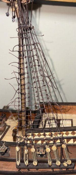
Next up is the mainmast port side ratlines. I will continue to work on (and hopefully improve on), holding the thread just to the front side of the first knot. As with the mizzenmast, I will hold the thread using a small clip.
IMG_1011.jpeg
An upgrade I will be doing is that on the larger masts (mainmast and foremast), I will not be running the ratlines across all the shrouds on the first two and last two rows. Instead, I will be skipping the outer most shrouds as it is more historically accurate on Spanish galleons of the 17th and 18th centuries to create a tapered look to the ratlines.
IMG_1012.jpg

IMG_1020.jpeg

IMG_1021.jpeg

IMG_1032.jpeg

IMG_1023.jpeg

IMG_1030.jpeg

IMG_1028.jpeg

IMG_1029.jpeg

IMG_1024.jpeg


Next up, the bowsprit and the stays.

Time for this portion: 12 hours
Total time to date: 334 hours
 

Attachments

7/28/2026 to 8/7/2026

I will be carrying on with posting a less wordy and condensed build log but will attach the full unredacted build log as a pdf for those who want it.

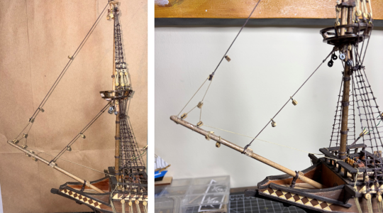
Next up is lashing down the bowsprit.
IMG_1215.jpeg
The base of the bowsprit is inserted into the hole, and the gammoning lashing is created with a piece of 0.5mm dark brown thread.
IMG_1214.jpeg
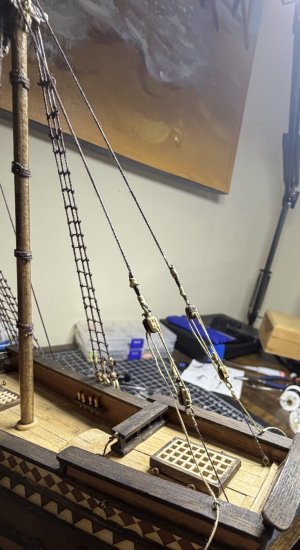
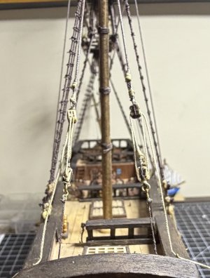
There are five fore stays and three pairs of back stays. All the stays will all be made with 0.5mm dark brown thread. Three of the fore stays will have two double blocks tied to them and one will have one double block. The mizzenmast mast forestay is the only one that does not have a block. There are no blocks on any of the back stays.

Just as I have done in the past, all the blocks will be sanded and given a coat of walnut stain.

The foremast lower stay runs from the top of the fore lower mast down to the middle section of the bowsprit. It has 2 double blocks on it. It is looped through the top (above/on top of the seized shrouds and tied about an inch down from the top.

There is not a lot of stuff on this mast, so looping the stay through the top is not too difficult but I can see why Ralph B, a friend from the Rocky Mountain Shipwrights, says to add the stays along with the shrouds when building the masts. Seize them at the top and then loop the tails up like I had done with the shrouds.

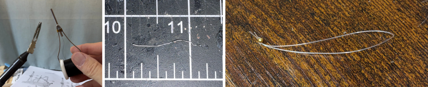
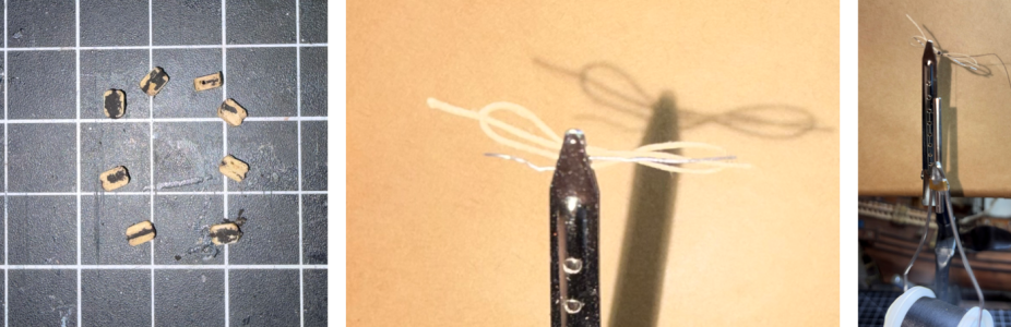
After this first stay and blocks, I decided to try something new. While I was back in Colorado, Ralph B showed me how to tie a figure eight strop using:
  • A vise holding a small clip
  • A very thin wire
  • A fly-tying bobbin (with thread)
  • A small loop of fishing line
strop combo1.png

IMG_1114.jpeg

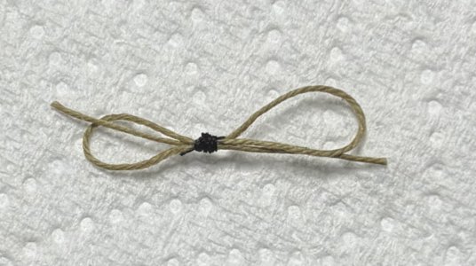
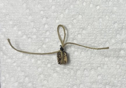
The remaining tails of the figure-eight strop will be trimmed later, but the strop is complete.

A block can be added to one of the loops by putting a block into the loop and tighten up the loop. An empty loop can be inserted over a yard and tightened as well.
IMG_1115.jpeg
The foremast topmast stay is next and gets two of the pre-made stropped double blocks installed on it.

A single block is tied to the end of the stay, leaving it about two inches short of reaching the bowsprit. The stay does not attach directly to the bowsprit, but rather through a series of four single blocks called a fore-topmast stay tackle or fore-topmast stay purchase.

The line that runs through the stay tackle gets tied off to the forecastle deck railing. At first, I thought that tying this off to the rail was another item in the “beginner kit” inventory, but on this age of ship (a 17th century Spanish galleon), tying things to the railing was common.
strop combo7.png
Once the stay is tightened, move the double blocks to the appropriate position and tighten up the strop and place a drop of white glue on the stay and on the seize.

The lower mainmast stay starts at is the top of the main lower mast and ends at a closed heart block. Two of the pre-made figure-eight double block strops are placed on the stay but again will not be tightened until the stay is in place.

This heart block is then laced to the other closed heart block which had been attached to the bottom of the foremast when I built the masts.
IMG_1217.jpeg
The upper mainmast stay goes from the main topmast to the cap of the fore lower mast. It will need one of the double block strops attached to it.

The last of the fore stays is on the mizzenmast, and it has only a single stay. It runs from the top of the mizzen lower mast top to the mainmast itself. It has no blocks.
IMG_1218.jpeg
And that wraps up the fore stays.

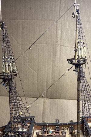
Next up are the back stays. The ship has a total of six of them, two on each mast.

The backstays of the foremast and mainmast (two for each mast) are connected from the top of the topmast to deadeyes on either side of the ship.

The four lower deadeyes are already in place as they were installed when the other deadeyes were installed onto the chain plates.

I reeved these deadeyes in much the same manner as I had previously done with a couple of differences.
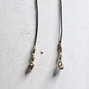
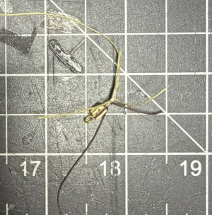
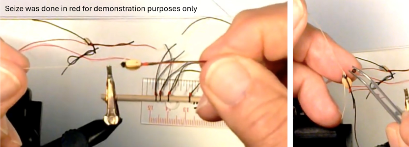
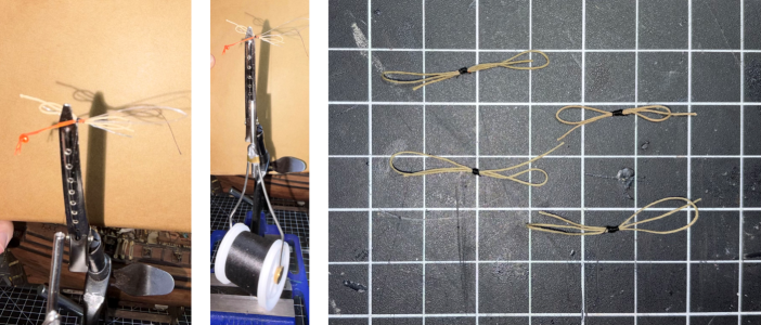
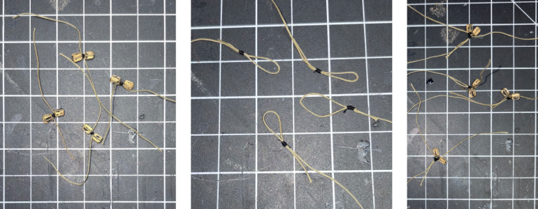
  • Instead of folding the tan seizing line in half, wrapping the tails around the shroud and tail, and then feeding the tails through the bight made when I folded the line in half (and doing this multiple times), I secured the tan seizing thread as close to the deadeye as possible with two half hitches. I then placed the looped fishing line (from making the figure-eight strops) over/parallel to the stay and tail and wrapped the line around the stay/tail and loop a few times. Then, much like the strops, I fed the seizing tail through the loop and gently pulled the loop down. A simple half hitch locked the seize.
  • This method gave me a lot smaller and tighter (I.E. better looking) seizes.
I created a second seize following the same process starting about 1/4” above the top of the first seize.

I do this for the back stays on the fore mast and the mainmast.
strop combo8.png
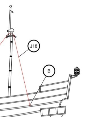
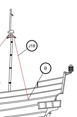
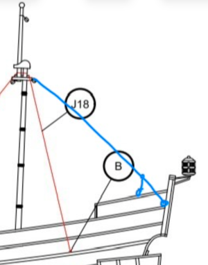
The back stays for the mizzenmast are supposed to go from the mizzenmast lower mast top to nails on either side of the ship, slightly behind the chainplates for the mizzenmast shrouds, J18 in the picture.
IMG_1130b.jpg
It just did not feel right to just run the back stays of the mizzenmast to a nail, so I used one of my remaining timeouts to do some research.

Next up, the back stays for the mizzenmast.

Time for this portion: 10 hours
Total time to date: 344 hours
 

Attachments

8/8/2026 to 8/16/2026

My research quickly told me I was correct in not feeling right about tying off the mizzenmast back stays to a nail.

I know the Buccaneer is more of a beginner kit, and I have been happy with it but have also been adding stuff to the build to give it more detail and realism. This too has added to my enjoyment of the build.

For a ship of this period (17th century Spanish galleon), the back stays for a mizzenmast with a lateen sail should be running back stays (also called flying or breast back stays), and to be period correct, they would be called burdas volantes (or simply burdas.)

The Molino should have burdas, but even with a fairly extensive online research, I have not found any good examples with pictures of what these would look like on a 17th century Spanish galleon, at least not of the lower connections near the deck.

Before I go further, a quick description of a flying backstay. Running backstays are temporary, adjustable backstays designed to support the mast against the forward pull of the sails. Unlike permanent standing backstays, they can be unhooked and swung out of the way to prevent the large boom or yards (or the Molino’s lateen sail) from running into them against them.

The only pictures I have found were for running backstays on either the foremast or mainmast. None for a mizzenmast.

I am sure I could find some diagrams in any number of books, but being in Mexico, my physical resources are reduced. Like many others, I write a lot of my build log after-the-fact. And as I was writing this portion, I thought of two more places for me to check.

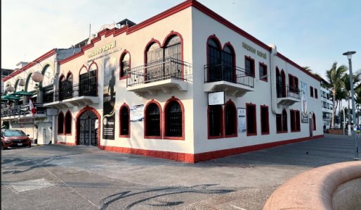
The first place is that the Mexican Naval Museums is about a 10-minute walk from my condo and it has ton of scale models. And even easier, I took pictures of all of them - at least all of them - when I was there about 2 years ago.
museum.jpg
A quick search through my pictures shows me that there are at least a few models that may have running backstays, but either the picture quality does not let me zoom in to see the details I am looking for, or the transom of the ship is just out of view. Looks like a trip to the museum is warranted.

I recently heard that the museum holds a special event on the last Saturday night of the month where there’s food and live music. Going this month will move up on my priority list, but it is about two weeks away.

The second place is the local public library. I know of one that is about 15 minutes away on a city bus. And like libraries in the states, anyone can come in and look. I have been wanting to investigate the library anyway, so this is another reason for me to finally go.
Biblioteca-Los-Mangos-2.jpg
And then while do more research online, I was pointed towards the Suburban Ship Modeler and his build of Bluenose. I am familiar with the site, as my other build is the Bluenose, but given I have not begun its rigging, I had not gotten that far in the Suburban Ship Modeler’s build. The Bluenose does not have a mizzenmast, but it has flying backstays. They are on the mainmast, and not on a lateen sail, but it is the closest thing to what I really want to see.
bluenose running backstays.png
I will run with modifying the Bluenose’s running backstays and put the museum and library on hold.

My thought is to replace the two backstays (J18) that are included in the kit to burdas. I am assuming the burdas would be somewhere near the blue line, and would have a couple of blocks, tackle, and hooks right near the transom on both sides.
IMG_1153.jpg IMG_1165.PNG
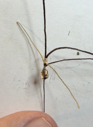
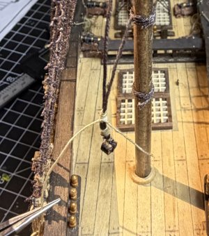
I will need to seize a double block onto the ends of the burdas, approximately 3/4 of the distance from the connection point at the mizzenmast’s top to the rear corners of the deck near the transom.

This double block will essentially split the burdas into a “Y,” with one leg of the “Y” going to a single block (with a ring seized to the downward side of the block) and the other leg going to an eyebolt that will be mounted on the cap rail, about an inch in front of the transom (this is the adjustable portion of the burdas). I will leave this line extra-long until I mount the sails as the direction of the wind and sails will determine which burdas will be taunt and which will be left slack. At that point I will determine how much of this extra line is needed to slack the line and make sure I have that much extra on the taunt side as well. The extra will be coiled up and hung or left on the deck.

The ring of the single block will be connected to a seized eyebolt/ring (using an “S” hook) to a connection point on the deck right up against the transom.

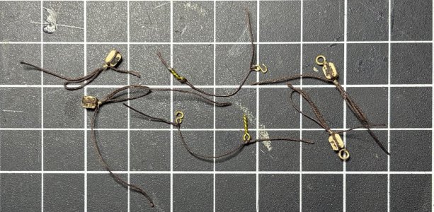
Here is what I need to make (all using the seized figure-eight strop that my friend Ralph taught me how to make):
  • 2 - single blocks with a ring seized to one end
  • 2 - double blocks
  • 2 - 1 1/4” line with an eyebolt on one end and an “S” hook on the other end.
IMG_1223.jpeg IMG_1225.jpeg

IMG_1230.jpeg IMG_1234.jpeg IMG_1235.jpeg

And just like that, my burdas are complete.
IMG_1237.jpeg

IMG_1238.jpeg

IMG_1239.jpeg

Onto the yards and running rigging.

Time for this portion: 6 hours
Total time to date: 350 hours
 
8/17/2026 to 8/22/2026

I will be carrying on with posting a less wordy and condensed build log but will attach the full unredacted build log as a pdf for those who want it.
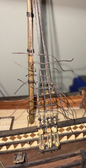
Onto the yards and running rigging.

My order will be different than what is shown and detailed in the instructions. I will be attaching the sails to each yard off the ship, then attaching the yards to the masts, and then finally I will be adding the running rigging. My work will also be on a sail-by-sail basis, from the bow of the ship back, and from the bottom up on each mast.

My planned order was:
  • Bowsprit
    • Spritsail yard
  • Foremast
    • Fore yard (lower yard)
    • Topsail yard
  • Mainmast
    • Main yard (lower yard)
    • Topsail yard
  • Mizzenmast
    • Lateen Yard
I have decided to have my sails fully bellowed at starboard brace (wind coming from the starboard).

Each yard and sail may have its own unique differences (like the spritsail should have water-holes or that the fore and main sails will have reef points), but once each yard and sail has been attached, I will be mixing in the running rigging list in the instructions.

Yowers, that is a lot of stuff that I have never done before, with my first attempt being the spritsail - not the biggest sail BUT the one sail that is up front and center… potentially the first sail to be looked at. A bit intimidating.

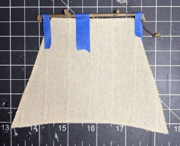
After taking a little time thinking about what I am undertaking, I decided to do the foremast topsail first, giving me a little practice before I go after the spritsail.

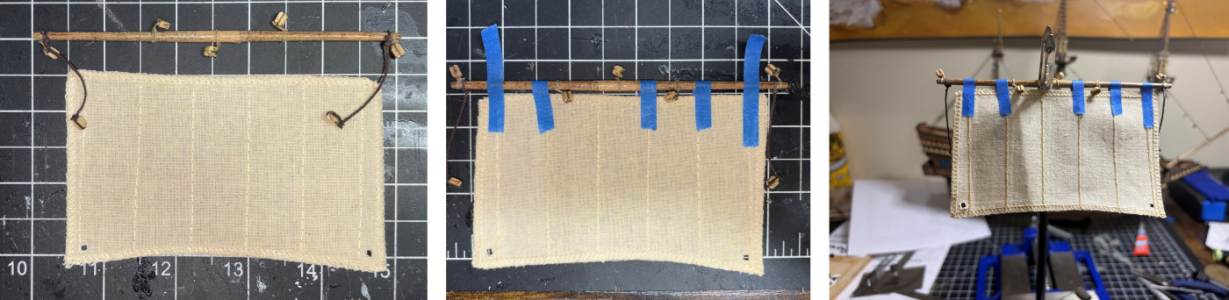
The yard is pinned.
IMG_1265.jpeg
The sails are temporarily held in place.
IMG_1266.jpeg
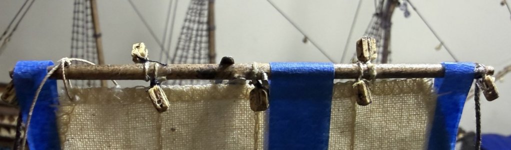
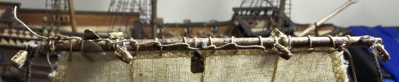
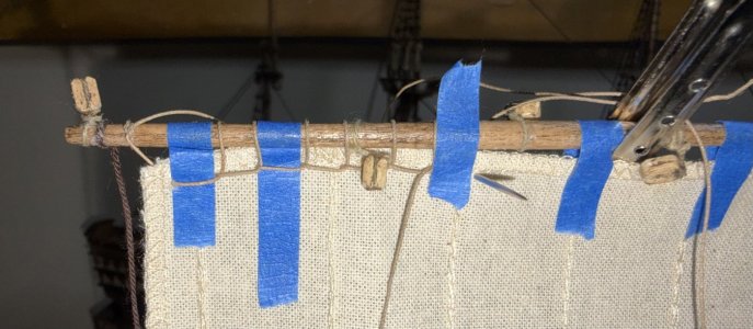
I decided to use Olha Batchvarov’s historical half-hitch spiral loops. They do not take much more time and look a lot better.
IMG_1267.jpeg
IMG_1268.jpeg
IMG_1269.jpeg

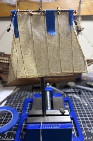
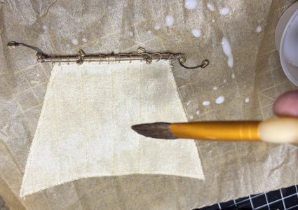
On a piece of wax paper, I use a big soft brush to drench the sail in a 50/50 mix of white glue and water.
IMG_1272.jpeg
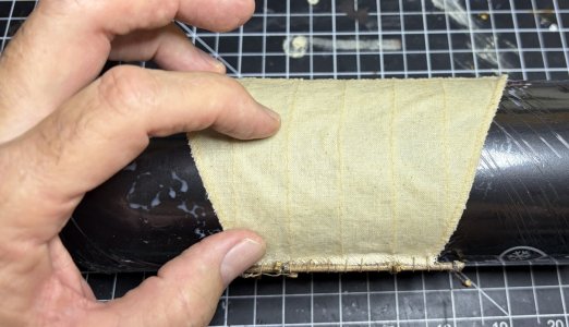
Put the wet sail “square” on the container, face up (this will put the hole for the pin “down” against the container; and hold the wet sail in place using your thumbs and middle fingers and use your index fingers to gently push/pull the center (top to bottom) of the yard towards the left (port).
IMG_1273.jpeg
Pinch the lower corners gently to give them a look like they are under stress (from the rigging).
IMG_1274.jpeg
IMG_1275.jpeg

Gently remove the sail from the wrapped container.
IMG_1281.jpeg
I really like the way it turned out and am excited about how the Molino will look.

When attaching the sail to the yard, I noticed that a couple of the blocks that I attached several months ago were attached in the wrong place. No idea how I did that, but I did. It was an easy fix, but required a fix nevertheless. I also removed the line near the center of the yard that was going to be used to hold the yard to the mast. Since I’m adding parrels, it will no longer be needed. That line will be removed from all of the yards.

At this point my practice is done. I still have to glue the pin in place, attach the yard to the mast, make, and install the parrel (and begin it is running rigging), but I will now go back to my planned sail order - the spritsail.

Time for this portion: 6 hours
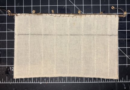
Total time to date: 356 hours
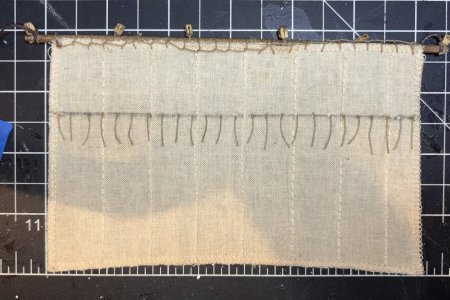
 

Attachments

8/22/2026 to 8/27/2026

Summary:
  • Starting the spritsail construction.
  • Identified a flaw in the kit:
  • Bowsprit too short; modified sail billow shape instead of replacing the bowsprit.
  • Detailed new construction methods for the fore lower sail, including reef bands/points, and installed the spritsail parrel.
  • Identified personal belaying error on the fore topmast stay-tackle.
  • Spent 10 hours on this phase, total time 366 hours.
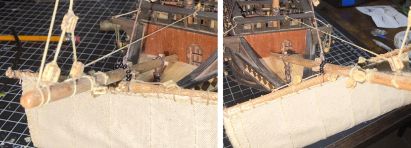
I will be carrying on with posting a less wordy and condensed build log but will attach the full unredacted build log as a pdf for those who want it.

I will now go back to my planned sail order - the spritsail.

Two differences from my sail test run. The spritsail has “water-holes” and I will be using a smaller gauge wire to pin the mast.

The water-holes are 2mm holes in the bottom corners of the sail. Since this sail is so close to the water, it needs a way to drain any water that gets on it. Think of them as scuppers for the sail.
IMG_1282.jpeg
The yard will be positioned at the bees which are at about the midway point of the bowsprit. To pin the yards, I will now be using a 0.6mm drill bit which is almost half the size of my original bit.
IMG_1283.jpeg
Picture1.png
IMG_1300.jpeg

The location of the yard just did not seem right as it was dead even with the tip of the beakhead, meaning the sail would be wrapped around it.

A quick ask of my AI friend Gemini revealed that the location is a known flaw in this kit. The bowsprit is too short. There are two ways to remedy it. I could remove and remake the bowsprit or I could modify the curve (billowing) of the sail. I went with modifying the billow.

Instead of a nice gentle curve, it must be a more drastic one.

The forward direction of the billow moves the sail away from the beakhead and with the drastic curve, it will still look like it is catching the wind.

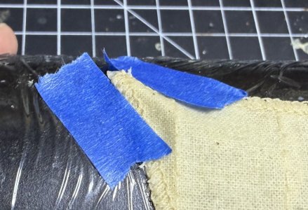
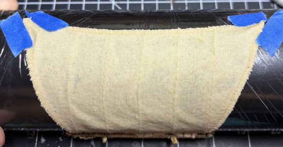
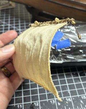
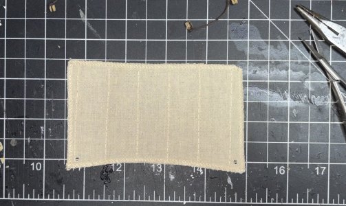
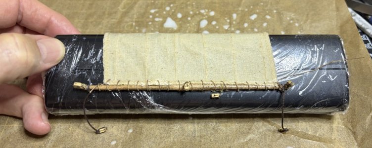
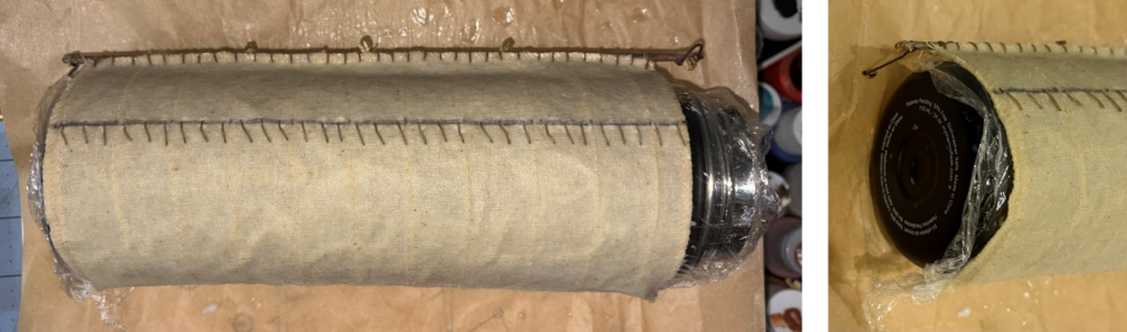
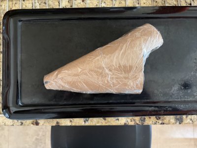
I searched and found the travel case for my electric toothbrush. It was not an oval, but it gave me the shape I needed.

I wrapped the case in saran wrap and completely wet the sail with the 50/50 glue and water mix. I then positioned the sail on the case in such a way that it created the billow I was looking for.
IMG_1302.jpeg
And waited as it takes about 24 hours to completely dry.
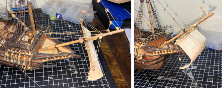
IMG_1303.jpeg
While it was drying, I jumped over to the fore lower sail.

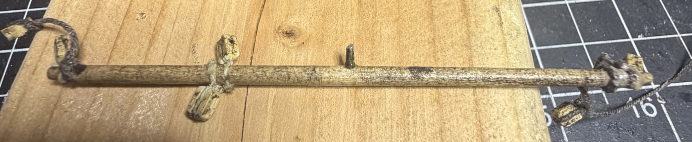
I drilled a hole in the yard for the pin.

I lashed the sail to the yard with Olha Batchvarov’s historical half-hitch spiral loops.
Picture2.png
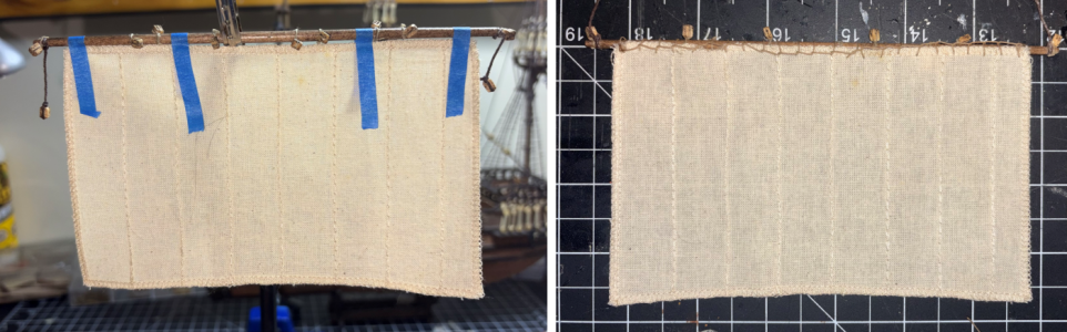
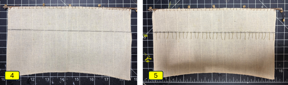
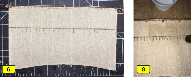
And then I did something new… reef band and reef points. There are several methods to make these, but I am going with a simple one; draw the band and then glue and snip. There is only one line of reef points on a 17th century Spanish galleon. To create the reef band, I measure down 1/3rd of the height of the sail (122mm) and draw a light line with a pencil on both sides of the sail.
IMG_1306.jpeg
The reef points are made with the same 0.1mm tan thread I have been using to lash the sail to the yards. They should be between 6mm and 9mm in length and spaced 6mm apart from each other.
IMG_1307.jpeg
After about 30 minutes, I trim the reef points at about 7mm, leaving a very nice-looking row of 25 of them. For some reason, I didn't take a picture... Once fully dry, I repeat the process on the other side of the sail.

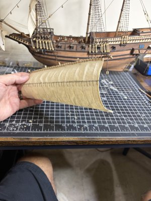
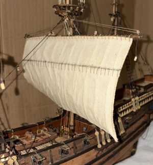
I soak the back side of the sail with 50/50 mix and then using my paintbrush, I pull the reef points slightly to the port side which when the yard is hung would indicate wind coming from the starboard side - simulating my starboard brace.

The sail goes onto the circular container with the frontside facing up. I give it a coat of the 50/50 mixture and again use the brush to pull the reef points slightly towards the port.

I use my fingers to hold the sail corners in place and push/pull the middle of the sail to the left. I then pinch the lower corners and set it aside to dry for 24 hours.
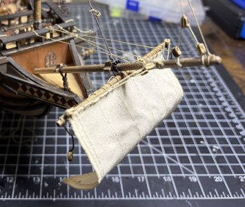
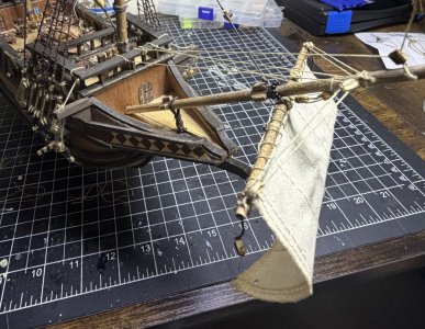
Back to the spritsail…

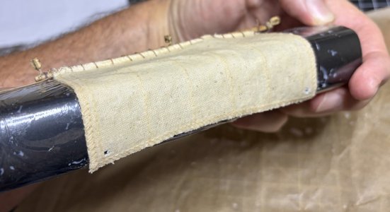
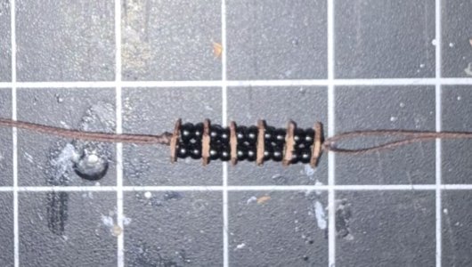
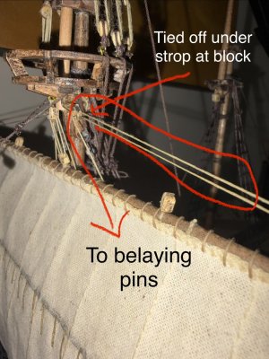
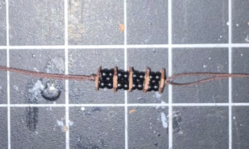
To create the parrel, I use some small black beads that I was able to find locally. To create the horseshoe over the top of the spritsail, I tie some knots and hold 9 beads in place.

I slide one end of the parrel between the sheet and the yard, then the other end goes up and over the bowsprit. I align the pin in the yard to the hole in the bowsprit, and while holding them together, I slide the other end of the parrel between the yard and the sheet. The two ends wrap around the yard and are fed back up and over the bowsprit where I lock it in place with a square knot.
Picture3.png
I now go back to the instructions and reeve and belay the spritsail halyard and two spritsail braces. They all get tied off to the rail on the front of the forecastle deck.

I use the two spritsail braces to assist with the starboard brace that I molded the sail for.
Picture4.png
While belaying these lines, I noticed that I belayed the fore topmast stay - tackle to the wrong place on the forecastle railing. I’ll be able to work around it.
IMG_1315.jpeg
IMG_1316.jpeg

I will now switch to the lower yard on the foremast.

Time for this portion: 10 hours
Total time to date: 366 hours
 

Attachments

Lower Mast Rigging & Block Audits
Session Start: August 28, 2026
Session End: September 5, 2026
Session Time: 13 Hours
Total Build Time: 379 Hours

In addition to posting a less wordy and condensed build log, I am trying something new with this one… I’m working with Gemini (Google’s AI chatbot) to write the 1st draft of my posted build log, which I’ll edit, correct, and add to as needed before posting.

I’m doing this for a couple of reasons:
  • Writing a log is time consuming, and while I enjoy writing, I only have so many free hours. I also write, edit, and distribute the monthly newsletter for the Rocky Mountain Shipwrights. That’s a big lift, so I need to cut back somewhere.
  • Recently I started working with Gemini when I was having questions about my build, which I was having more and more as I got further and further into my first sails. Felling comfortable with the tool, I thought I’d give this a try. If I don’t like it, I’ll switch back.
I would really like to get some feedback on my using AI plus who else has added it as a tool to their workbench.

This block of 13 hours marked the completion of the lower yards on both the foremast and the mainmast for El Molino. It turned out to be a period of troubleshooting, material optimization, and auditing old rigging choices I made months ago.

Here is the condensed breakdown:

The Foremast Lower Yard & Custom Parrels

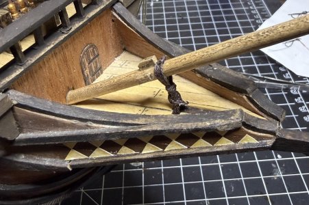
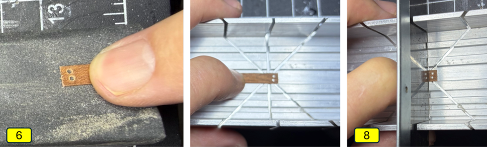
This yard introduced me to my first double-row parrel ladder—a system using alternating rows of vertical wooden ribs and rolling trucks. The ribs were built using leftover walnut veneer planking and the trucks were made using locally sourced beads.

The Veneer Shield: To stop my 0.2mm x 5mm planking veneer from splitting, I coated both sides in white glue and let it dry before drilling two 0.7mm holes. I then ran a needle file through the interiors to smooth out any thread-snagging burrs.

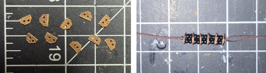
The Parrel Setup: I cut the veneer into 3.5mm x 5.0mm micro-ribs, chamfered the corners at 45 degrees, and strung them into a tight R-BB-R-BB-R-BB-R-BB-R-BB-R sequence using 6 ribs (R) and 10 nested beads (B).
IMG_1331.jpeg
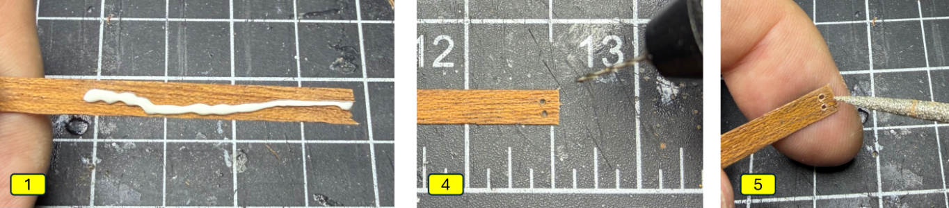
Making the ribs:
  1. Coat both sides of the 0.2mm x 5mm veneer with white glue and let it dry.
  2. This will strengthen the veneer and reduce splitting.
  3. Sand
  4. Drill two 0.7mm holes along the 5mm side.
  5. Lightly sand the holes with a thin pencil file.
    Picture1.png
  6. Sand the entire board.
  7. Lightly sand the holes again with a thin pencil file.
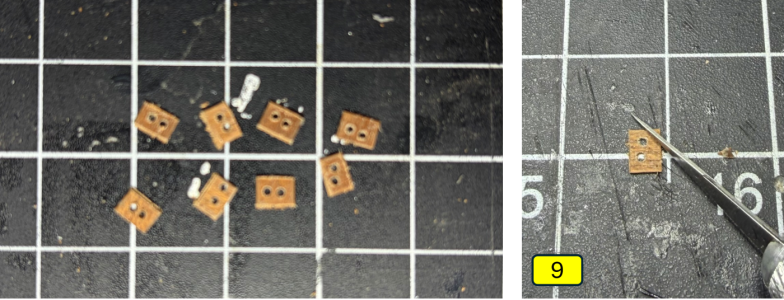
  8. Cut the veneer in a hobby miter box saw making each piece about 3.5mm x 5mm.
    Picture2.png
  9. Cut two of the corners off using a hobby knife.
    Picture3.png
  10. Sand.
Picture4.png
The Mount: The yard pin was seated, lines pulled taut, and the parrel threads were routed back over the yard to tie off with a square knot and a drop of CA behind the mast. The halyard was roved down to the fife rail post.

Proactive Rigging Discoveries
I realized that trying to feed a needle threader between a mounted block and its tight rope strop after the yard is mounted is incredibly frustrating. The blocks to this point had been installed at various points in my build, probably going back to October 2025.
IMG_1386.jpeg
The "El Molino" Fix: I established a new workflow: For existing blocks that have already been installed/mounted, instead of waiting until the yard has been mounted (and in the way), I will now add the running rigging line before the yard is attached. This little step makes it a lot easier to thread the needle threader between the block and its strop.
To test the theory, I pre-strung the foremast topsail lines under the cross trees while the space was wide open. It was infinitely easier.
IMG_1387.jpeg
Future Upgrade: On all future builds, I will be moving entirely to figure-8 strops for blocks instead of tying simple loops around the block. It looks cleaner and allows the blocks to rotate freely when routing lines. When building the figure-8 strops, I will also add the rigging line between the block and the strop. After I finished this section, I found out that the connection point of the rigging line to the block is at a “becket,” or at least I believe that is what it is called. Ralph B from the Rocky Mountain Shipwrights showed me a pretty slick way of using a figure eight strop along with a bead to simulate the becket. It is probably too late for El Molino, but I’ll including them in future builds as well.
Picture6.png
The Main Lower Yard

As the biggest sail on the ship, this was prepped flat on the bench: laced with Olga Batchvarov’s half-hitch loops, marked with a single 2B pencil reef band, and 7mm long reef points at a 6mm spacing. These were anchored to the front and back of the sail with white glue.

The Circular Mold: The sail was drenched with a 50/50 PVA/water mix that was “painted” on. The reef points were pulled to the port and the sail was swept to port on my circular container. The container was barely big enough for this main sheet - a good reminder that I will need larger forms if/when I work on larger models!

Making the Billow:
  1. Drill a 0.6mm hole in the yard for the pin.
  2. Temporarily attached the sheet to the yard.
  3. Lashed the sail to the yard with Olha Batchvarov’s historical half-hitch spiral loops.
  4. Used a pencil to draw in the reef band (again only one).
  5. Using white glue, glue lines of at least 7mm at 6mm spacing along the reef band.
    Picture7.png
  6. Once the glue has dried, trim the lines at 7mm, creating the reef points.
  7. Cover the back side of the sail with a 50/50 white glue and water mixture.
  8. Pull the reef points so they are angled towards the port side with a paintbrush.
    Picture8.png
  9. Position the sheet front face up on the covered circular container.
  10. Cover the front side with the 50/50 mixture.
  11. Pull the reef points so they are angled towards the port side.
  12. Hold the sheet square to the container using your thumbs and middle fingers but push/pull the center towards the port side using your index fingers.
  13. Pinch the lower corners of the sheet.
    Picture9.png
  14. Let dry for 24 hours.
IMG_1357.jpeg
After a 24-hour cure, the yard was pinned into its 20-degree Starboard Brace hole, clamped with its 2-row parrel, and the halyard was belayed down to the fife rail.
IMG_1370.jpeg
The Great Double-Block Audit (The "Argh!" Moments)

While preparing the main braces, I realized I had accidentally installed double blocks at the yard arms instead of singles. Looking over at the foremast to compare... I found I had done it there too! Argh!
IMG_1371.jpeg
The Correction: I pulled all four off and swapped them out for single blocks wrapped in clean figure-8 strops. This had a great secondary benefit: it recovered 4 much-needed double blocks for my spare parts inventory (solving why I had run out of them earlier!).
IMG_1372.jpeg
This required me to un-belay the foremast lower braces, but it was a choice I can live with.

The Second Discovery: While re-reeving the main braces, I found another set of mistaken double blocks sitting underneath the circular top on the mast. I had done all of these wrong block back in November! At this point I made the decision to grab a beer and head to the pool. The next day I swapped them out the while waiting for my Spanish class to start.

Current Status: All block corrections are complete. The halyards and all braces are successfully roved and tied off to the fife rail pins.
IMG_1369.jpeg

IMG_1373.jpeg
Another re-christening

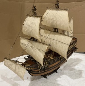
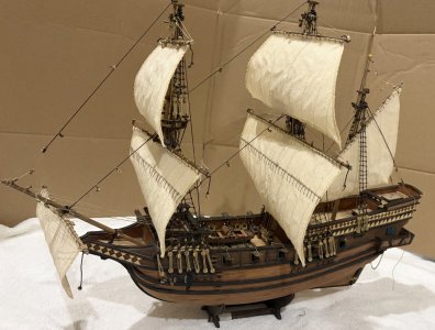
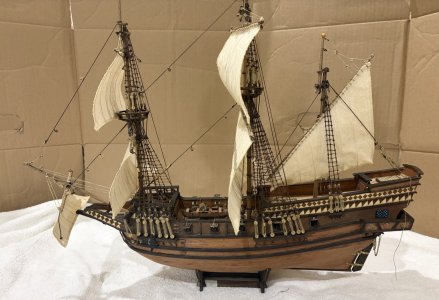
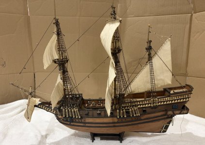
The ship is the OcCre’s Buccaneer, which I re-christened the Molino ages ago. The kit is not based on a specific ship, but rather a generic pirate ship. Given it is not a real ship, I feel free to make any changes I desire to the ship (unlike my other model the Bluenose which I will only make changes if they are true to the actual ship).

The latest change comes courtesy of Gemini. During one of my discussions with Gemini, the ship, which is a 17th century Spanish galleon, was called by Gemini “El Molino.” I liked the Spanish feeling and the name change stuck.

Next Up: The Mizzen Lateen Sail
 
MIZZENMAST LATEEN RIGGING

Session Start
: September 6, 2026
Session End: September 9, 2026
Session Time: 5.5 Hours
Total Build Time: 384.5 Hours

I am going for round two with Gemini (Google’s AI chatbot) to write the 1st draft of my build log, which I will edit, correct, and add/subtract as needed before posting. It was nice not writing out my full notes (and stories) while working on the ship. Instead, I tracked my progress in bullet points which I then fed in Gemini.

Lacing & Shape:
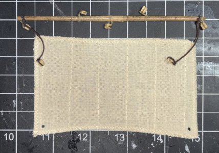
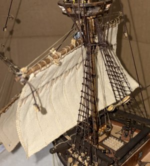
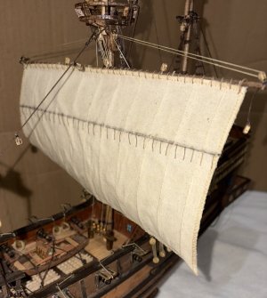
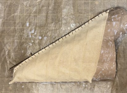
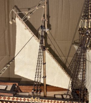
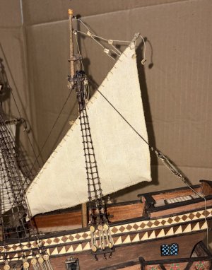
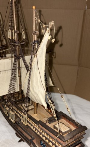
The premade sail was anchored from peak to tack along the angled yard using Olha Batchvarov’s uniform spiral lacing at 6mm spacing. The sail was then drenched using a brush-applied 50/50 water-and-PVA glue mix and left to cure over a custom plastic-wrapped conical mold (made with toilet paper holders and scotch tape. To match the ship's established starboard brace, the center of the lateen sail was swept toward the port side, and the lower corners were pinched to mimic wind tension.
IMG_1375.jpeg

IMG_1388.jpeg

Parrel Production:

I made hopefully all the vertical ribs for the lateen sail as well as the remaining two topsails. I continued utilizing 0.2mm x 5mm veneer pre-treated with white glue to prevent splitting. Drilled with 0.7mm dual holes, sanded with a micro pencil file, and miter-cut to 3.5mm. A heavy-duty, double-row parrel necklace was assembled using the pattern: R-BB-R-BB-R-BB-R-BB-R-BB-R (6 ribs, 10 double beads).

Stepping the Yard:
Following historical geometry, the rigid yard assembly was mounted to the mizzen mast, sitting perfectly behind the mainmast shrouds and ratlines. The yard was locked to the mast at a 70-degree offset utilizing a mounting pin and the completed bead parrel.

Running Rigging:
After the tension of the halyard pulled the fife rail off the bulwark, I was forced into a waiting period as it was re-glued. Once it was cured, the mizzenmast halyard was pulled taut and belayed successfully to the port-side fife rail on the quarterdeck.

The Lift Tackle:
I removed the previously installed single block from near the top of the mast and replaced it with an upgraded figure-eight stropped block. The lift line was anchored below the mast truck, and instead of a simple knot, I double seized it. Instead of a tan thread, I used black thread for the seizes for contrast. The line was roved through the yard's pyramid blocks and belayed to the starboard-side fife rail.
IMG_1394.jpeg

IMG_1396.jpeg

IMG_1399.jpeg

IMG_1400.jpeg

IMG_1397.jpeg

IMG_1398.jpeg

Next Up:

The Two Topsails (and maybe a different AI chatbot)
 
In this session, I advanced El Molino’s upper rig by installing both topsails, replacing simplified crosstree blocks with more realistic custom assemblies, and completing the associated halyards and braces in an 11-hour session.
  • Session Start: September 9, 2026
  • Session End: September 13, 2026
  • Session Time: 11 Hours
  • Total Build Time: 395.5 Hours
One additional AI change. I did everything as I did previously, but the fed the build log into Copilot and looked at its recommendations.

Main Topsail Canvas Prep: Stitched the premade canvas to its yard using Olha Batchvarov’s half-hitch spiral loops at 6mm spacing. The yard was pre-drilled for its mounting pin, and the back side of the canvas was drenched with a brush-applied 50/50 white glue and water mixture. The assembly was positioned front-face up on a covered circular container mold. The front face was then coated with the mixture. To match the port-side sweep of the wind, the center of the canvas was pushed and pulled toward the port side while the lower corners were pinched to mimic wind tension before curing for 24 hours.
IMG_1406.jpeg
Crosstree Block Modification:
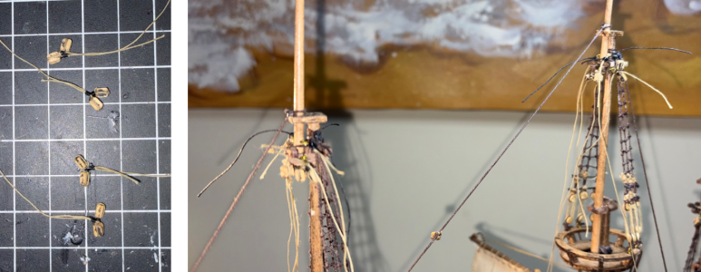
Rigging-diagram review showed that the kit’s crosstree double blocks were a beginner-friendly simplification: one sheave served the braces and the other the buntlines. To improve realism and keep the two systems visually distinct, I replaced all four double blocks with custom dual-single-block assemblies, a refinement that may be subtle to most builders but materially improves the rigging detail.

Single-Double Block Production: Eight individual single blocks were prepped by sanding, filing corner grooves, drilling out holes, and staining. Using 5-inch lengths of tan line, four custom figure-eight loop strops were created. Single blocks were nestled into the loops on each side. Four separate mounting loops were formed using tan line with contrasting black seizing. These seized loops were slid over the blocks and tightened securely around the central waist of the figure-eights. The assemblies were locked with CA glue and the tails were trimmed.
Picture1.png

Picture2.png

Picture3.png

Picture4.png
Stepping & Integrated Rigging:
The four completed double-single blocks were lashed securely to the eyebolts under the mast crosstrees where the kit had specified double blocks. These were then locked with CA glue. Moving away from a piece-by-piece assembly, the yards were attached in more of a simultaneous mounting sequence:
  • The first end of the parrel line was fed from the back of the sail under the yard to the front face.
  • The halyard blocks were roved using a needle threader, leaving plenty of extra slack line.
  • While tightening the halyard line, the parrel necklace was wrapped around the back of the mast, and the remaining end of the parrel was fed under the yard to the front face.
  • Both parrel ends were pulled over the top of the yard and fed back to the rear of the mast.
  • While tightening the halyard line even more, the yard mounting pin was aligned and seated directly into the mast timber.
  • The parrel lines were tensioned and secured with a square knot.
  • Final tension was pulled through the halyard block tackle.
Parrel Fabrication: The double-row parrel necklaces were scaled down to account for the narrower topmasts. Each necklace was configured with 4 sets of double beads (8 total) separated by 5 vertical ribs.
Picture5.png
RUNNING RIGGING & FALLS
The Halyards: I’m still struggling during block reeving, as I repeatedly had the line exiting on the incorrect side of the sheaves, necessitating multiple re-reeves. Once properly oriented, the halyard lines were routed cleanly down through an opening in the flooring of the circular tops and belayed to the quarterdeck fife rail.
IMG_1431.jpeg
The Braces:
The installation of the braces proved exceptionally straightforward, a direct benefit of upgrading to the custom double-single block configuration. The lines were roved through the new blocks and belayed cleanly to the quarterdeck railing. Rather than utilizing simple knots, the four brace lines were anchored to their eyebolts above the crosstrees and dressed up with black thread seizes, locked with CA glue.
IMG_1432.jpeg
Fore Topsail Execution:
Following the successful installation of the main topsail, the entire sequence was repeated on the fore topsail. The pre-billowed canvas was brought to the foremast, its custom 8-bead parrel was laced, and both the halyard and braces were fully roved, tensioned, and belayed. All excess rigging tails across both masts were cleanly trimmed.
IMG_1433.jpeg
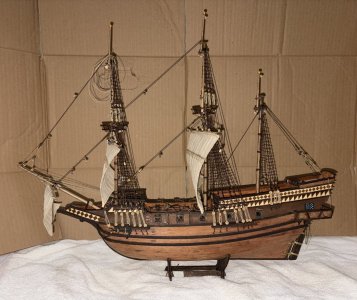
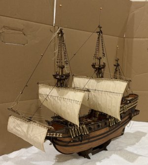
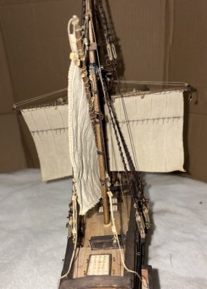
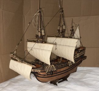
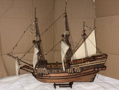
All upper sails are officially flying proud, fully balanced, and locked into the starboard-brace alignment.
IMG_1434.jpeg
Next up:
After a one-week break in Guadalajara and Ajijic, I’ll return to rig the topsail sheets to the lower yards, followed by the clewlines and buntlines across the upper canvas.
 
In this session, I advanced El Molino’s upper rig by installing both topsails, replacing simplified crosstree blocks with more realistic custom assemblies, and completing the associated halyards and braces in an 11-hour session.
  • Session Start: September 9, 2026
  • Session End: September 13, 2026
  • Session Time: 11 Hours
  • Total Build Time: 395.5 Hours
One additional AI change. I did everything as I did previously, but the fed the build log into Copilot and looked at its recommendations.

Main Topsail Canvas Prep: Stitched the premade canvas to its yard using Olha Batchvarov’s half-hitch spiral loops at 6mm spacing. The yard was pre-drilled for its mounting pin, and the back side of the canvas was drenched with a brush-applied 50/50 white glue and water mixture. The assembly was positioned front-face up on a covered circular container mold. The front face was then coated with the mixture. To match the port-side sweep of the wind, the center of the canvas was pushed and pulled toward the port side while the lower corners were pinched to mimic wind tension before curing for 24 hours.
View attachment 636194
Crosstree Block Modification:
Rigging-diagram review showed that the kit’s crosstree double blocks were a beginner-friendly simplification: one sheave served the braces and the other the buntlines. To improve realism and keep the two systems visually distinct, I replaced all four double blocks with custom dual-single-block assemblies, a refinement that may be subtle to most builders but materially improves the rigging detail.

Single-Double Block Production: Eight individual single blocks were prepped by sanding, filing corner grooves, drilling out holes, and staining. Using 5-inch lengths of tan line, four custom figure-eight loop strops were created. Single blocks were nestled into the loops on each side. Four separate mounting loops were formed using tan line with contrasting black seizing. These seized loops were slid over the blocks and tightened securely around the central waist of the figure-eights. The assemblies were locked with CA glue and the tails were trimmed.
View attachment 636195

View attachment 636196

View attachment 636197

View attachment 636198
Stepping & Integrated Rigging:
The four completed double-single blocks were lashed securely to the eyebolts under the mast crosstrees where the kit had specified double blocks. These were then locked with CA glue. Moving away from a piece-by-piece assembly, the yards were attached in more of a simultaneous mounting sequence:
  • The first end of the parrel line was fed from the back of the sail under the yard to the front face.
  • The halyard blocks were roved using a needle threader, leaving plenty of extra slack line.
  • While tightening the halyard line, the parrel necklace was wrapped around the back of the mast, and the remaining end of the parrel was fed under the yard to the front face.
  • Both parrel ends were pulled over the top of the yard and fed back to the rear of the mast.
  • While tightening the halyard line even more, the yard mounting pin was aligned and seated directly into the mast timber.
  • The parrel lines were tensioned and secured with a square knot.
  • Final tension was pulled through the halyard block tackle.
Parrel Fabrication: The double-row parrel necklaces were scaled down to account for the narrower topmasts. Each necklace was configured with 4 sets of double beads (8 total) separated by 5 vertical ribs.
View attachment 636199
RUNNING RIGGING & FALLS
The Halyards: I’m still struggling during block reeving, as I repeatedly had the line exiting on the incorrect side of the sheaves, necessitating multiple re-reeves. Once properly oriented, the halyard lines were routed cleanly down through an opening in the flooring of the circular tops and belayed to the quarterdeck fife rail.
View attachment 636200
The Braces:
The installation of the braces proved exceptionally straightforward, a direct benefit of upgrading to the custom double-single block configuration. The lines were roved through the new blocks and belayed cleanly to the quarterdeck railing. Rather than utilizing simple knots, the four brace lines were anchored to their eyebolts above the crosstrees and dressed up with black thread seizes, locked with CA glue.
View attachment 636201
Fore Topsail Execution:
Following the successful installation of the main topsail, the entire sequence was repeated on the fore topsail. The pre-billowed canvas was brought to the foremast, its custom 8-bead parrel was laced, and both the halyard and braces were fully roved, tensioned, and belayed. All excess rigging tails across both masts were cleanly trimmed.
View attachment 636202
All upper sails are officially flying proud, fully balanced, and locked into the starboard-brace alignment.
View attachment 636203
Next up:
After a one-week break in Guadalajara and Ajijic, I’ll return to rig the topsail sheets to the lower yards, followed by the clewlines and buntlines across the upper canvas.
Nicely done Hugh! The sails look great! Magic Mike
 
EL MOLINO BUILD LOG 18 (with help from Gemini & Claude)
In this session, the shipyard went dark on physical timber work, shifting the watch entirely into figurine procurement and heraldry design, closing out the session with zero logged hours on the clock but roughly 10 hours of unlogged research.

Session Start: September 14, 2026
Session End: September 20, 2026
Session Time: 0 Hours (~10 Hours Research, Unlogged)
Total Build Time: 395.5 Hours

Leaving the heat and humidity of Puerto Vallarta behind, we took a short trip inland first to Guadalajara for a visit with a friend, then on to Ajijic to reunite with former neighbors.

Even though I was physically separated from the workshop, I used the time for some aesthetic planning, historical lofting, and procurement.

Recruiting the complement
A few things had been brewing in my subconscious for a while as I was having serious doubts about hoisting a Jolly Roger above El Molino based upon Kenny Chensey’s “No Shoes Nation” tour (a skull & crossbones where there is a cowboy hat on the skull) and whether I should have figurines on board.

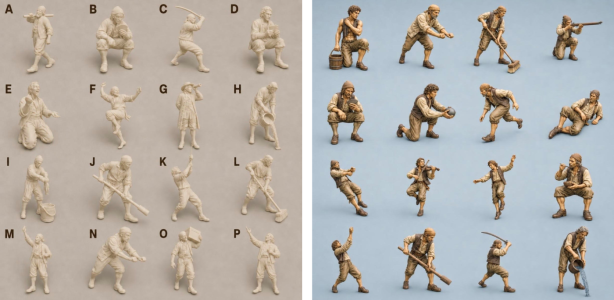
Starting with the crew, after consultations with Gemini regarding historical crew complements at 1:100 scale, I decided on a muster of approximately 15 figurines, balancing command officers on the quarterdeck against working hands deployed in tactical clusters across the waist and forecastle - enough for a sense of action without cluttering the deck lines. With the decision made, it now was up to where do I get them and how do I get them to Mexico.

Crew Procurement
I found a great set of resin "Model Ship Crew Miniatures" on Etsy from Miniature Heavens. They were not too expensive, and were even less if I sourced them from the Mexican catalog of Etsy and shipping them to my condo. The total for the crew was around $50US (including delivery) while the same figures in the states and shipped to the states was about $70US. Delivery is expected within a few weeks.
Combo3.png
Painting Party

Once the crew arrives, they'll need full painting, which resurrects a childhood skill set. During my teenage years I hand-painted a massive array of lead D&D miniatures - treasures that were ultimately liquidated during our downsizing and moving to Vallarta. Back then, a simple wooden toothpick served as my primary painting tool. It'll be a good test of whether those youthful hands and micro-painting skills still hold up at the bench. A full inspection and review of the crew will be logged upon arrival.

Designing the Colors
Bringing a lifelike crew aboard both exposed and helped me decide the conundrum of the No Shoes Nation flag. My plan for a while now has been to fly a playful, Jolly Roger, complete with a cowboy hat on the skull, but it no longer fits the fidelity El Molino had grown into. El Molino needed her own authentic, localized colors.
Combo2.png
To loft the personalized heraldry, a digital collaboration was opened with Claude AI. Navigating the process taught me a useful workflow lesson when working with AI (and not just working with Claude, but many AI systems):
  1. Questions/conversations resulting in graphics (a flag) burn through data quotas quickly.
  2. Keeping conversational threads small and hyper-focused prevents the system from bogging down.
  3. The underlying memory framework preserves critical context across sessions, so launching fresh, clean chats keeps computing speeds sharp and avoids premature quota exhaustion.
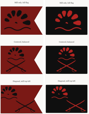
The digital drafting spanned four distinct sessions under Claude’s free-tier restrictions to arrive at a series of clean, geometric concepts. To match the architectural lines of our building, the final design settled on a few possible designs. All leaned on crisp lines and negative space based around a minimalist silhouette of a traditional water mill wheel (our Condo’s “logo”.) Other designs also included a set of crossed cutlasses.

Flag Specs & Geometry
With the general conception of the flag locked in, several physical properties remain open for experimentation ahead of the printing phase:

Dimensions
Scaled for 1:100, the flag should be 0.40" x 0.65" for a standard rectangle, or a slightly elongated 0.45" x 0.80" should a swallowtail cut be chosen.

Chromatic Contrast
The color palette is still under evaluation. A black emblem on a "No Quarter" blood-red field is historically terrifying, but reversing the palette to a blood-red emblem over a midnight-black field may offer sharper visual pop at this scale.
Combo1.png
Fabrication Method
I am still deciding how to create the flag, though printing the mirrored graphic onto ultra-thin cigarette paper taped to a standard carrier sheet remains the primary strategy.

This entire section was dedicated to pure research, asset tracking, and structural prep, no hours were added to the total build time, so it remains exactly where the previous session concluded.

The ship's papers are updated, the crew is chartered, and the customized flag geometry is saved in the locker.

Next up: Session 19, rigging the foremast braces.
 
Back
Top