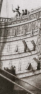
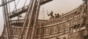
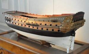
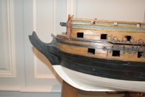
SAINT PHILIPPE 1693 in 1/64 PoB by Iterum

worried_cat_2-1.png

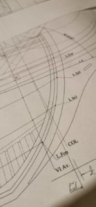
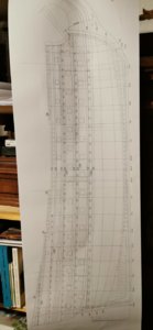
I will start tomorrow to check this by a coupled pair of frostpaper with the CL several times drawn parallel on it and the distances were taken from the exact former positions from PLATE1 1.

I am going to lay this over all the decks plans drawings to check the position of the formers and if there is a diffrence I mark it by a colour pencil to point it out clearly. In what plate what difference accounted.

My masterlines are always Centerline on the middle of the keel and the MGM;
My starting point is the crossing CL/MGM.
Has anybody in here any other/easier/better/simpler/cleverer suggestions?
 
Heinrich I don't know.I am very wary of any drawings that are possibly derived from CAD.I have many experiences in my day job with so called "true Views" which are not that.Typically the CAD operator had clicked on two points for a datum for the projection but sometimes these are wrong.I had many a heated debate with the CAD operator that his drawing was wrong and an explanation from myself looking and pointing at the 3D model on the screen sorted the issue and a new view was produced.
Unfortunately this is not a possibility with these monographs,we can only try to relate to what information is shown.

Kind Regards

Nigel

Yes but it is a brutal step backwards* for the REPUTATION of Ancre Publishing. So I am in full doubt to any new plan of this house. Jean Boudriot "will turn around in his grave" we do say in Germany...

So I will have to do what, Nigel?

Stay at the two correct projections

A.) Formers plan
B.) Side view (Plate 1)

...and
C.) my building board is using the L.F.-distances from the Plate 1 the formers are rectangular and the keel in angled?

______
*compared to the beloved hand drawn plans of the 8pdf-fregat RENOMMEÉ (1744) for example.
 
Last edited:
If I were to build this model plank on bulkhead,I would build the rightway up with the keel sloping.This would be far easier to square the bulkheads up.I would work to the cross section of the waterlines plan which,from memory gives you a bulkhead every five frames.The bulkheads will work out around 50mm apart which will give you decent support for your planking.Have you calculated whether the cross sections are to the inside or outside of the planking?

Kind Regards

Nigel

Yes, Nigel, I do plan to build her upside down - having the L.F. parallel to the building board. So I will screw the boards on one level- this is the reason why I run the L.F. line through the complete bulkhead to cross the L.F.line of the CL on plate 1. :D
Hopefully I am as clever in reality as it looks to be in my mind...
 
Heinrich by Cross section,I mean the one shown in post number 8.You say you are also building upside down,in that case are you extending the bulkheads to a consistent height above LF?In 1/36 this worked out in excess of 100mm due to the sweeping sheer at the stern.I am going to use a board with two heights,i.e. a step raised 100mm for the front 2 thirds of the hull to reduce the height of the extensions

Kind Regards

Nigel
 
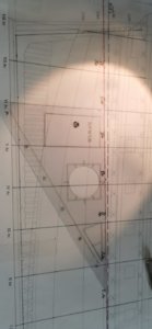
Okay I made the problem shifting by implementing a new layer rectangular to the formers crossing the L.F. at MGM.
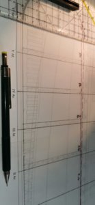
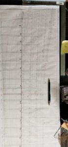
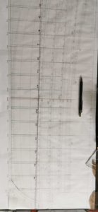
By this I get a layer parallel to the building board - to make it more obvious I colored it in the well known WWI "German Purple".

Additivly I brought in the grooves drawings for the formers at alltje Av. and Ar. lines:
IMG-20200229-WA0041.jpeg
IMG-20200229-WA0043.jpeg
IMG-20200229-WA0044.jpeg

Prooving rectangularity:
IMG-20200229-WA0037.jpeg
 
Hi Chris!! Glad to see you, here! So, you will build your Heller modification and this bulkhead SP simultaneously?

I will gladly follow along as the process of converting frame-up plans to a bulkhead construction is quite interesting in itself.

Hy Marc, great to see you in here - model building is quite a small galaxy ;)

And yes I decided to follow your idea to stay with the given Heller hull - "making a SAINT Phillipe from this kit may be the best you could do to it!" says a German modelshipbuilder to me about this project.

So the scratchbuild will first be a mock up of the hull to get a feeling for the shape. And for the detailing as she will be build as an unarmed hull model. This will keep away the deeper staircases, the ornamentation of the gun port lid's insides (without those under the transom).
When this is successful I will restart the build of three decker with fully detailed gundecks and a complete rigg - my wife told me she would sew the sails... :D the 1/92 kit bashing will help to get the shape of some details in a smaller scale.

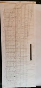
In the plan set there is a bit hidden a former plan on Plate 3 - as it shows the rabbet empty it is an unplanked plan.

Here my partly mirrowed solution in a Av. and Ar.-part:

IMG-20200226-WA0004.jpeg
And this would be very nice and smooth to build if there weren't these massive problems about the listed layers in the plan.

So let us look forward what is going on!
 
Heinrich by Cross section,I mean the one shown in post number 8.You say you are also building upside down,in that case are you extending the bulkheads to a consistent height above LF?In 1/36 this worked out in excess of 100mm due to the sweeping sheer at the stern.I am going to use a board with two heights,i.e. a step raised 100mm for the front 2 thirds of the hull to reduce the height of the extensions

Kind Regards

Nigel

By laying the German Purpel Layer rectangular to the bulkheads I have go a parallel line to the building board. Hopefully this will help a lot...
 
Memo note to myself:

As I think it is boring to build the same ship :D twice I decided to use the hull for the mock up as TONNANT there is a picture on page 9 in the Monography showing her possibly:

Polish_20200301_105917218.jpg
Here beside my admirals hobby book (she will be the sail maker) .

The transom is quite similar in construction:
IMG-20200301-WA0007.jpeg

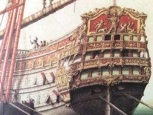
The coloring is very interesting as only the space between the wales one seems to the darker:
Polish_20200301_111052061.jpg

The decor is at the Upper DECK (UD) without lattice and I would think the Medium Deck (MD) had some arm and flag fasci like decoration. My idea to colour is about a greenish grey and warm gold: (to keep her distinguished from the red Flagship).

Polish_20200301_110813082.jpg

Here the colour I am longing for (found on a door at Chateau de Versailles:

65833a0749be4b071fb3ee16df112aa8--chateau-versailles-chateaus.jpg

What do you think about this?
 
Last edited:
BTW:

Yesterday G. Delacroix wrote to this massive plans quality critism by me at MSW: "It is certain that certain new plans of Ancre present anomalies which it is difficult for me to justify." That sounds like good news - in the team a brilliant plan drawing specialist takes care for the reputation of the Ancre publishing. Hopefully this will be discussed inside.
 
Tonnerant is an equally nice vessel and yes I get the point about not building the same ship twice.

It is interesting that GD recognises there "may be issues" with the plans.I knew it would not be plain sailing (excuse the pun) when I bought the Monograph,other renowned builders had commented on the Francois Monograph by JCL that there were many errors.

Kind Regards

Nigel
 
...and I did find a TONNANT - the ship from 1740 and found the right green-grey I am longing for:
LeTonnant1740a.jpg.69db15455bc5f838c959eb96bc1a46af.jpg

BUT as you cannot get it all;
no figure head is looking ahead:

LeTonnant1740.jpg.c2415ebbcffd0b27a210cdc278c81ae8.jpg


II. Back to the plans - and the roots:

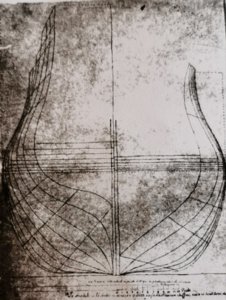
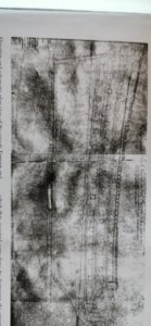
Here the original plans Mr. Lamineur used:
Polish_20200301_160635613.thumb.jpg.3e6476e945021021451b139ba5cf8382.jpg
The body plan with an horizontal keelson

IMG-20200301-WA0034.thumb.jpeg.1c6d969c7f05eba7f1ec982bff609030.jpeg

the sideview

Polish_20200301_160924530.thumb.jpg.39bfd5b71acd5558f3df3343005b0341.jpg
And here the decks line
 
Hello friends of the baroque trezett of the SAINT PHILIPPE 1693!

Here some music (for those who would like to know what I do listen to not to explode when working with this horrible planset) of the period we deal with:


I recently do work on the centerboard's design with the help of Pl.16 (under the frost-paper) to figure out where to place the upper deck and those above. These are the ones that you can see as the gunport are closed.

IMG-20200302-WA0012.jpeg
So my question is:

What distance is right between top of the bulkhead and top of the deck's planking?

I think about using 4mm poplar-plywood (I have a big stock of). adding 0,7mm maple vaneer on top for the imitation of the decks panking so I think about 5mm distance.

This 3/10mm are an issue?

Or mustn't I be too tolerant and do I have to work with 4,7mm?


Thanks for your patience help and interest!
 
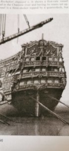
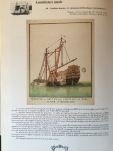
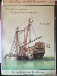
Hi:I have a picture about the
“sheer hulk for the kings vessels at Rochefort shipyard”.


View attachment 136035

Thank you very very much, Iflxy, for this highly interesting picture - this clearly votes for a red basis not a grey green as I thought. :oops:

Have you got any idea from wath time colouration dates and could you kindly tell the book to me so I can buy this, too (as book 25.001)???
 
Thank you very very much, Iflxy, for this highly interesting picture - this clearly votes for a red basis not a grey green as I thought. :oops:

Have you got any idea from wath time colouration dates and could you kindly tell the book to me so I can buy this, too (as book 25.001)???
Hi Iterum
I bought this book from abebook. Regarding color, I think you can ask G. Delacroix, he is an expert.
Kind Regards

Li
 
Back
Top