SAINT PHILIPPE 1693 in 1/64 PoB by Iterum

Hi,

From my view as a beginner !!!

With formers do you mean the frames i think. The section plan that you show is 90 degree to the keel. It´s right in my opinion.
But this plan has nothing to do with the frames !!! The section plan defines "only" the hull of the ship. You have to check in the sheer drawing
if the lines with the romulan numbers have 90 degrees to the keel ! The big side drawing, should be drawing no. 1....
The frames are not shown in the section plan, this is a other step.

1584175935229.png
 
Last edited:
Hi,

From my view as a beginner !!!

With formers do you mean the frames i think. The section plan that you show is 90 degree to the keel. It´s right in my opinion.
But this plan has nothing to do with the frames !!! The section plan defines "only" the hull of the ship. You have to check in the sheer drawing
if the lines with the romulan numbers have 90 degrees to the keel ! The big side drawing, should be drawing no. 1....
The frames are not shown in the section plan, this is a other step.

View attachment 137864
Sorry Oliver, thanks a lot for your enthusiasm!

:( but also this plate N°1 is drawn wrongly in my opinion due to the horror the keel is not rectangular with frames - it does look quite well on a distance:
IMG-20200314-WA0061.jpeg

...but do not proof it in detail:
IMG-20200314-WA0062.jpeg

It is again this well-hated 0,9° deviation:
IMG-20200314-WA0065.jpeg

I am really sorr yabout this result - for some moments you have had produced some sort of cliffhanger to me!
 
Last edited:
okay let us leavethe Vale Of Tears for some moments with view on the books my postman brought to me :
Polish_20200314_151504164.jpg

Leaving through the DU BOIS DONT...
I recognized the model of a 82gun ship contemporary to SP on page 70
with an UpperDeck without gunport lids, too.
Polish_20200314_152157476.jpg
Polish_20200314_152739114.jpg
But with a hight of the UD as tall as the two decks below - standing appart from SP also...

So there is still unfinished business
 
Hm.....strange..... i would bet money that it fits, but....hm

Can you measure the distances between the sections and compare with the distances from the sections in the waterlineplan ?

View attachment 137897

Yes Oliver by this my grand uncle lost a hole chateau in Saxonia - by betting.

RECTANGULAR TO CWL:
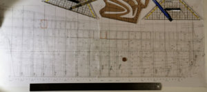
As construction is allways to prefer before measurement I cut the Plate N° 2 in half alongside the CL and placed it along the L.F.(blue) - the orange line is the main frame (M.G.M.).
by this we can easily compare the two plans' frames side-by-side:
Polish_20200314_154357108.jpg

The Ar.-section:
Polish_20200314_154259403.jpg

...and the Av.-section:
Polish_20200314_154326338.jpg

RECTANGULAR ALONG THE KEEL:
repeated this test alongside the keel and failed also:
Polish_20200314_155111012.jpg

The Av-section does not fit:
Polish_20200314_155139243.jpg

the Ar-part is a bit better but also failed at M.G.Ar. and followers towards the stern absolutely :
Polish_20200314_155546922.jpg

Disgusting result to see... I do get more and more annoyed by this plan set the more I do compare the basic line plans to each other.
And I really tried with a suitcase full of best will to try out anything.

I placed the WLplan in several angels all over the sideview but in no position ALL the frames does meet each other!

Also by using a pair of compasses only some frames do fit and nearly fit to each other. COL is the most irritating line at all!

First I thought the frames may have erraticly been lifted with the decks by some mismatching in the CAD process - but than the lowest frames arround M.G.M. should have been fine too - but they are not. The errors looks randomly. Perchance Nigel has some idea what may have happend - I think there is a pile of interacting errors that were partly repaired and partly still infecting the plans set. and this is the basic of the plan nothing sophisticated - it is the basics of the bottom of the ground you do build your olan onto. And this plan's grit doesn't fit into each other nothing can be right at all.

Here a drawing from Mattew Barker:
Polish_20200314_161619775.jpg
shiwing the principle of the construction and a modern drawing to the concept of frames, waterlines and the very rest:
Spanten_und_Wasserlinienriss-2.jpg

And also for sailings ships the basic rules are the very same:
image.jpg

also for some ships with a uneven keel (look on the CWL going diagonally through the drawing):
post-380-0-96909100-1388950610.jpg

What ¿©¥§>®™^>} ¥¿ is going on here???
 
Last edited:
Very strange.
The view from the waterplan cant be typical. The sections are lines in the waterplane. I think that the Waterplanplan is skew, But normal (90degree) to the sections.

If you rotate the Waterlineplan, the gap between the keel and the sectionplane, the sectionlines from both plans, need to hit each other.
Every sectionplanes has a fall to the bow. You need to rotate the plan to the right direction (red arrows).

1584200761101.png
 
Last edited:
Very strange.
(...)

If you rotate the Waterlineplan, the gap between the keel and the sectionplane, the sectionlines from both plans, need to hit each other.
Every sectionplanes has a fall to the bow. You need to rotate the plan to the right direction (red arrows).

View attachment 137915

I also tried this desperate method and certainly found some matches...

hands.gif

...but never all the frames matching their adequate WL relatives...
 
Oliver,no,nothing on the orientation of the view,you have to work it out yourself.Looking at the positions,no matter how you rotate the waterline plan,the lines will not match.They are not in proportional with one another.
As an example,one would have thought the sectional plans of the decks would be parallel to the waterline,err no,they are parallel to the keel.From a modelling perspective,this is a major pain.No matter which way up you would build a POF model,you would build the frames vertical and the keel sloping.This makes for intesting work inside the hull.Any measurements you take off these drawing are not true to the buildboard!

Kind Regards

Nigel
 
For a nightmare, I think I had given up at this stage, but these are probably expensive plans, so don't give up.
I hope you find this out, I wish you the best of luck.
.
 
Oliver,no,nothing on the orientation of the view,you have to work it out yourself.Looking at the positions,no matter how you rotate the waterline plan,the lines will not match.They are not in proportional with one another.
As an example,one would have thought the sectional plans of the decks would be parallel to the waterline,err no,they are parallel to the keel.From a modelling perspective,this is a major pain.No matter which way up you would build a POF model,you would build the frames vertical and the keel sloping.This makes for intesting work inside the hull.Any measurements you take off these drawing are not true to the buildboard!

Kind Regards

Nigel

Oh Nigel my comrade in suffering SP-plans!

I decided to go the boatbuilders way of science:
"Take this as a rule!
My big thumb!"

So I will go on with the frames errected rectangular onto the keel of the ship and by the fact I do build an enclosed hull to TONNANT I can slip the bulkheads into the centerboard by no hasitating about innter decks - because there are non.

As you can look down into the two staircases (memo to myself: N°17)

IMG-20200314-WA0134.jpeg
Done first...aaaaand....
IMG-20200314-WA0135.jpeg
Done second!

take the positions from plate and through the gritts I have to build some deep mocca brown boxes under the Upper Deck.

This will bring you to dome point of chaos when nothing will fit - and then there is the rural rule of the thumb to left the Valley Of Tears.
 
Norway, thanks for the pessimistic advice... these Plans are very expensive:
Screenshot_20200314_224330_com.android.chrome.jpg

This is the reason I bought them - after the good old idea:
"You get what you pay for -
what you don't pay you wouldn't get!"


Here my way of drawing my grooves in the centerboard:

IMG-20200314-WA0138.jpeg

Placing two dots on 6mm rectangular to the frame's line and through these I do connect the inner rabbet and the 100mm parallel dash-no dash line to the keel.

But as the Bulkheads are 6,4mm thick the will fit tight in this 6mm groove... IMG-20200314-WA0140.jpeg

An old charpentier's saying in Getmany is:
"You can cut off but never cut on the wood!"
 
The bad quality of many of the recent ANCRE plans is worrying. Perhaps, for that price and that questionable quality, you should just demand a refund. After all, in the age of CAD programs flaws which already would be bad in handdrawn plans are utterly inacceptable.
 
The bad quality of many of the recent ANCRE plans is worrying. Perhaps, for that price and that questionable quality, you should just demand a refund. After all, in the age of CAD programs flaws which already would be bad in handdrawn plans are utterly inacceptable.
Hello Redshirt. Mistakes are made by humans and not machines (computers). Unfortunately, they are unavoidable, yes, they can be minimized, The best course of action is most-likely contact ANCRE and report such discrepancies. I am sure they will note them and correct for the future releases, For the current, already printed publications, they can ad a 'rider' with corrected plans. ;)
 
At the moment I do work very silently on a side oroject...
my new © figure "Henri Benêt" (Henry the idiot)
Polish_20200318_235934087.jpg

She will be exactly two Royal French Feed long and will "help" on the shipyard... by showing the lengths and holding the coin for comparing issues...

That's all folks
 
At the moment I do work very silently on a side oroject...
my new © figure "Henri Benêt" (Henry the idiot)
View attachment 138840

She will be exactly two Royal French Feed long and will "help" on the shipyard... by showing the lengths and holding the coin for comparing issues...

That's all folks
Great idea - I am looking forward to be finally introduced to your new "friend" or better co-worker on the shipyard
 
Thanks guys!

but some really important questions:

What kind of wood you would tell me to buy as 1mm vanneer able to being bleeched by H2O2 to get a light hull surface? Imitating oak at 1/64?


But now to the centerboard standing inside on the keel. I am constructing this for days now - lets start at - better over the bow:
IMG-20200319-WA0026.jpeg

Here the end of the centerboard's top at the Breakhead bulkhead - how much distance do I have to keep in mind at this complex bent part?

The idea of construction of the breadhead bulkhead in this scetch here:
IMG-20200319-WA0036.jpeg
sidecut, topview, perspectivial drawing

I want to buld it from a thin plywood ("aircraft ply" called in Germany) and bending it into shape. Gluing the vaneer planks onto it.

15846357084424688090633410021025.jpg
At the pencil shows the upper deck - but how many millimeters I have to calculate for the deck planks (0,7mm vaneer of marple) wearing plywood and what thickness of plywood is a good choice?
Tan I can draw the top of the centerboard an the top of the bulkheads...

Here the open deck - where can I rise the centerboard under the upperst deck again?
IMG-20200319-WA0020.jpeg
There is a long empy area with no support fkr the deck at all:
IMG-20200319-WA0029.jpeg
The next Bulkhead will be at the beginning of the officers accommodation:
IMG-20200319-WA0031.jpeg

Do do I have to build here the first "real deck construction" by bars, knees and so on?

I am not shure if this is within my skills now.

But this deck is enclosed there were gunportlids!!! Luckily...
 
Last edited:
And I rediscovered* my figure head's drawing by E. Paris in lead pencil:
Polish_20200319_175514267.jpg
But is it reliable??? Does anybody know something about the TONNANT figureheads general theme at all???

*You shall know your literature to figure out where the important drawings were living IMG_18032020_224219_(921_x_1262_pixel).jpg
 
Back
Top