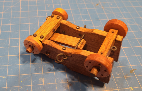
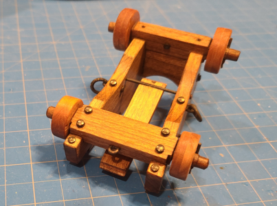
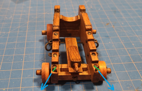
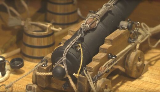
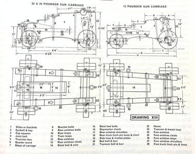
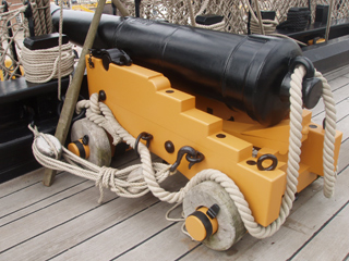
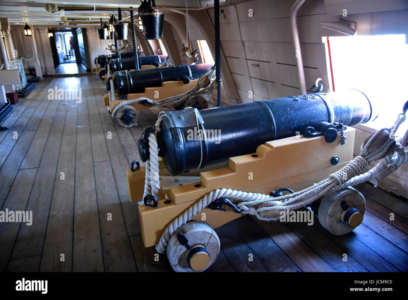
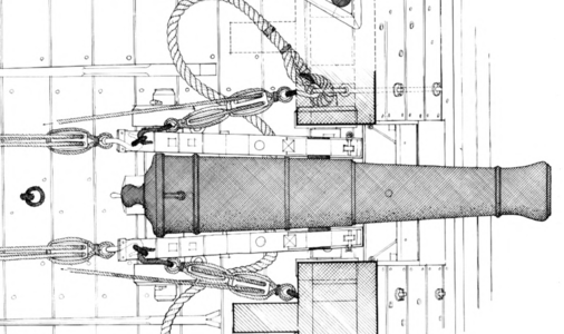
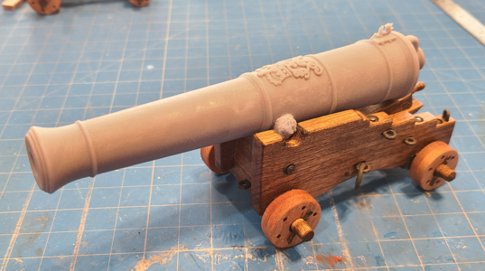
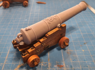
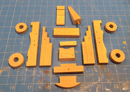
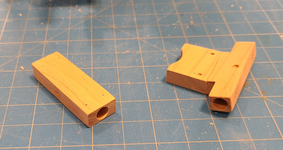
1:20 Scale Victory & Constitution Gun Models by Signet [COMPLETED BUILD]

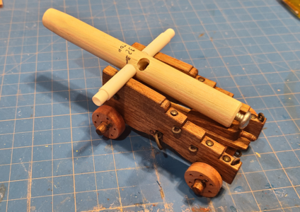
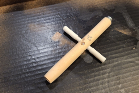
While I made the separate parts of the carriage fairly accurately, I knew from experience, and trial, that the brackets and other pieces could be easily skewed one way or the other, making the barrel not centered on the carriage. Since I don't have the barrels (and don't yet know if or when I can have something made), I made a substitute:
1668392952890.png
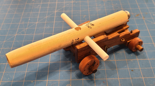
No, it doesn't look much like a cannon barrel. But it has a hole in the end, a screw "cascobel" to keep it rear-weighted and a removable trunnion of plastic tubing. One hole has been bored, at right angles to the cannon bore, for the 32-pound gun, and another for the 12-pound gun, each with approximately the same distance from the bottom of the barrel at the trunnion to the trunnion centerline. Thus, it will lay in place as the barrel will, and show any clearance problems with the bottom of the barrel and the transom. Oh, and the larger tubing that is removable over the smaller tubing represents the larger trunnion on the 32-pounder.

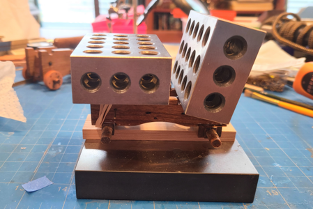
In an effort to glue the main four parts of the carriage (the two side brackets, the rear axletree and the front axletree/transom assembly) together squarely to the barrel, and spaced correctly, I used a number of rubber bands, shims on either side of the barrel and weights, atop a reference level piece of steel. You'll have to image what it looks like under this mess:
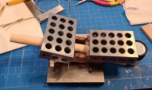
1668393367672.png

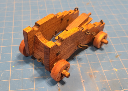
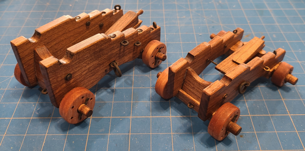
After gluing these main pieces together, it looked like this:
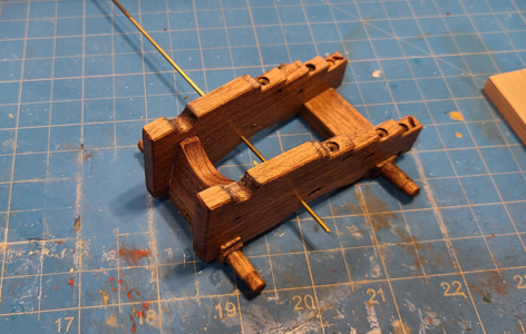
1668393882046.png
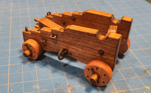
I had previously prepared the various rods, pins, loops, washers, etc. that connect and adorn the carriage. A mixture of copper, brass, coated brass (unfortunately), jewelry wire, brads and solder, I tired a new blackening agent: JAX Pewter Black. It states it works on pewter, lead, brass, bronze and copper (and on solder, which is mostly lead for my old stock). Despite an alcohol bath, vinegar etch, treatment and rinse, it did not cover all pieces well, and some at all. I went back to my staple product: Casey Brass Black, and it worked when JAX didn't. Overall, I wasn't very happy with the way the pieces were blackened: when buffed, it tends to come off, was blotchy in general, etc. But I'd put too much work into it to waste it, so I decided to assemble the carriage using the parts as-is. Areas that don't look good enough to me later (probably after I have a painted barrel, as I'm not sure what that will be yet), I may decide to touch-up with paint. In the meantime, I'm assuming that the sea air has simply had its way with these metal parts, resulting in a weathered appearance.

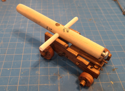
With the "cannon barrel" sitting in place and with the hardware added (I haven't received material for the capsquares and fore axletree stays yet, and they will be added, again, after I get the barrel) I have:
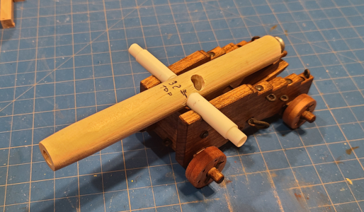
1668394066968.png
1668394126098.png

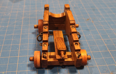
After removal of the "barrel" you can see the various hardware better:
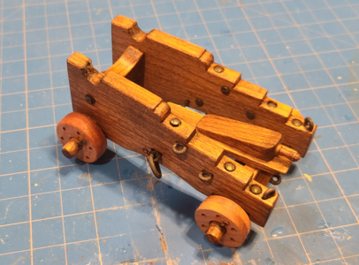
1668394361520.png
1668394373177.png
1668394388678.png
1668394402620.png
1668394416154.png
1668394429004.png

Of course the Depression Chock (Quoin) is loose at this point, and will be used to elevate the barrel to the proper angle after I have the barrel and capsquares.

Things have not all gone well, besides the blackening. One of the trucks (wheels) disappeared on me, in the trash I fear, and I had to use one of the not-so-round ones I'd made previously, and it doesn't quite match. I'll see how much that bothers me, and consider making a proper replacement.

That's it for now. I'll probably next do the same as above for the 12-pounder carriage. It's smaller, but also has lot less hardware associated with it, so should be easier. Huh - probably just cursed myself there. I'll have to keep a better eye on the remaining trucks.
 
Last edited:
Very good appearance and details executed
Just recognoized the direction of the two eyebolts at the rear - and saw, that the direction of the ring on your model is made according the drawing you are using
I am wondering, if they should be not turned by 90° to have the direction of the attached rope (with rope or a hook)
1668394402620.png BattleStation_3.JPG
 
Very good appearance and details executed
Just recognoized the direction of the two eyebolts at the rear - and saw, that the direction of the ring on your model is made according the drawing you are using
I am wondering, if they should be not turned by 90° to have the direction of the attached rope (with rope or a hook)
First, thank you very much for that. It means a lot to me.

I agree that it makes sense to turn them that way. But every source I have seen indicates them oriented as I have shown. For the Victory:
1668442160188.png
1668442550162.png
1668442739138.png

Even Boudroit on the Seventy Four Gun Ship I believe you've referenced shows them this way, and here there are two tackles connected to each loop:
1668443551334.png

And again thinking of it logically, while the direction you proposed works as well or better from with tackles from behind the gun, it would be harder to connect for those forward of the gun. I think they might tend to twist the hook and not allow it to be free.

Also, MANY carriage designs do not show loops at this rear location, while pretty much all carriages have them at the side. Perhaps the rear location was not so standardized.

Anyhow, that's my reasoning on it. I can't be 100% sure it's right, but it's enough reference for me to keep them this way. I LOVE this kind of discussion, though! :cool: Thanks for your comments.
 
Last edited:
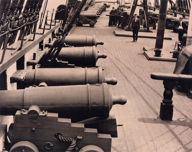
You can use your less than perfect wheel and say it was a field replace made by ships carpenter after original was damaged in battle!

I am sure there is a prototype for most everything we do in model building.
 
You can use your less than perfect wheel and say it was a field replace made by ships carpenter after original was damaged in battle!

I am sure there is a prototype for most everything we do in model building.
Or even just the existing wheel smoothed out after the battle damage! I'm telling myself the same thing about some of the imperfections. Thanks! :)
 
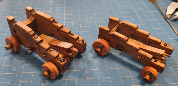
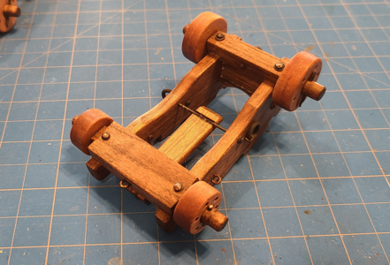
For the 12-pounder carriage, I inserted temporary "bolts" in place, holding the four main parts of the carriage and spacing them properly, rather than drilling and adding these afterwards. This kept my spacing correct without worry, but I still had to make sure the axletrees were square and everything fit properly on my flat surface:
1668455935820.png

The assembly was similar to the 32-pounder carriage, so I'll just show the finished product (less capsquares and stays, to be added later). First with the dummy barrel replacement for fit purposes:
1668456949744.png
1668456962796.png

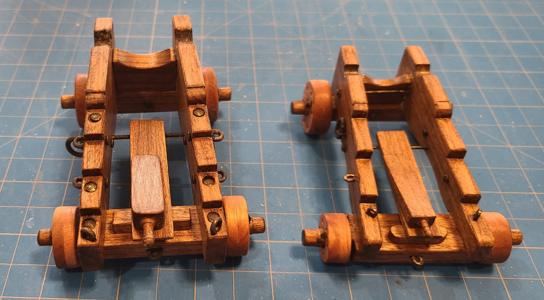
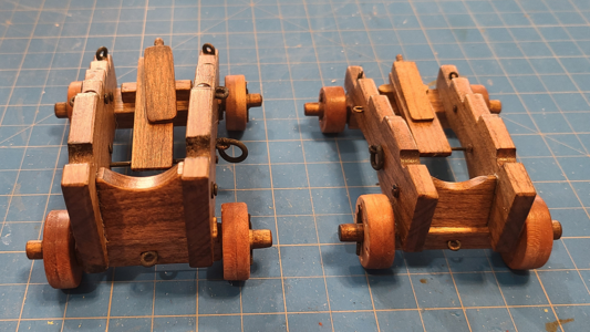
Then with the carriage itself, but compared to its big brother 32-pounder (the 24-pounder carriage on the HMS Victory was identical, BTW):
1668457019663.png
1668457050739.png
1668457064693.png
1668457079764.png
1668457099336.png

Again, the brass did not color well, and I'll correct all of that when I'm done with all of the hardware and have the barrels mounted.

Looking at the photos, I realize a made some errors (surprise, surprise): I installed the front stays bolts in place, whereas I should have waited until I install the axletree stays. I'll work on that when I get the material for the stays and capsquares.

A worse error: Somehow, I laid out the trunnion location on the 12-pounder carriage incorrectly. It is supposed to be 12" back from the front, like the 32-pounder, to the centerline of the trunnion. Mine is closer to 15". Must have been a layout error, maybe using the edge of the trunnion instead of the center. At this time, I'm not going to correct this, as it would require ripping everything apart (in case I could reuse some of it), making new brackets, etc. I'm hoping it will be less noticeable with a barrel in place. Or I'll just say that the ship's carpenter repaired the brackets on this carriage, and there was a weakness in the wood in the standard location, so he moved it a bit. And the captain never noticed. And it worked just fine. :rolleyes:

I placed my resin ruined and incorrect 32-pounder barrel in place to get a feel for what it will look like:
1668457605131.png
1668457623078.png
I also have to put iron straps around the ends of the axletrees, just outside of the wheel/truck retainers, but I'll do that last.

Now to make barrel design corrections and find a place to make them for me. My son is still unable to, having just moved into a new house and being occupied with non-fun stuff. I'll post again when I get the capsquare and stay material; still not sure how best to make those, but I'll work it out.
 
Great progress on the build, can't wait to see the final photos down the road.

Kurt
Thank you, Kurt. I can't wait to see them either!

BTW, I clicked on the link to see your Blandford Build Cross Section (I love larger scale builds), but it said I didn't have permission. Is this a private build or something?
 
Thank you, Kurt. I can't wait to see them either!

BTW, I clicked on the link to see your Blandford Build Cross Section (I love larger scale builds), but it said I didn't have permission. Is this a private build or something?
I think the admins have moved it to storage area, due to me not working on it in over a year.
 
I hadn't progress very far on my build, just started building frames when I ended up packing all tools and things up for a move two years ago, and then it got moved for some reason.
 
First, thank you very much for that. It means a lot to me.

I agree that it makes sense to turn them that way. But every source I have seen indicates them oriented as I have shown. For the Victory:
View attachment 340662
View attachment 340663
View attachment 340669

Even Boudroit on the Seventy Four Gun Ship I believe you've referenced shows them this way, and here there are two tackles connected to each loop:
View attachment 340670

And again thinking of it logically, while the direction you proposed works as well or better from with tackles from behind the gun, it would be harder to connect for those forward of the gun. I think they might tend to twist the hook and not allow it to be free.

Also, MANY carriage designs do not show loops at this rear location, while pretty much all carriages have them at the side. Perhaps the rear location was not so standardized.

Anyhow, that's my reasoning on it. I can't be 100% sure it's right, but it's enough reference for me to keep them this way. I LOVE this kind of discussion, though! :cool: Thanks for your comments.
You convinced me completely - it makes sense when you use the eyebolts for the gun tackle and the same also for pulling the guns backwards
The top-view drawing of the tackled carriage is explaing everything. Interesting is the fact, that the tackles of the guns in real are connected to different eyebolts on the sides of the carriage......
Many Thanks for your time to make this clear to me
No problem. I recently found a photo showing the eyebolts as you first showed. So either they were also mounted that way, or at least someone thought they were. Another thread I read felt that they shouldn't be there at all, based on historic information, and there certainly are enough other eyebolts in other locations. But it only makes sense that there would be variations, even modifications once on board, to suit the sailors using them as well as the captain and his carpenter.
 
As the title states, this thread started out being about only the HMS Victory's 32-pounder gun, and I later expanded it to include the long 12-pounder gun from the Victory. In a recent search for gun information on the web, I happened upon the USS Constitution Museum's Modeler Resources page. Such a great wealth of information on this page about the Constitution! Anyhow, the differing design of the gun barrels on this ship, especially the American model, and the differences in the carriages for the gun as well, have caused me to expand my build to include one of the 24-pounder guns. I've chosen the American 24-pound barrel, which is a bit shorter than the English design, along with its shorter carriage, as shown on 24-Pound Gun Barrel - American Type and Gun Carriages for 24-Pound Guns.

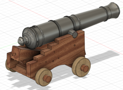
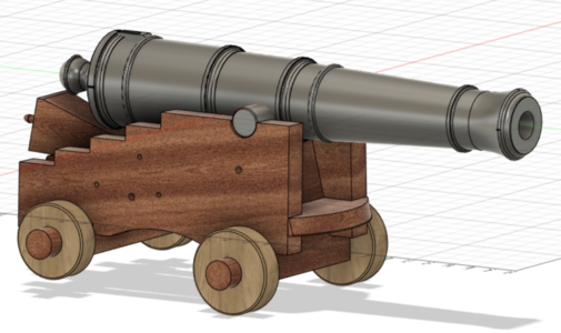
Like the previous two guns, I drew this one up using Fusion 360. I didn't bother adding all the eyes, rods, bolts and other hardware for this one; that takes a lot of time, and doesn't help me, or anyone, as a modeler. But the drawing will still have all the sizes and shapes for construction, which is what I'm after. The 3D model then looks like this:

1668965718254.png
1668965777802.png
The carriage drawing referenced actually has 3 carriage designs shown: an English style, which is 6" longer to accommodate the approximately 12" longer English barrel (18 of these onboard), the 25" high carriage for the American barrel (6 onboard) and the 27" high carriage for the American barrel (6 onboard). I chose the 27" high carriage and American barrel for my build, as it is most different from the Victory's guns.

The differences in carriage design, in particular, when compared to the Victory's carriages, are interesting:
  • The Constitution's guns have bumpers on the front of the carriage; Victory's do not.
  • The side brackets are more highly angled out toward the rear on the Victory.
  • The side brackets slope inward toward the barrel by 3/4" each side on the Constitution, while brackets are vertical on the Victory.
  • The steps in the top of the brackets are cut perpendicular to the brackets on the Constitution gun, while parallel to the axtrees on the Victory.
  • Likewise, the Capsquares on the Constitution gun run perpendicular to the trunnion axis, while the Victory's run parallel to the brackets.
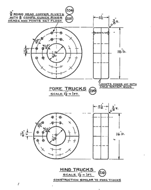
  • The Victory's trucks are 6" wide, made of two pieces held together by 6 large iron clenched bolts, while the Constitution's are 5.5" wide and held together by twenty 3/8" copper clenched rivets.
  • The Constitution uses a combination of hex and square bolts for assembly while the Victory uses more forged heads and rods with slots and tapered keys. Both hard to duplicate or purchase in 1:20 scale, unfortunately.
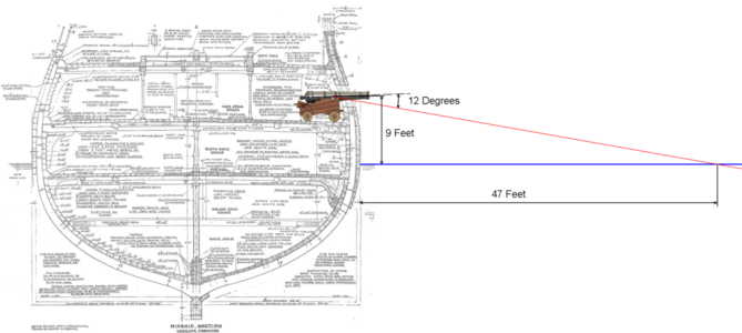
  • The most outstanding item, to me, is the Constitution's oversized Depression Chock (Coin/Quoin). It looks way too large to me. In the barrel position shown on the drawings, and in the view above, considering the deck angle, the barrel would be pointed fairly close to horizontal, with not much reason to go much lower. Yet, with the quoin pushed in, the drawing notes the barrel can be lowered an additional 12 degrees.
Concerning the last point above, I took a cross section of the Victory from this same site and superimposed the above gun and angles and came up with this:
1668969258981.png
On the sloped gun deck, the barrel in the position shown on the drawings ends pointed up about 2 degrees from horizontal, and about 9 feet above the water line. When pointed downward the specified 12 degrees by pushing the Quoin fully inwards, the barrel would be sighted at a point on the waterline only 47 feet from the side of the ship. This seems unnecessary, to me, to be able to aim that closely. Another reason that, to me, the Quoin seems to high in the rear.

I'd love to hear what all of you think concerning this.

Also, if there's any interest, I'd be happy to post PDFs of all the carriage views; all the dimensions are shown ono the above referenced PDFs, but this would be all drawn to scale, my current scale of 1:20 (easily copied and increased or decreased in size to your desired scale).
 
Last edited:
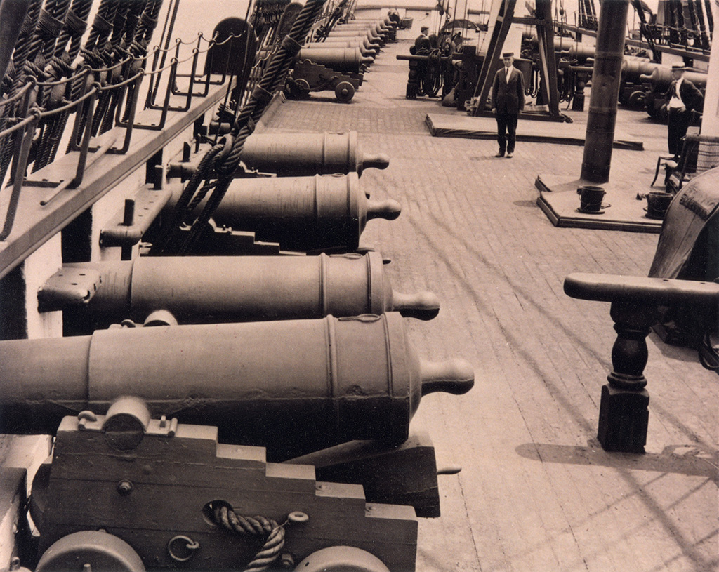
I have the same (subjective) impression - the quoin looks not correct - too high hat the rear

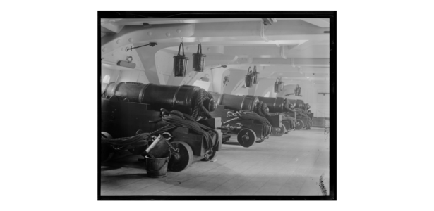
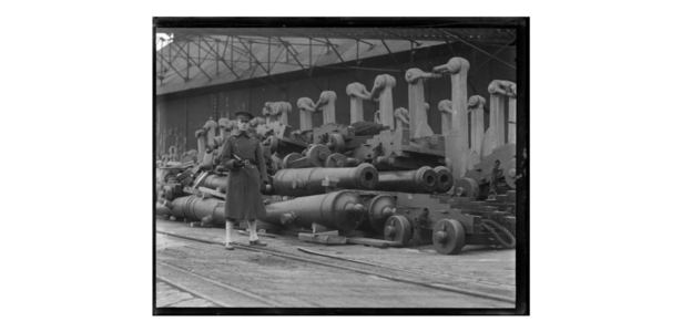
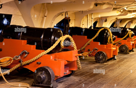
but looking at this older photo ???

1433_2548232crop.jpg


A lot of photos you can find here:


Download (2).png

Download (3).png

Download (4).png

Download.png
 
I have the same (subjective) impression - the quoin looks not correct - too high hat the rear

but looking at this older photo ???
My feelings exactly. Thanks for the great sources. I also found another photo on Alamy that you can zoom in on:
1669045950727.png
A couple things are notable here:

The quoin on the first carriage looks identical to the drawings, except it is mounted upside down. The quoin on the second looks a bit smaller, based on the fact that it is shoved in further towards the front of the gun, yet the gun is at about the same angle. I have seen photos somewhere (Victory?) that showed a quoin in place, and another smaller quoin laying on its side beside the first, which kind of makes some sense. Although now, in looking through a bunch of photos and video, I find that many/most of Victory's guns have the single quoin slipped in beside the bed, with no quoin under the gun, so I may be thinking of that instead

Also notable is that the first carriage has a more standard 6-bolt pattern on the trucks, while the second has the 20 copper bolt pattern as shown on the drawings. It also confirms what I thought was an error in the bolt spacing: the bolts on both the inner and outer row are not spaced evenly, but in a very unusual pattern, which the drawing specifies:
1669046217128.png
I'm currently layout the pattern out in Fusion 360 to figure out how best to drill them in my trucks. It's hard to lay out accurately, even in 1:20 scale. I'm thinking X-Y coordinates at this point on my Proxxon compound table, but we'll see. That's a lot of holes (80 in all for four trucks), each with separate X-Y coordinates.

Anyhow, thanks again for your participation and comments! :)
 
Since I was discussing the trucks and their unusual bolt pattern, I decided to go ahead and make them for the Constitution carriage. I don't think I mentioned it previously, but I had problems laminating the two 3" scale thickness pieces of wood to make the 6" wide trucks. My first attempt placed the two pieces underneath a couple pounds of weights, assuming they would stay put, but some force of the Universe made one piece slip off to the side of the other, spoiling the piece. By then, I'd decided to do the 12-pounder carriage, so needing twice as many trucks, I made a new piece, made sure it wouldn't shift, glued it with white glue and placed about 3 pounds of weight on it. The next morning I found that despite the weights, the water-based glue had caused the wood to distort, leaving gaps at the end. What a pain.

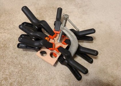
I was going to be certain that didn't happen this time. I took the two pieces for the Constitution trucks, laminated at right angles and glued with white glue, but used a better clamping method this time:
1669089124893.png
The pieces with holes cut out are previously used pieces that I used to simply protect the stock used for the trucks.

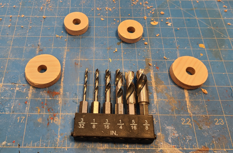
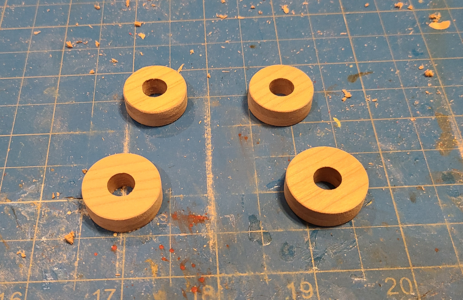
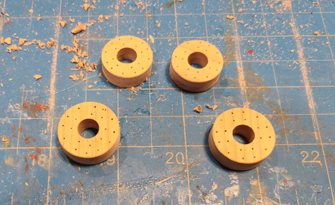
I used the circle cutter pictured in post #6 here to cut the circles. I did something different, though, this time. The 32-pounder carriage has axles about 5" in diameter, which works out to 1/4" in 1:20. But the circle drill drills a hole slightly under this. So pre-drilled the holes slightly undersize to the circle cutter diameter, keeping it from wobbling. But when done, I had to then re-bore the holes to 1/4". Drilling in steps like that don't make as neat a hole as brad point drills do. And for this Constitution trucks, I needed a larger axle 5/16" in diameter. So I drilled the axle holes on my Proxxon drill press using shorty brad point drills (GREAT for use with the Proxxon since its distance from chuck to vise is limited), to have nice, square and neat holes. I knew the circle cutter would not be that concentric, due to its smaller drill, but if the circles were oversized, I could sand them down

This pic shows the out-of-round circle truck blanks with their nice neat 5/16" holes and the brad point drills I used:
1669089676221.png

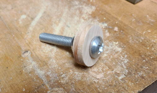
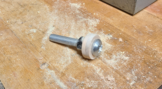
I got a 5/16" machine screw with nut and washer to chuck up the trucks for "turning" in my electric drill:
1669089749255.png

And then, my patented sanding/rounding procedure.
1669089812822.png
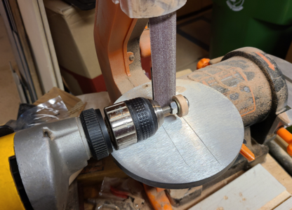
Running the drill in a normal clockwise direction increases the relative speed between the outer diameter of the truck and the sanding belt. I run the drill at a fairly slow speed, carefully held away from the belt and parallel to it, then slowly move the truck to make contact with the belt. Since the trucks were very out-of-round, I was careful not to just apply force against the belt, which from my experience results in the drill "bouncing" and staying in contact with the belt, and not eliminating the eccentricity in the truck. Instead, I just let it touch the parts of the truck which are further out, and not touching the rest, until it is both round, and the correct diameter. It then looks like this:
1669090023482.png
After a little rounding of the corners and smooth sanding the outer surface.

After sanding and rounding all the trucks, they came out a lot more round than they started, and are the right size:
1669090907853.png

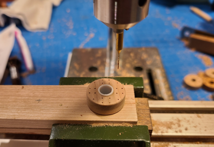
I then set up the drill press on a piece of scrap wood, and carefully drilled a 5/16" hold for mounting the trucks on. I super-glued a piece of 5/16" plastic tubing into it to provide a a mount and pivot for the trucks. I then used Fusion 360 to draw the trucks up using the bolt pattern shown on the Constitution drawings, and made a Body. Then I reduced the body in size to 5% of its original size, and made 2D drawings with dimensions from the center to each hole in actual millimeters. Note that I never moved the drills X-Y axis compound table and changed the drill bit to a 0.6mm bit. I was then sure it was centered over the truck's axle hole, and could use the calibrated dials (1 revolution = 1mm, 1 mark = 0.05 mm), to move to the proper location for each of the 20 holes per truck.
1669090436928.png
I held the wheel from rotating during each drilling. After drilling I had:
1669090500938.png
When taking the above picture, I realized I had missed a hole on one of the 16" trucks. I had also mis-drilled a hole on one of the 18" trucks, so drilled a correct one as well. I later filled the wrong hole with white glue and sanding dust (I had lots, after all). It was easy to get the 16" truck back into the correct location: I just set the drill press (with center unmoved) to the correct location for a known hole, rotated the truck until it matched that hole, then changed the settings to the new hole. This system worked out very well, and wasn't as time-consuming as I thought it would be. It was easy to get confused, though, so I kept going back to zero, rather than relying on my previous locations setting.

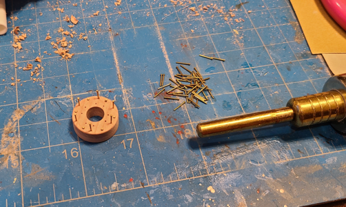
I partially inserted 0.6mm brass nails (from Dry-Dock Models) into each truck, every other nail on a row, and then using a nail pusher to seat the nails properly (although I stopped before going flush; I didn't want to over-push or make marks on the wheels):
1669090839283.png

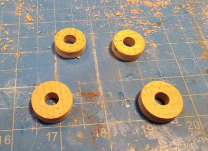
After inserting and pressing down all of the nails, I turned each truck nail-side-down on a large piece of polished steel, placed a wood scrap on the top, and used a hammer to bring the nails flush with the surface, for the finished trucks:
1669091015414.png
Not all of the nails look flush, but they are; I got some distortion in the wood surface by hammering them in that makes them look not quite flush. But I think they still look good, and will look better with stain and finish.
 
Last edited:
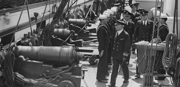
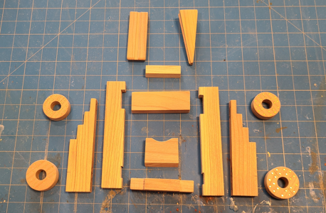
I've been making progress on individual pieces for the 24-pounder Constitution gun. Process the same as posted above, so only a pic of carriage's blank parts:
1669580201042.png
I don't have the holes for eyes and such drilled yet; still deciding exactly how to make the various eyes, bolts, nuts, clenches, etc. Also need to make the axles to go into the axtrees, but I need larger cherry dowel stock for that, which I will be picking up on Wednesday.

I thought the above was posted, but appears it wasn't. Posts in progress look the same as completed posts here, and it can be confusing.

Again continuing, I've added the bumper, which was fun to build: Slanted back at a 14 degree angle, with sides slanted roughly 1.5 degrees out toward the rear and 1.5 degrees in toward the top. Added the handle to the quoin. Also the curved areas at the bottom of the brackets and most of the holes and countersinks for bolts, eyes and such:
1669695307366.png
 
I've now drilled out the axtrees for the axle portions of them, which I will be turning from cherry dowels. The diameter at the trucks/wheels is too large to drill, so I will be turning the inserted axles down to 1/4", so the holes are now drilled to 1/4".
1669756728038.png
I also glued the transom to the fore axtree to make assembly easier. I may glue the bumper in place before assembly as well, for the same reason; due to the tapers, the bumper can't be inserted afterwards.
 
Last edited:
Back
Top