17th Century Ship Design and the Sovereign of the Seas (1637)

Background (continued)

Accuracy of Early 17th Century Ship Plans​

A present-day builder (or modeler) attempting to reconstruct a ship from 17th century plans would likely be frustrated. These plans are inaccurate by current standards. They are also incomplete, so building a replica of the Sovereign as originally built would be challenging even if we had the original plans for it. In fact, even a contemporary builder would struggle with this.

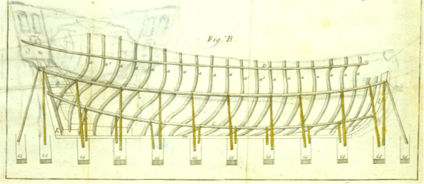
Lavery has noted that one reason seventeenth century plans are incomplete is because they did not show the frames at the ends of a ship. The result was that builders had to interpret the shapes here on their own, and two builders working from the same plans might come up with different shapes. (Lavery 1670, 26) More recently, Endsor (Endsor 2020, pg 208) has described a method of working out the shape of a ship’s aftmost frame (this is called the fashion piece). This method could also work at the bow. It depends on using waterlines, which were not in use in the Sovereign’s time, but the “waterlines” used in the method Endsor describes may have been forerunners of the waterlines later used to describe the shape of an entire ship. Whether this method was used in the early 17th century is not certain. These shipwrights could have shaped the relevant frames in the shipyard using the same methods shipwrights used before plans were drawn.

The previous paragraph alludes to another difficulty. Early 17th century plans were drawn using relatively crude methods. This even applies to the Treatise’s methods. It describes the hull’s shape by using only three rising lines three corresponding narrowing lines. The waterlines and buttocks seen on later plans, and that are used to fair a ship during design, had not yet made their appearance. Waterlines are first mentioned in Deane’s Doctrine of 1670 (though not shown on any of his drawings). (Lavery, The Ship of the Line 1984, 13) Buttock lines came into use later. In the meantime, ships had to be faired during construction. This was usually done with an adze.

A third difficulty arises because the radii of the arcs used form the outline of the midship bend were, in the Sovereign’s time, used for all of the frames along the entire ship. The frames at the bow and stern are too compressed to allow this, which caused “bumps” in the hull. Shipwrights probably removed them at the time the ship was built by fixing battens to the hull and trimming off the excess with an adze. (Lavery, Deane's System 1670)

Then, too, the process of ship design was still bound up in the tradition of designing a ship “by eye” and experience so, at first, there was little pressure to draw refined plans. As late as 1665, an overseer of a ship under construction apologized to the Navy Board for the poor quality of the plans he sent them, saying “Would have presented it in better form, but there are no workmen about there who understand the manner of doing it.”(cited in Lavery, (Lavery, The Ship of the Line 1984, 7)) This approach was wasteful, expensive, and produced ships that did not always perform as desired. It was later abandoned.

Another reason for the inaccuracy of 17th century plans is that shipwright’s calculations were often inaccurate. The Treatise often computes numbers to two places to the right of the decimal, giving the impression that 17th shipwrights planned some parts of their ships to an accuracy of at least one1/100 of an inch. This is unlikely. Limits imposed by 17th century construction techniques limited how accurately ships could be built. Accuracy was also limited because ships’ timbers unpredictably shifted during construction (this will be discussed further in the next section), so some crucial dimensions of the ship that was actually built were different from those shown on the plans.

Shipwrights knew this, and this may have contributed to why they did not seek a high degree of accuracy in their computations. The shipwright Jonas Shish computed his narrowing lines at the ship’s aft end to only within a half inch in his 1674 treatise, “The Dimensions of the Modell of a 4th Rate Ship”, and to only to within an inch for its fore end. (Endsor 2020, 117) By modern standards, these are massive computational inaccuracies. However, they could be corrected with an adze, and it was routine to use one on the frames to ensure that the planking ran along a smooth surface. (Fox, Personal Communication)

Greater precision in mathematical results may also have been avoided because performing even simple arithmetic, like multiplication, was tedious. Shipwrights often rounded their numbers, sometimes unpredictably, to simplify their calculations. The Treatise provides an example. Its author reduced the rake of the inner face of his stem by two inches to produce an even number of bends fore of the midship bend. Shipwrights also made mistakes in their calculations, which was easy to do because they had to perform so many calculations. Since there were no rigorous institutionalized review processes, these mistakes often went uncorrected (we will discuss an error that Phineas Pett made when we come to the section on the midship bend). The shipwright William Sutherland may have been taking a jab at Edmund Bushnell when Sutherland said that some shipwrights joined up the arcs on their bends with an adze[1] instead of careful arithmetic

The scale at which shipwrights drew their plans could be another source of error. Plans were usually drawn an 1:48 scale (¼ inch at this scale equals one foot), but some shipwrights used smaller scales. The Treatise’s author cautions against this saying; “there are many good artificers who can plot a ship well and build a ship also, that if their work be compared with their plot you will find them very little agree…” “For if they trust to a small scale, which many times is not above the 10th part of an inch for a foot, divided into 12 parts for every inch, and if they mistake but the 100th part of an inch upon the scale it must needs produce an error of an inch in the ship….”[2]

Drawing itself was non-trivial, particularly when ink was used. Seventeenth century writing and drawing was typically performed using a goose quill, though Queen Elizabeth preferred swan quills. Ink was either iron carbon- or iron gall-based ink. The former was made from soot, and the latter from galls, which are tumor-like growths that result from injury or irritation of a plant. Oak galls were most commonly used. (Leedham-Green 2022) Both types of ink were prone to smear, and both were homemade. Recipes for iron gall ink varied, and were time-consuming. Isaac Newton offers his recipe, in a short piece entitled “To make excellent Ink (Newton c. 1669-1693, 23):

“℞ 1/2 lb of Galls cut in pieces or grosly Beaten, 1/4 lb of Gumm Arabick [gum Arabic is the hardened sap of acacia trees] cut or broken. Put ’em into a Quart of strong beer or Ale. Let ’em stand a month stopt up, stirring them now + then. At ye, end of the month put in ℥1 [℥ is the symbol Newton used for “ounce”] ℥1 1/2 of copperas (too much copperas makes ye ink apt to turn yellow.)[copperas is crystals of hydrated iron sulfate. It is more commonly called “fools gold”] Stir it + use it. Stop it up for some time with a paper prickd full of holes + let it stand in ye sunn. When you take out ink put in so much strong beer + it will endure many years. Water makes it apt to mold. Wine does not. The air also if it stand open inclines it to mold. With this Ink new made I wrote this.”

Even the paper could contribute to inaccuracy. It was rag paper, it was not smooth, and it absorbed ink. To prevent this, it was treated with size, a gelatinous substance made from the hooves and skins of animals, and applied to the surface after the paper had been removed from a mold, rather than mixed with the pulp as it has been in later years. (Leedham-Green 2022) Vellum was the preferred medium on which to draw plans. It was made from animal skins and tended to be greasy. This was combatted by rubbing a coarse substance into it. This substance, called “pounce,” was usually powdered pumice and/or cuttle-fish bone, though crushed egg-shells mixed with powdered incense, and a mixture of alum and resin were also used.

The picture that emerges when we consider the accuracy with 17th century ships were planned and built is one of naval architecture in its infancy. It is limited by its tools, and its traditions. That would change by the century’s end. By this time, shipwrights of one country or another had solved most of the major problems that existed when the century began. Indeed, the 17th century may be the most important century in the entire history of the European sailing warship. I. (Howard 1979, pg 89)

References​

Barker, Richard. 1994. "A Manuscript on Shipbuilding, Circa 1600, Copied by Newton." The Mariner's Mirror. 80 16-29.

Endsor, Richard. 2020. The Master Shipwright's Secrets. New York: Osprey Publishing.

Fox, Frank. Personal Communication.

Howard, Frank. 1979. Sailing Ships of War 1400 - 1860. New York: Mayflower.

Lavery, Brian. 1670. "Deane's System." In Deane's Doctrine of Naval Architecture, 1670, by Anthony Deane, 128. Annapolis, MD: Naval Institute Press.

—. 1984. The Ship of the Line. Vols. Volume II: Design, Construction and FIttings. Londin: Conway Maritime Press.

Leedham-Green, Elisabeth. 2022. English Handwriting Online 1500-1700. January 4. Accessed January 4, 2023. https://www.english.cam.ac.uk/ceres/ehoc/intro.html.

Newton, Isaac. c. 1669-1693. The Newton Papers, Laboratory Notebook, MS Add. 3975.


[1] Sutherland’s specific quote is “And not to rake in the ashes of some preceding builders that has verified the old proverb, in making the addice [adze] the reconciling mould, there be several at this day that will engage to build a ship with little assistance of such an instrument"(cited in Barker (Barker 1994, pg 40))
[2] All quotations from the Treatise are from a publicly available version in which the English has been modernized, and to which punctuation has been added.
 
Last edited:
From here on, I will be discussing the Sovereign of the Seas and, in a week or so, I'll post some discussions of artwork. Part of these discussions will be about a painting that is housed in the Boston Museum of Fine Arts.

For the upcoming sections, please download the painting of the Sovereign of the Seas at:

https://collections.mfa.org/objects/32448

There is a long and complicated story behind this, part of which involves some rather extraordinary licensing fees. In a nutshell, the museum’s copyright policies, and therefore, whether I can show it on SOS, are ambiguous to my non-legal mind, so I contacted them. Since I’m not a lawyer, I also found their reply ambiguous. Therefore, I’ve decided not to show this painting.

This is not much of a loss when it comes to showing the painting in its entirety. I don’t refer to it that often. However, there is a difficulty when it comes to showing parts of the painting and/or labelling those parts. The museum tells me that I “may not crop, overprint, manipulate, or otherwise alter any images from the MFA’s website.” Most of the images of the painting I would like to use do exactly the things the museum says I cannot do.

Because of this, I will (in some cases) substitute another portrayal for the Boston museum’s painting. In other cases, I will substitute my own drawings for these parts of the painting. They are relatively crude. They will, however, be clear enough to illustrate the points I am trying to make. You may want to nevertheless download the pictures for your own personal use, and so you can see the parts of the original work I am discussing.
 

Section II: Data Sources​

Whose Ship Should We Build?​

The first question we must answer when attempting to reconstruct the Sovereign is “Whose dimensions for it should we use?” There are contemporary sets of them. The present subsection evaluates them using information supplied by Frank Fox in a series of personal communications.

The first set of dimensions for the Sovereign [1] is contained in a letter drafted in April of 1635 by a committee consisting of Phineas Pett, John Pennington, Robert Mansell, and John Wells. This committee examined Pett’s plans and submitted a proposed list of the important dimensions to the King. The second is a list of dimensions that John Pennington submitted to the King ten days later. Pennington’s dimensions are used in at least two relatively recent sets of plans for the Sovereign.

The reasons some have used Pennington’s dimensions are ultimately based arguments made by W.G. Perrin, (Perrin 1918) who concluded that Pennington’s dimensions were used. He reached this conclusion by comparing Pett’s and Pennington’s proposed dimensions to measurements taken of the Sovereign itself, while it was being built. Perrin cites a document from September 1637 as the source of these measurements. (Perrin 1918) They are:

  • Length of the keel: 127 feet
  • Depth in hold: 19 feet 4 inches
  • Molded Breadth: 46 feet 6 inches
These dimensions, as well as those given by Pett and Pennington, are shown in Table 1. Based on this information, Perrin concluded that Pennington’s list “seems, from the fact that the tonnage is quoted in the contemporary lists as 1522 tons, to have been the one finally adopted, though with slight modification.” (Perrin 1918, xcii -xciv)

Table 1. Information Used for Perrin’s Tonnage Calculations


Dimension
Actual Measurement
Pett’s Dimensions
Pennington’s Dimensions
Length of Keel
127 feet127 feet126 feet
Depth in Hold
19 feet 4 inchesReported by Pett as 18 feet 9 inches*Perrin Reports this as Not Given
Molded Breadth
46 feet 6 inches46 feet 2 inches46 feet 6 inches
Tonnage
15221466**1522
*The depth in hold that Pett listed is actually incorrect. Section III, “The Midship Bend,” will show the mistake he made when he reported it, and will provide the correct depth.
**We will later see that because Pett’s depth in hold is incorrect, his calculation of the Sovereign’s tonnage is also incorrect.


The “slight modification” Perrin mentions is the keel’s length, which agrees with Pett’s dimensions, not Pennington’s. Contrary to what Perrin says, this modification is not slight. It has a substantial effect on a ship’s tonnage.

That the Sovereign’s tonnage agrees with Pennington’s dimensions is a key part of Perrin’s argument. Tonnage is a measurement of how much room there is inside a ship. It was originally developed to determine how many wine barrels a ship could carry. These barrels were called “tuns.” The formula for tonnage that was used in the Sovereign’s time is shown in Equation 1 (in this equation, and the following text, I refer to the depth in hold simply as the depth).


Equation 1. Formula for Calculating Tonnage
1720617831862.png

Perrin does not describe whether he performed the following calculation, but we can arrive at the tonnage he accepted by using Equation 1 with Pennington’s dimensions. In doing so, we will, like Perrin, believe that the depth was not given. Therefore, we will assume, as Perrin did, that the 19 foot 4 inch depth measured on the Sovereign was also Pennington’s proposed depth. Putting this depth into the equation along with Pennington’s dimensions for the keel and breadth, yields the same tonnage, 1522, that was measured on the Sovereign.

Because Perrin did not think the depth was given in Pennington’s plans, he did not calculate the depth implied by them. The depth can be calculated by rearranging Equation 1 to yield Equation 2:


Equation 2. Formula for Calculating the Depth in Hold
1720617796204.png


Plugging in Pennington’s dimensions into this equation gives us a depth of 19 feet 5 ¾ inches.[2] This is not the depth Perrin assumed. It shows that Perrin was incorrect when he assumed Pennington’s proposed depth was the same as that measured on the Sovereign.

Pennington’s implied depth must be calculated using the assumption that the Sovereign had a keel that was, as he specified, 126 feet long. It did not. This provides additional reasons for not using Pennington’s dimensions. If we insert his implied depth and the keel length actually measured on the Sovereign (127 feet) into Equation 1, we obtain a tonnage of 1534, which is clearly different from both the Sovereign’s actual tonnage and Pennington’s proposed tonnage. This tells us that the identity between the actual tonnage (1522, and which is based on a keel length of 127 feet) and Pennington’s proposed tonnage (which is also 1522, but depends on a keel of 126 feet) is just a coincidence. After all, there are many combinations of numbers we can multiply together to obtain 1522. The key part of Perrin’s argument is thus problematic.

Perrin apparently also believed Pennington’s dimensions were used because the breadth suggested by Pennington is the same as the breadth measured on the Sovereign. Ironically, the fact these two dimensions are the same is evidence that Pennington’s dimensions could not have been used. Large 17th century ships always grew broader when they were built. Twenty seven of the 30 ships in Samuel Pepys’ “Register of Ships” are listed as being broader than designed, and William Keltridge, in a manuscript entitled “William Keltridge His Book Aprill 24th 1675”, tells us that the remaining three ships were also broader.[3]

Peter Pett, the Sovereign’s builder, referred to this increase in breadth as “falling out.” Thus, when asked in 1664 to examine the proposed dimensions for a new ship, he commented “Yr breadth of 35 feet 8 inches is well; I should have made it 36 but that I beleeve they will fall out 4 inches.” (Fox) Falling out happened because the posts used to shore up the large frames (Figure 2) bent before the frames could be fastened together by the deck beams. It may have been part of the reason why, in the 1680’s, the shipwright Sir Phineas Pett (a descendant of the Sovereign’s designer) commented that “no ship” could be truly built according to plans. (Hemingway 2002, pg 54)

Falling out was not limited to when a ship’s was first built. It could occur any time the frames were shored up with posts. Their bending caused the Sovereign’s breadth to increase by about 2 inches during its 1659-1660 repair, and by about another 4 inches during 1684 repair. These increases happened even though Robert Lee, who oversaw the later repair, said that did he not alter the ship’s frames, and they had not been altered since the ship was initially built.

The inevitable occurrence of this broadening makes it impossible that Sovereign was built according to Pennington’s dimensions. His proposed breadth is 46 ½ feet. If these proposed dimensions had been used, the breadth would have widened to greater than the 46 ½ feet that were measured on the Sovereign. On the other hand, a ship built according to the designed breadth listed in Pett’s plan, 46 feet 2 inches, could have easily widened to the measured breadth of 46 ½ feet.

Figure 2 Post Shoring the Timbers during Construction

1720618127319.png
Note: Drawing from Sutherland (Sutherland 1726)

Falling out also has consequences related to the depth that Pennington’s plans imply. The shifting of the timbers during construction causes the breadth’s height at the midship bend to increase. The depth was measured at this height, so an increase in the breadth’s height increases the depth. We therefore expect the depth that was measured on the Sovereign to be greater than its designed depth. It was (the correct depth will be provided in the section on the midship bend). If Pennington’s design had been used, his depth would have had to decrease from his implied value of 19 feet 5 ¾ inches to 19 feet 4 inches. That it would have to decrease means that Pennington’s design could not have been used.

There is yet another problem with Pennington’s design. He increased Pett’s deck heights, 7 feet for the first deck, and 7 feet 3 inches for the second and third decks, to 7 feet 6 inches for all the decks. Such high decks would have made the Sovereign even less stable than it already was. Yet, this height was not commented on by the ship’s many critics who would certainly have noticed this. Indeed, and as noted earlier, the Masters of Trinity House had already objected to Pett’s even lower heights.

We should also recognize that that the King’s notation on the Pennington’s plans simply says “Dimensions of Pennington's Model for the Great Ship, 17 April 1635”. This merely acknowledges that the dimensions were received. On the other hand, the King’s handwriting on the document containing Pett’s original plans says “Dimensions resolved on for the Great Ship, 7 of April 1635” [italics added], which implies that Pett’s dimensions were the final dimensions. We also need to recognize that no historical document credits Pennington with designing this ship. All contemporary references give credit to Pett. Indeed, Pennington’s plans are never even mentioned after the King acknowledged that he received them.

Finally, and as we will note when we discuss the midship bend, the sweeps that were used for the Sovereign’s midship bend were not those that Pennington proposed.

In summary, the evidence shows that Pennington’s dimensions were not used to build the Sovereign. Rather, it points to those of Phineas Pett. This fits with the fact that history has consistently credited Pett with designing this ship. Therefore, Pett’s dimensions are the dimensions upon which the present reconstruction is based. Notice that these are the dimensions for the ship as it was designed, not as it was built. The varied and unpredictable shifts caused by the ship’s “falling out” during construction make it impossible to devise accurate plans for an “as built” ship.


Notes

[1] These two versions are in the introduction to “The Autobiography of Phineas Pett, edited by W.G. Perrin (Perrin 1918), and originally published by The Naval Records Society in 1918. It can be downloaded at https://www.gutenberg.org/files/51357/51357-h/51357-h.htm

[2] The precise figure is 19.4838 feet. When we insert this into Equation 1 we obtain a tonnage of 1534.0794 which we round to 1534. We also obtain a tonnage of 1534 if we round 19.4838 feet to 19 feet 5 ¾ inches, and then insert it into Equation 1.

[3] A copy of Keltridge’s book can be downloaded at https://repository.library.brown.edu/studio/item/bdr:6feamztx/

References​

Fox, Frank. Personal Communication.

Hemingway, James Peter. 2002. "The Work of the Surveyors of the Navy during the Period of Establishments." Doctoral DIssertation. Bristol, England: Uinversity of Bristio.

Perrin, W G. 1918. The Autobiography of Phineas Pett. The Naval Records Society.

Sutherland, William. 1726. Ship-builder's Assistant. London: Thomas Page and Fisher Mount.
 
This is fascinating information. Thank you very much for sharing your research! The list of scantlings in Keltridge is especially useful for anyone involved with a 17th century ship, be it scratch, kit designer or kit builder.
Allan
 
I ALSO AM FOLLOWING THIS WITH GREAT, GREAT, INTEREST AS I DID WITH WALDEMER MAYBE YOU TWO SHOULD GET TOGETHER COMPARE NOTES COMBINE FOR FUTURE POSTS JUST TO LET YOU KNOEW I AM A NOVICE TO YHIS SUBJECT BUT SO DEFINATLY WANT TO LEARN AS THIS FALLS INTO A LONG LOST THEME OF MINE IN MODELLING. WILL POST MORE PLEASE GUYSW CONJTINUE YOU HAVE MORE INTERESTED MEMBERS THEN YOU THINK. GOD BLESS STAY SAFE YOU AND YOURS DON
 
Hello Charlie
I am new at this and I am enjoying this discussion very much. At this point of my education I am sorry that I have nothing of substance to contribute, but some day I look forward to contributing to these discussions. I do have one question. In Table#1 you listed "Actual Measurements". What information were these measurements based on? If I missed something along the way, I do apologize.

Thanks, Bill
 
Bill, I'm sorry for the confusion. I just can't think of a better column header.

"Actual Measurements" refers to measurements actually made on the Sovereign. They were made in September of 1637. Since the ship was initially scheduled to be launched in September, its construction was probably finished when at this time. So, more likely than not, these are measurements made on the completed ship.

Oh, one more thing I did not make clear; The measurements of the depth in hold and the breadth were made at the midship bend.
 
I'm with you on the concept of "falling out" on the initial construction. Shores into soft earth, over a period of say 4 months before wales are installed, are likely to sink. What I'm wondering about are subsequent re-fits. My assumption is that, for the most part, deck clamps and most of the deck beams would have remained in-place, preventing further spread. If one were to reference the Jean Bart reconstruction in Gravelines, they can see first-hand this type of authentic frame-up:


It is early, yet. They have gotten to the level of what will be the lower main wales, and the lower battery deck.
 
Thanks, Hubac! It's not merely sinking into soft sand. The timbers supporting the frames bend. More importantly, the deck clamps and decks did not remain in place during the Sovereign's 1650-1660 repair, (I'll talk about this several posts from now) or its 1685 repair. They were ripped out and re-laid (I'll keep you in suspense bout how).
 
Building docks had timbers laid in the bottom at regular intervals, which stretched the full width, and were located at right angles to the keel. These were called ground-ways. The spaces between them were filled with shingle to prevent movement, like railway sleepers. The sides of the dock were often stepped, and were also timber-framed and reinforced. The higher level meant that shores supporting the upper part of the ship's sides did not need to be long enough to reach the bottom of the dock, so they could be both shorter, and therefore less liable to bending, and also easier and cheaper to obtain. Timber shores were an item frequently delivered into the dockyard stores, and were obviously purposely-selected timbers, not just random offcuts. Shores were spiked down to the ways with large nails, as also were the stacks of timbers, known as 'splitting blocks', on which the keel was laid.

Every time a new ship was brought into dry dock, and the water had gone, the floor was cleaned and scraped. Obviously over time the ground-ways would rot, and become softer, which would then allow some movement of the frames if these were not properly restrained across the width. An important factor here was that in the early 17th century, ships were not built in the better known fashion used in later times, where complete frames were erected; rather that the bottom planking was fitted in sequence with the futtocks, both progressing upwards in unison, with the futtocks held in place by the planking, not by longitudinal fastenings between the overlapping sections of futtocks. This was the English method; I have no information on continental methods, which may have been different. It is quite reasonable to expect that the midship frame and maybe a couple of others at quarter lengths were erected whole, but this is the subject of ongoing research, and I cannot comment on this with any certainty at present.

Ratty
 
Last edited:
A paragraph I obviously didn't write clearly enough is the one showing that these ships, "as built" were always broader than proposed. That alone is sufficient to show that Pennington's plans could not have been used. In this sense, one can propose any mechanism they would like for the data I provided about this, and the argument isn't affected. Bending of the timbers was the best one I could think of, but any other will do. I'm sorry about the confusion I caused..
 
Charlie, no apologies required; your meaning was quite clear. My post was simply to clarify the mechanism by which it probably occurred.

Keep up your fascinating postings, being read with great interest.

Ratty
 
Data Sources (continued)
The Treatise on Shipbuilding or Deane’s Doctrine?
This section continues the previous discussion of the data sources used in the present reconstruction. We will use information from contemporary works on shipbuilding when information specifically about the Sovereign is not available. This section will focus on the Treatise and on Deane’s Doctrine because both have previously been used to reconstruct the Sovereign. This section is not intended to be a comprehensive review of all contemporary works on naval architecture. Other works relevant to the present project will be mentioned in appropriate places throughout this thread.

When considering any 17th work on shipbuilding, we must remember that their applicability to the Sovereign is limited. Reliable information specifically about the Sovereign should obviously take precedence over information from any of them when there is a conflict. Conflict is expected because most of these sources describe 2-decked ships, not 3-deckers like the Sovereign. Our goal, then, is not to use as much information from these sources as we can, it is to use as little of it as we must. We will not need to use them much, but where we do will be important. We need to use them the rising and narrowing lines.

In considering contemporary works on ship design, it is important to note that shipwrights did not simply pull the Treatise or any other contemporary shipbuilding work off their bookshelf and use it like a cookbook. Each shipwright had his own way of doing things, and they simultaneously used elements like those seen in several different treatises. For example, when the shipwright Jonas Shish designed the Tyger, he used a modified version of the Treatise’s equation for the fore narrowing line of the breadth, and a method like that described by Bushnell for the fore rising line of the floor. (Endsor 2020) Deane aptly summarizes the extent of the variations among shipwrights by explaining that “these bends of timber are the greatest art which belong to the master builder, and have so much variety in them as you can have imagination in your thoughts.” Therefore, we should not expect that rotely applying any one set of design principles to the Sovereign will yield a satisfactory approximation of this ship.

We can see this by the dimensions that Pett provides (or that we can deduce from his dimensions) for the Sovereign to those that the Treatise or Deane would have us use. For example, the breadth that Pett gives us is a little more than 5 ⅔ inches larger, and its depth a little less than 6 ⅝ inches smaller than the Treatise would have us use. The Sovereign was also over 8 feet broader, and its transom 2.78 feet narrower than Dean would have us use.

The rising and narrowing lines are an exception to the “rule” against applying a single set of design principles.[1] Applying a combination of principles here would be arbitrary. I will argue here that, in the absence of information about how Phineas Pett designed his rising and narrowing lines, the Treatise supplies a reasonable set of methods, albeit with some modification.

Others have used Deane. The argument for doing so is that Deane had a connection with the Pett family. This connection comes about because Deane was likely apprenticed to one of Phineas’ sons, Christopher (Lavery 1982, 7), and Christopher, who likely worked on the Sovereign as it was being built, had to have been influenced by Phineas. This argument it is more opinion than hard evidence. That Deane had a certain teacher, Christopher, does not mean this teacher agreed with everything Phineas did. Christopher may have done things differently. Further, ships changed between the Sovereign’s time and when Deane wrote his Doctrine. These changes largely came about because of changes in the was sea battles were fought.

In the early part of the 17th century, battles were fought between single ships or small squadrons. To attack, ships fired a broadside, turned around, and then fired another. When the opponent’s ship was weak enough, they boarded it and fought a melee-type action. The idea, then, was to board a ship, not sink it. The forecastle was a prized position to take in such battles (Kirsch 1988), so it tended to be higher in older ships to resist boarders. The Sovereign’s relatively high forecastle harks back to these older ships. So does the overlaying of its decks with grating designed to hinder boarding. By Deane’s time, the style was different. Now, ships on opposing sides each formed a column and fired at each other as they passed. The term “ship-of-the-line” comes from this alignment. The idea behind this line was that ships in a line could more effectively deploy the power of their guns. (Lavery 1982) [2]The ship portrayed in Deane’s Doctrine is like a ship of the line. For example, the top of the ship is lower and broader at the bow and stern than older ships. (Kirsch 1988, 125).

We can glean a little more information about how the Treatise and Deane compare to the Sovereign by comparing their keel:breadth ratios. Consider two ships with the same breadth. The one with the longest hull (and, therefore, a greater keel:breadth ratio) can carry more guns, and might be faster. However, it is less maneuverable than ships than the ship with a shorter keel. (Howard 1979, pg 95) The keel:breadth ratio of the ship Deane describes in his Doctrine is 3.33. the Treatise describes a ship whose keel is 2.78 times larger than its breadth. The Sovereign’s keel:breadth ratio is 2.75. Comparing the Treatise’s and Deane’s 2-decked ships to the 3-decked Sovereign is something of an “apples to oranges” comparison, but the point is that the Treatise’s ship is more like the Sovereign than Deane’s.

There are other difficulties with using Deane’s Doctrine. We have already pointed out that his description of his rising and narrowing lines is probably a simplified version of what he actually did. We have also noted that his drawings show sweeps with changing radii, while his text does not describe this. Therefore, we cannot replicate these radii. These difficulties mean that we can never truly design a ship the way Deane did on his actual ships and, therefore, when attempting to apply his system to the Sovereign, we are probably designing an artificial ship.

We now turn to comparing the Treatise and Deane by comparing the shapes of the midship bends that result from their respective systems. This bend’s shape ultimately determines the shape of the entire hull so, If the midship bend is wrong, the entire ship is wrong. We will focus this text on the width of the Sovereign’s floor. It determines where we start drawing the rest of our sweeps, so wider floors mean wider bends.

The Treatise allows for a floor width between ¼ and ⅓ of the breadth in a man of war,” which is 11.54 feet to 15.39 feet in the Sovereign. Pett’s 13-foot floor is almost in the middle of this range. The width of Pett’s floor also nearly equals the 13.48 feet the Treatise describes as “fit for all kinds of shipping (this figure equals half the difference between a ship’s breadth and depth).

Deane does not provide an “admissible” range, but does say the half breadth of the floor should be 1/3 of the half breadth. This works out to be 15.39 feet for the Sovereign, which is 28.67 inches wider than Pett’s. It is at the upper limit of the width the Treatise allows.”

That the width of the Sovereign’s floor is well within the range specified by the Treatise, and equals the width that was “fit for all kinds of shipping” is noteworthy.[3] Pett previously designed the Prince Royal (1610) with a floor that was criticized for being too wide by Mather Baker and some of the other shipwrights who examined this ship.[4] (Kirsch 1988, 128) (Perrin 1918, lxxix). It would be understandable if Pett wished to avoid receiving more criticism of his floor’s width.

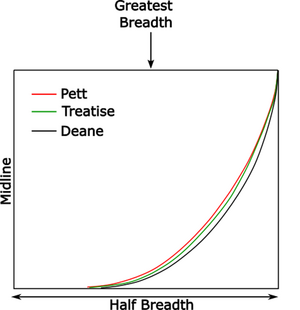
The differences between Pett’s, Deane’s and the Treatise’s midship bends are put into context when we draw them (Figure 3). Since Pett does not provide a radius for the hollowing sweep, we can only compare the bends at, and below the breadth. This is not a serious limitation for the present purposes. The two rising and narrowing lines that were most important to shipwrights are here.


Figure 3. Pett’s, the Treatise’s and Deane’s Midship Bends
1721136354154.png
Note: The sweeps’ radii in this figure were computed by applying Deane’s and the Treatise’s proportional rules to the relevant dimensions provided by Pett. The floor for the Treatise is the one “fit for all kinds of shipping.” Neither the Treatise nor Deane explicitly consider deadrise when drawing their midship bends so it is omitted from the version of Pett’s dimension shown in this figure. Deadrise is included in the midship bend of the actual plans.

Deane’s wider midship bend again illustrates that he is designing a ship that is different from the Treatise’s. It also shows that the Treatise’s system produces a bend that is more like the Sovereign’s than that produced by Deane’s system. This provides circumstantial evidence the Treatise might give us a better approximation of the shape of the entire hull, as determined by the rising and narrowing lines. This suggestion is by no means definitive but, as we go through the reconstruction, we will see that the Treatise’s dimensions are almost always closer than Deane’s to the Sovereign. Much later on, I also will summarize and extend the evidence showing that Deane’s system does apply to the Sovereign. For the time being, we need only view this as part of a dataset that tells us to prefer the Treatise to Deane.

We will take advantage of this preference by viewing the Treatise as a flexible system. This contrasts with Deane, whose system is inflexible. With it, we are forced to draw all these lines as parts of circles. The Treatise does not use any circles. It gives us methods for calculating lines that curve in a variety of other ways. This gives us a flexible mathematical framework that allows us to improve our approximation of the Sovereign’s rising and narrowing lines. For example, the Treatise has us compute the narrowing line that determines the ship’s breadth as it approaches the bow by raising certain numbers to a specific power. This power yields a ship with a bow that is not as bluff as that of a 3-decked ship. To correct for this, we can use a higher power. The result will, of necessity, be speculative, but it will be an improvement over existing plans.

In summary, and in the absence of information about how Phineas Pett constructed his rising and narrowing lines, we are practically forced to choose between Deane and the Treatise (or some similar system) for them. The difficulties with Deane practically force us to choose the latter. In choosing the latter, we are not using an unusual system. We are using a system like that described by others. The way the Treatise’s narrowing lines are computed is in some cases identical to, and in others very similar to the way they are computed in Thomas Harriot’s slightly older work. (Pepper 1981) This makes it likely that the Treatise’s methods are like those that elite shipwrights really used. This contrasts with Deane’s Doctrine. There are no contemporary references to copies of it being made for circulation. The manuscript was housed in Samuel Pepys’ library, and it therefore seems that his Doctrine (as opposed to his actual ship designs) did not influence other shipwrights. (Olaberria 2018, pg 157) [5]

We will turn to discussing the relevant artwork of the Sovereign in the next post.


[1] Pett’s description of these lines exists in a set of papers complied by Charles Sergison (1654- 1732), who had a long career with the Navy Board, his papers consist of over 100 volumes, but it has not been located in them at of the time of the present writing.
[2] This new tactic also gave rise to fleets that were divided into two types of ship. The first type, the ship of the line, could deliver and withstand heavy battering. The second type was cruisers that were designed to be maneuverable and fast. This was how navies would look until the end of the Age of Sail. The battering ships received from navies arranged this way put stresses on the hull that had not been seen before. Additional new stresses were encountered because, beginning in about the mid-17th century, ships were deployed on long voyages far from their home ports. (Barchvaror 2007)
[3] The Treatise’s author takes pains to mention that the Prince Royal’s floor does fit within its suggested proportion. This hints that the range of acceptability may have expanded between the time the Prince Royal was built and the time the Treatise was written. The floor we obtain for the Sovereign when we use Deane suggests it further expanded later on.
[4] Henry Briggs, was brought in as an independent adjudicator. (Perrin 1918, lxxix) Briggs was a Professor of Geometry at Gresham College, (J. V. Pepper 1979) which attests to how important mathematics were for building ships in this era
[5] Endsor notes that John Evelyn saw Deane’s work and called it “an extraordinary jewel.” (Endsor 2020, pg 110) The date of the entry in Evelyn’s diary shows that he saw it on January 28, 1682. It was shown to him by Samuel Pepys. Since Evelyn and Pepys were friends, Evelyn was almost certainly shown the volume in Pepys’ library. Evelyn was not a shipwright, so he did not have the knowledge to critically evaluate what he saw.


References

Barchvaror, Kroum N. 2007. "Dartmouth Revisited." The International Journal of Archeology. doi:10.1111/j.1095-9270.2007.00143.x.

Endsor, Richard. 2020. The Master Shipwright's Secrets. New York: Osprey Publishing.

Howard, Frank. 1979. Sailing Ships of War 1400 - 1860. New York: Mayflower.

Kirsch, Peter. 1988. The Galleon. London: Conway Maritime Press, Ltd.

Lavery, Brian. 1982. "Introduction." In Deane's Doctrine of Naval Architecture, 1670, 7-31. Annapolis: Naval Institute Press.

Olaberria, Juan-Pablo. 2018. Ship Design Knowledge in Early Modern Europe: Royal Yachts and the Shared Knowedge of Ship-designers and Common Shipwrights. Vol. 1. 2 vols. Southampton: Doctoral Dissertation; University of Southampton.

Pepper, John V. 1981. "Harriot's Manuscript on Shipbuilding and Rigging c. 1608-1610." In Five Hundred Years of Nautical Science 1400-1900, by 1979 Proceedings of the Third International Reunion for the History of Nautical Science and Hydrography, 204-216. London: National Maritime Museums, Greenwich.

Pepper, Jon V. 1979. "Harriot's Manuscript on Shipbuilding and Rigging." Five Hundred Years of Nautical Science 1400-1900. Greenwich, London: National Maritime Museum. 204-216.

Perrin, W G. 1918. The Autobiography of Phineas Pett. The Naval Records Society.
 

Which Artwork Should We Use?​

Overview​

It is necessary to use artwork when developing plans for the Sovereign. Only art tells us about this ship’s general features, like the number of wales and rails it had, and how their positions relate to the gun ports. It is risky, though, to attempt to propose specific dimensions for this ship based only on art. After all, artists were not shipwrights, and they were usually unaware of how ships were designed and built. Although some elite shipwrights may have artistically portrayed a ship as a means of promoting its building, they never built a ship from that art. Elite shipwrights drew plans.

There are other reasons art is insufficient for the present project. Not only is it impossible to use it for the many features (e.g., deck planking thicknesses and cambers) that are not visible on it, it is also difficult to use for the features that are visible. Doing the latter requires us to assume that the work is perfectly accurate. That is rarely the case, particularly with art of the Sovereign’s time. It was not uncommon for artists of this time to portray things that were not even there when they drew or painted a ship. We will discuss several instances of this throughout this thread, but can provide some obvious examples now. They pertain to an engraving of the Sovereign prepared by John Payne (this engraving is discussed in greater detail below). Payne shows the ship in water. It was not. It was in drydock when he saw it. Payne also shows the ship with masts, sails, rigging, and guns. None of these were present when he saw the ship. There was also no crew present to clamber along that non-existent rigging, nor were there finely attired gentlemen to adorn the Sovereign’s decks.

Admittedly, we can reasonably estimate some dimensions if we confine our measurements to objects near the ship’s middle, but measurements taken elsewhere are highly uncertain. This is partly because artistic representations of the Sovereign contain an optical illusion. It occurs as we approach the stern. The rails here are rising more rapidly than the decks. This makes it look like the decks are becoming lower, even though the opposite is true. This illusion is even noticeable on the present plans.

A more important reason for our inability to accurately measure artwork derives from artists’ use of “artistic perspective.” This perspective is a technique for creating the illusion of depth and space on a 2-dimensional surface (like a canvas). One consequence of this perspective is that objects that are further away from the artist are portrayed as smaller, higher, and closer together than objects in the foreground. You can see this by looking at how the cannons on any given gun deck are portrayed in a famous painting, often attributed to Peter Lely, of the Sovereign’s stern. Objects that lie along a curved surface are similarly distorted.

Artistic perspective presents us with challenges when we try to develop a ship’s sheer plan[1] from works of art. Sheer plans stretch out curved surfaces to make everything flat. This means that objects that look relatively close together in a painting are further apart on a sheer plan. This is a particular problem for objects at the ship’s highly curving bow. One recent set of plans for the Sovereign is an example of what happens when we do not consider artistic perspective. Its author rejects the rake of the stem that Pett gives us because it resulted in a stem that looked bigger than the stem that artwork portrays. Yet, artistic perspective tells us that this is exactly what we should expect. The problems caused by artistic perspective are not an issue with the present approach.


The Pett Painting​

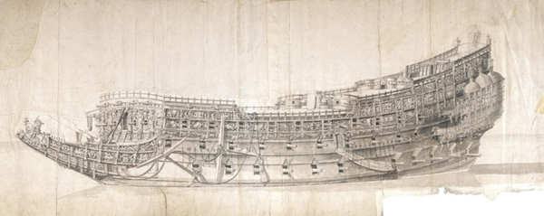
Using art to reconstruct the Sovereign is challenging because the works that portray it appear to disagree. However, we are fortunate to have a painting of the Sovereign that was prepared by its builder, Peter Pett (Figure 4). The original painting is housed in the Museum of Fine arts in Boston. The museum describes it as “Probably a presentation drawing for the ship designed by Peter Pett[2] for Charles I of England and built in 1637 but painted in “about 1635.” (Museum of Fine Arts Boston ca. 1635) The description continues by saying that “it shows the sculptures of the starboard side in some detail, drawn in, colored with tempera, and accented in gold.” The museum lists the artist as “unidentified” but “possibly after designs by “Peter Pett (English, 1610–1672)” and “possibly after designs by Anthony van Dyck (Flemish, 1599–1641)”. (Museum of Fine Arts Boston) The artist was likely Peter, who was Phineas’ son. (Fox, Personal Communication)[3] A unique feature of this painting is that it contains dotted lines that help locate the gun decks at certain places, though there are breaks in these lines that seem placed to avoid giving us too much information about how the ship was built. These lines probably represent the deck beams because the ports are too far above them to represent their tops. This conforms with how shipwrights drew their plans. These dots also make it likely that the artist was someone familiar with how this ship was built. Peter Pett oversaw building the Sovereign of the Seas, and his father was its designer, so he was familiar with it. I will refer to this painting as the “Pett painting” from now on.

Figure 4. Pett’s Painting of the Sovereign of the Seas

This figure is of the painting I previously said I won’t show.
You can find it at https://collections.mfa.org/objects/32448


The Pett painting was prepared before the King increased the number of the Sovereign’s guns from 90 to 102. It therefore does not show gun ports on the forecastle’s sides, and shows only two ports on each side of the half deck. The completed Sovereign probably had two ports on each side of the forecastle, and three on each side of the half deck.

I rely more on the Pett painting than any other depiction of the Sovereign. I do so on the grounds that the Sovereign’s builder knew more about this ship than anyone else who portrayed it. I am not aware of any published plans that are primarily based on this painting.


The Payne Engraving​

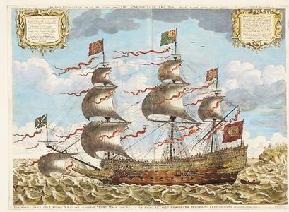
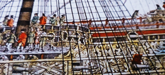
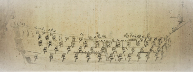
A 1637 engraving by John Payne (Figure 5) is the portrayal most often used to reconstruct the Sovereign. At the time Payne saw the ship, its deck gratings were still under construction, and were resting on temporary timbers or sawhorses. They were was, therefore, lower than they would be when the ship was finished. (Fox, Personal Communication) Several features of the engraving show this. For example, the port side of the fore end of the half deck’s grating has been lifted, but the rest of it has yet to be moved into position (Figure 6). This grating also partially blocks the door in the bulkhead at the quarter deck’s fore end. The grating at the waist is also low, again blocking a door, and again making it impossible for people on the deck below to stand upright (see Figure 6).

There are numerous errors in this engraving, and they will be discussed throughout the present work. I use it primarily to illustrate the topgallant poop, which is not visible on other contemporary representations of the Sovereign.


Figure 5. The Payne Engraving of the Sovereign of the Seas
1721579108836.png


Figure 6. Payne’s Portrayal near the Half Deck’s Inboard Bulkhead
1721579135977.png


The van de Velde Drawing and the Sovereign’s Repairs​

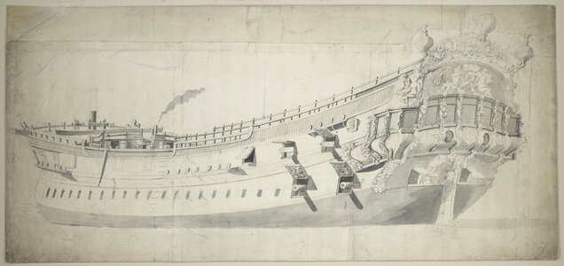
A drawing by Willem van de Velde the Elder (Figure 7) is also frequently used to reconstruct the Sovereign. It is not of the Sovereign as designed or launched. Some believe that it shows the ship as it was during its 1659-1660 repair. (Sephton 2011, 55) It is from later. A reasonable estimate is that was drawn somewhere around 1673. (Fox, Personal Communication) This is evident from the “ramp” that leads from its port entry door. This ramp is first noted at that time as running to the landing stage at the ship's mooring off Gillingham. (Fox, Personal Communication)

The Sovereign may have been moored at Gillingham to facilitate receiving visitors. Thomas Baskerville, who visited the ship here, tells us that “In the river along by Chatham I told 30 stout ships then within the command of the castle of the western side of the river, except the Royal Sovereign[4], which lay at Gillingham, two miles lower.”

The English were still concerned about the 1667 Dutch raid on the river Medway while the Sovereign was here. According to Baskerville, for the Sovereign’s “defence and to examine those that pass up and down the river a little lower, do constantly ride two ships, whose names were the Bramble and Truelove, and these ships are the utmost constant guards on this river.”

Baskerville also tells us how the Sovereign was prepared to receive visitors. “Sixty men are constantly kept in pay to keep her clean, and wait on strangers, here being built for the more commodious going aboard her, a bridge from the bank side to the lowest ebb of the water.” (Baskerville 1893, 277) This is the ramp mentioned above
.

Figure 7 Van de Velde the Elder’s Drawing of the Sovereign of the Seas
1721579235997.png

The van de Velde drawing is not wholly original. Van de Velde superimposed parts of the Payne engraving on his own partial drawing of the Sovereign. (Fox, Personal Communication.) The most obvious clue to this is that van de Velde, like Payne, shows low gratings over the waist and half deck. Van de Velde also shows Payne’s depiction of the head rails and quarter galleries. One explanation for the purpose of van de Velde’s drawing is that he was exploring how these items from the Payne engraving fit with the ship he saw in 1673. They did not. (Fox, Personal Communication) The Sovereign had changed too much by this time for them to do so.

These changes began in 1651, by which time it was clear that Sovereign would benefit from modification. These modifications are described in a 1651 letter to the Commissioners of the Navy from Edward Hall, Peter Pett, William Badiley, Joseph Pett, John Taylor, Richard Badiley, Thomas Rabouet, and Thomas Apkenstal who said:

“wee conceive that to make her more serviceable then now shee is, the gratings and upper decke in the midshipps bee taken downe and the side lored [lowered] to the upper edge of the ports in the midshipps, the upper State Room to bee taken away, the forecastle to be lored to six foote high, and the works abaft to bee taken downe proportionably to the wast [waist] and answerable to the sheere of the worke fore and after, the halfe decke to be shortned as shall bee convenient, as alsoe the head to bee made shorter and soe fitted for the sea. And the galleryes to bee altered as may be comely and most convenient for service.” (cited de Bexer, Callender and Laughton 1928, 62-63)[I have deliberately misspelled the first author's last name. It should not have an "X" in it here, or in any other instance. I have done so because this website's software automatically changes the name to an icon, and I can't figure out how else to stop it.]

Eleven days later the Commissioners of the Navy accepted their proposed changes, noting that:

“if the alterations bee made in her according to the certificate mentioned on the other side, she will bee farr more serviceable both for remote and home employment by reason shee will bee of lesse draught of water by neare a foote then now, and thereby carry her lower tyer of gunns neere a foote higher and without any diminution of her strength or force, or inconvenience in point of state.” (Cited in de Bexer et al. (de Bexer, Callender and Laughton 1928, 62-63)

This Sovereign was substantially different from the original. Among other things, its deck gratings had been removed, as had its topgallant poop (I.e., its “upper State Room”). The forecastle had been also been lowered, the beakhead was shorter, and the long extensions fore of the quarter-galleries had been removed. (Fox, Great Ships 1980, 37)

The Sovereign was again modified in 1659-1660. Exactly what was done at this time is uncertain One change that appears to have occurred was that the Sovereign’s draft was increased to 23 feet, which is 4 feet 4 inches more than its designed draft. That it was allowed to do so hints that other modifications must have taken place because, without them, the gun ports, which were originally five feet from water, would now have been only a few inches from it. These changes seem to have involved re-laying the decks 12 to 18 inches higher. (Fox, Personal Communication \) This does not fully compensate for the increase in draft, so the height of the ports above the lower gun deck may also have been increased, and the deck’s camber may have been reduced. (Fox, Personal Communication). Despite these changes, the gun ports were no longer their original five feet from water. They were now closer; perhaps about 3 ½ feet above it. (Fox, Personal Communication)

Van de Velde had no way of knowing about the changes that had been made to the Sovereign. As a result, the only way he could make the ports fit under Payne’s portrayal of the quarter galleries was to draw them lower than Payne did. (Fox, Personal Communication) This maneuver may be one reason some have erroneously put falls in the Sovereign’s decks (we will further discuss falls when we discuss the decks). Van de Velde’s drawing may have also caused other difficulties in portraying the Sovereign, and these will also be discussed later.

A more accurate portrayal of what the Sovereign may have looked like at this time is given by another drawing van de Velde that van de Velde prepared in 1673 (Figure 8). There are now 12 instead of 13 ports on the middle gun deck. This deck’s aftmost port has been removed because it no longer fits under the quarter galleries. Also, the port next to it, which was formerly shown as arched, now appears as square, and its sill is further above the bottom of the galleries than shown in either the Pett painting or the van de Velde drawing shown in Figure 7. This again attests to the raising of the decks. The gallery’s extensions have also been removed.

Sometime during the Sovereign’s repairs, an additional gun was placed on the upper gun deck (the Sovereign now had 12 gun ports here instead of the original 11). The new port was added where the upper quarter gallery extensions had previously been. Some of the guns on the upper works were also rearraigned. Because of these changes, the Sovereign could deliver a full 50-gun broadside for the first time. (Fox, Great Ships 1980, 37)

Another change was that the large lantern that was originally on the Sovereign had been replaced by one that was smaller, less expensive and, therefore, more expendable. (Fox, Great Ships 1980, 33) This is consistent with this ship’s transition from a tourist attraction to a functional warship

The changes in the 1651 and 1659-1660 repairs transformed the Sovereign from a ship that handled poorly to one that sailed well because of its increased displacement and stability. When Prince Rupert took command of it in 1673, he told the King that "The Sovereign is the best ship you have for riding as well as sailing. (Fox, Personal Communication)

Neither of the van de Velde drawings discussed in this section were used in the present reconstruction.


Figure 8. Van de Velde’s 1673 Drawing of the Sovereign (Starboard Side)
1721579639602.png
Note: Drawing housed at the Royal Museums Greenwich

[1] Sheer plans show the ship from its side.
[2]Peter did not design the Sovereign. His father, Phineas, did.
[3] James Sephton also notes that this painting was the work of Peter Pett, but erroneously says that it is based on the Payne engraving. (Sephton 2011, 56)
[4] The ship’s name was changed from the Sovereign of the Seas to the Royal Sovereign in 1660.

References​

Baskerville, Thomas. 1893. Thomas Baskerville's Journeys in England. Vol. 2, in The Manuscripts of His Grace the Duke of Portland, by Historical Manuscripts Commission, 263-314. London.

de Bexer, E.S, Callender, and L.G. Carr Laughton. 1928. "Documents." The Mariner's Mirror 14 (1): 55-63.

Fox, Frank. 1980. Great Ships. London: Conway Maritime Press.

— "Personal Communication."

— "Personal Communication."

Museum of Fine Arts Boston. ca. 1635. Sovereign of the Seas. Accessed April 10, 2020. https://collections.mfa.org/objects/32448.

Sephton, James. 2011. The Sovereign of the Seas. Stroud: Amberly Publishing.
 

Should We Use Historical Plans?​

This subsection discusses two sets of historical plans for the Sovereign. One is housed in the Royal Museums, Greenwich, London (it is available at https://collections.rmg.co.uk/collections/objects/79839.html#WGQ43mtRY1vxe1X5.99), and the other set is by Sir Robert Seppings.

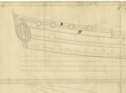
The Royal Museums describe their plans as “Plan showing the body plan with some decoration detail, sheer lines with stern quarter detail and figurehead, and longitudinal half-breadth for Royal Sovereign (1637), a 102-gun First Rate, three-decker. One author has referred to these plans as the “reconstruction draught,” (Sephton 2011, 60) and has recommended it, along with the Payne engraving and van de Velde’s drawing (Figure 7), to “any enthusiast determined on creating a model of this great ship, as she would have appeared in her original form.” (Sephton 2011, pg 68)

Despite what the Museums and the previous author seem to imply, the “reconstruction draught” is not a plan of the Sovereign as it was originally designed or built. They show one less gun port on the lower gun deck than the original, and its ports are irregularly spaced. It also does not show any deadrise (Fox, Personal Communication) (We will discuss deadrising in the next section). The list shown on the plans give the length of its keel as 139 11 ¾ inches, a lower gun deck that is 173 feet long, an extreme beam of 50 feet, and a 20-foot depth in hold. (Sephton 2011, 211) These are not the Sovereign’s dimensions.

The “reconstruction draught” is like the plans drawn in the early 1800’s by Sir Robert Seppings. A listing on his plans gives them the same keel and gun deck length, the same extreme beam, and the same depth in hold as the “reconstruction draught.” Seppings’ plans are so like the “reconstruction draught” that it is reasonable to speculate that the latter may be a preliminary version of Seppings’ plans. It may be no coincidence that the “reconstruction draught” was made in the early 1800’s; which is a little before the time Seppings commissioned a series of models to be built.

The dimensions on Seppings’ plans and “reconstruction draught” are more like (but not identical to) those of the rebuilt version of the Sovereign that was launched in 1701 than they are to the original dimensions. “Rebuilding” is an important term. It is not the same as “repairing.” “Rebuilt” ships were often very different from the original, and often contained just a few timbers from that original. This is exemplified by the rebuilt Tyger (1647). “Only some part of her old keel, stem, and some few of her (frame) frame timbers were made use of in the rebuilding of her.” (Endsor 2020, 76) There was so little of the Tyger left for rebuilding that it prompted one official to say “There is no such thing as His Majesty’s ship Tiger.” (Endsor 2020, 76) This was also true for the Royal Sovereign when it was rebuilt. The rebuilt version used a just few timbers from the wreckage that remained after the original ship burned in 1696. (Fox, Great Ships 1980, 37)

Neither Seppings’ plans nor the “reconstruction draught” were used in the present project.

This completes the discussion of the major data sources that are, and are not used in the present reconstruction. The next section turns to reconstructing the Sovereign’s midship bend.

References​

Endsor, Richard. 2020. The Master Shipwright's Secrets. New York: Osprey Publishing.

Fox, Frank. 1980. Great Ships. London: Conway Maritime Press.

—"Personal Communication."

Sephton, James. 2011. The Sovereign of the Seas. Stroud: Amberly Publishing.
 
And now for a Sir Anthony Deane-like moment of pontification…….

The reconstruction that follows is different from others. One (and not the only) reason is the extensive documentation that is given. This level of documentation has not been previously seen, partly due to the limits imposed by publishers and, in some cases, the way certain authors write. It is also because certain manufacturers of kits for this ship provide no documentation at all, and because many who are interested in this ship tend to prefer pictures to prose.

The result of all these things is that existing plans often to boil down to something not very different from saying “Here are my plans, trust me.” This is ok with a lot of ships, particularly if the author has started with a relatively complete set of historical dimensions. It’s not so ok with the Sovereign because we don’t have complete dimensions for it. As I mentioned in the Introduction, nearly every line on every set of plans for this ship is an assumption. “Assumption” is a delicate word for “guess.” You will no doubt notice that the number of guesses now begins to pile up. Authors of previous plans have not been very good at identifying where they are guessing. I’ll try to make it clear where I’m doing this and, in the process, explain why I made each of the choices I made.

I expect that at least some of you will disagree with some of the dimensions that follow. This is expected because there will always be ambiguity about this ship. However, even more ambiguity will remain if the right questions aren’t asked. I can make a pretty good case that the right questions haven’t been asked about plans for the Sovereign of the Seas. The “right” questions are arrived at by looking at every line on a set of plans, and asking “Why was that line drawn that way?” The posts that follow are attempt to do this. In them, I am attempting to set the bar higher for accepting plans for this ship. Many of the questions we should be asking are identified by each of the topics and subtopics that follow. It’s useful, then, to view the following posts as not only proposing a set of dimensions for the Sovereign, but also as giving many of the questions that should be asked about any set of plans for this ship.
 
Regarding your comments on using historical plans I agree. Studying and building models of English ships built prior to the 1719 Establishment indeed involve a good amount of guesswork in spite of completing a lot of research. One quick example I found was when drafting and building a model of the Charles Galley 1676. The plans from RMG were a good start but when looking at Van de Velde drawings there was a significant difference in the design of the quarter galleries. Normally I would trust the plans but the drawings from VdV are renowned for accuracy and as he did several with the same design of the galleries I modified those found on the plans at RMG. Note that Richard Endsor's painting of the Charles Galley in his book The Master Shipwrights' Secrets also follows the design from VdV, not the plans at RMG.
Loving your posts here!!!
Example of the Charles Galley below.
Allan
Quarter gallery.jpg
Charles Galley Van De Velde 11.jpg
 
Back
Top