-

Win a Free Custom Engraved Brass Coin!!!
As a way to introduce our brass coins to the community, we will raffle off a free coin during the month of August. Follow link ABOVE for instructions for entering.
-

PRE-ORDER SHIPS IN SCALE TODAY!
The beloved Ships in Scale Magazine is back and charting a new course for 2026!
Discover new skills, new techniques, and new inspirations in every issue.
NOTE THAT OUR FIRST ISSUE WILL BE JAN/FEB 2026
- Home
- Forums
- Ships of Scale Build Logs
- Super Detailing Static Models / Other Genres
- Historical Trailways, Guns, Aircraft, and Cars
You are using an out of date browser. It may not display this or other websites correctly.
You should upgrade or use an alternative browser.
You should upgrade or use an alternative browser.
1930 Bentley Blower by Aifix 1/12 build log [COMPLETED BUILD]
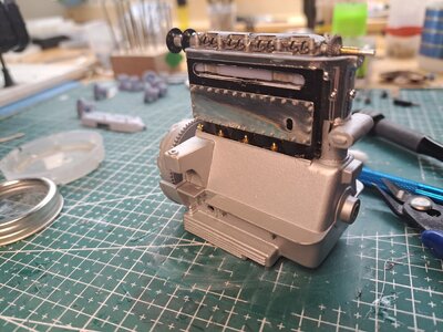
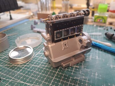
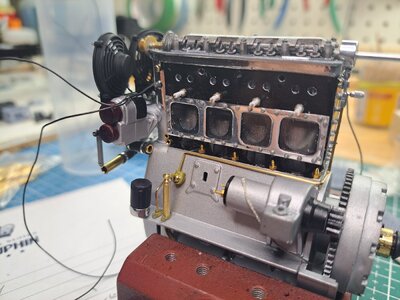
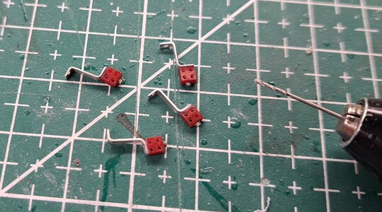
Made the spark plugs and plug wires today. Not sure I like the wire I used. At .5mm dia, the scale is good (about 1/4" scaled up) but it's not as smooth as the ones on my ref car. I'lI look for something else.
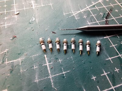
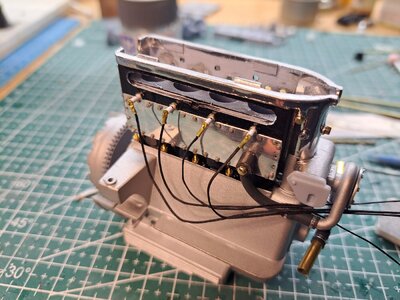
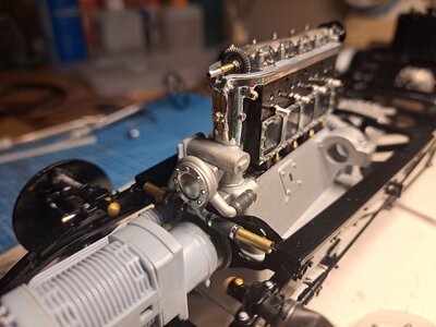
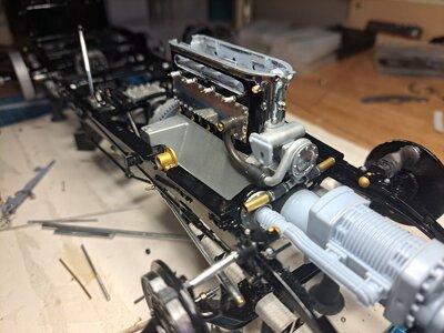
also installed the now finished water pump. Very happy with the result.
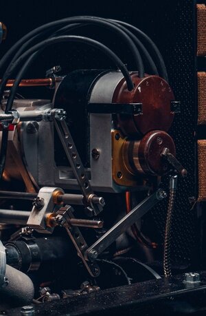
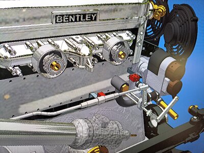
I started 3d modeling the magneto advance/retard ajustement linkage. Should look like this.
I bought some liquid chrome markers. Very impressive !!


also installed the now finished water pump. Very happy with the result.


I started 3d modeling the magneto advance/retard ajustement linkage. Should look like this.

I bought some liquid chrome markers. Very impressive !!
Francois -
I'm continually astounded by the quality of your work and dedication to making an OK kit into something beyond my imagination.
Just a question - wouldn't a car of this vintage have something like 7mm cloth covered wires, even a racing Bentley? My recollection with puttering with '30s cars before I went to hot rods was that this was the norm.
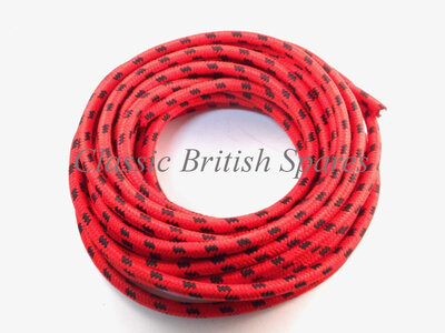

Thank you dave.
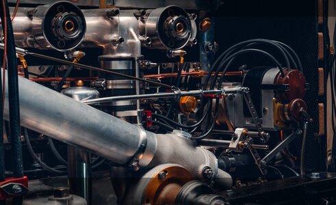
You're probably right about the plug cord but like I mentioned before, I'm reproducing car 'zero' that was built in 2019 and it didn't have that type of cord. The picture I posted yesterday showing the magneto likage and the plug wires in from that car. That being said, it's always good to have you guys 'Sherlocking' my work. Sometimes, it get me away from the tree so I can better see the forest.
You're probably right about the plug cord but like I mentioned before, I'm reproducing car 'zero' that was built in 2019 and it didn't have that type of cord. The picture I posted yesterday showing the magneto likage and the plug wires in from that car. That being said, it's always good to have you guys 'Sherlocking' my work. Sometimes, it get me away from the tree so I can better see the forest.
I know you showed us a few photos of the 2019 version but did't really see spark plug wires. It surprises me that they wouldn't have made those cars period perfect since that repro wire is available with current actual silicone insulation. Oh well. not a big deal or nit pick and for sure not a criticism of Bentley (or your endeavor)Thank you dave.
You're probably right about the plug cord but like I mentioned before, I'm reproducing car 'zero' that was built in 2019 and it didn't have that type of cord. The picture I posted yesterday showing the magneto likage and the plug wires in from that car. That being said, it's always good to have you guys 'Sherlocking' my work. Sometimes, it get me away from the tree so I can better see the forest.
Did some more work on the throttle and magneto linkage. The parts are very small, not sure that they are printable. I would really have liked to be able to adjust the magnetos from the stator control on the steering wheel but I can't find any info on just how it's done. I know that there is a lever of some sort mounted at the end of the steering column but don't know what it looks like.


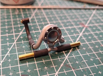
Worked on the blower feed tube today. I removed the moulded features at both ends of the part.
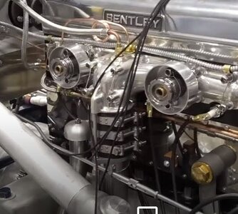
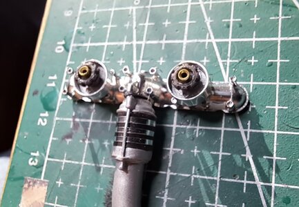
These moulded features represent a rubber coupling with 3 hose clamps and tie rods.
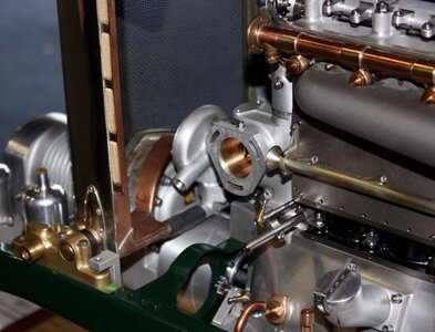
This is the real thing.
And here is mine without the clamps
And once finished
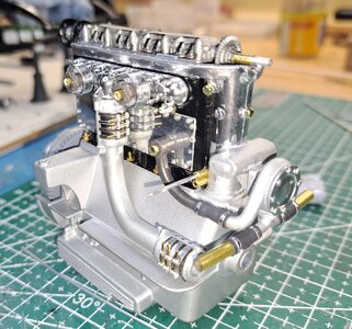
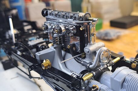
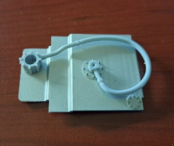
Next. I tackled what seems to be the oil filler neck.
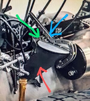
it's this thing. Pointed in red is the filler tube, in blue the cap release lever and in green the cap pivot assy which has a pivot shaft and 2 levers connected to extension springs.
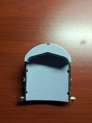
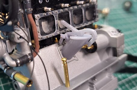
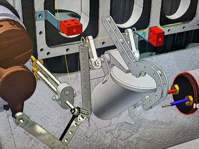
I 3d modeled it the best I could considering the bad picture and lack of info I have. This is what I have.
View attachment 20231028_195245.mp4
I'll print the cap and levers, the rest I'll either modify or
build from scratch.
I also finished modeling the magneto linkage.
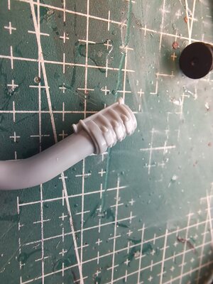
These moulded features represent a rubber coupling with 3 hose clamps and tie rods.
This is the real thing.

And here is mine without the clamps

And once finished


Next. I tackled what seems to be the oil filler neck.
it's this thing. Pointed in red is the filler tube, in blue the cap release lever and in green the cap pivot assy which has a pivot shaft and 2 levers connected to extension springs.

I 3d modeled it the best I could considering the bad picture and lack of info I have. This is what I have.

View attachment 20231028_195245.mp4
I'll print the cap and levers, the rest I'll either modify or
build from scratch.
I also finished modeling the magneto linkage.

Continued on a few more engine details today.
Did the oil level indicator.
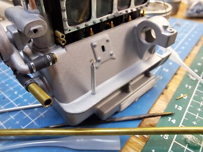
Installed the rev counter with rev cable and tiny cable clamps
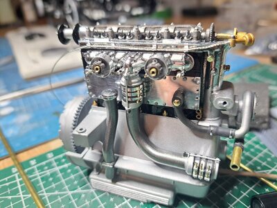
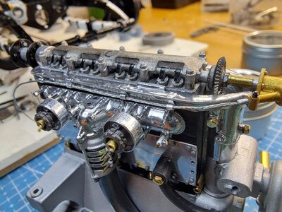
I started to tinker with the water rail, it's this copper tubing.
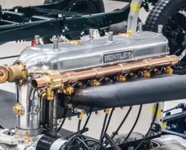
I would like to make it from scratch using a lenght of lead, colored with a copper patina acid and a brass tubing to represent the jonctions. Not sure if it will work but I'll give it a try.
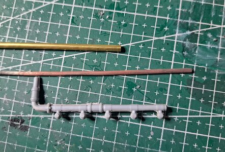
Did the oil level indicator.

Installed the rev counter with rev cable and tiny cable clamps


I started to tinker with the water rail, it's this copper tubing.

I would like to make it from scratch using a lenght of lead, colored with a copper patina acid and a brass tubing to represent the jonctions. Not sure if it will work but I'll give it a try.

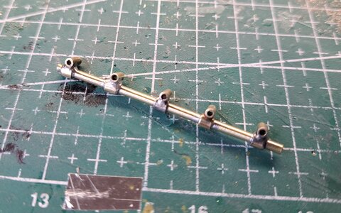
I fabricated the water rail but instead of using a piece of soldering lead colored copper, I used brass tubing, both for the main tube and for the jonction couplings. After cutting all the parts, 11 in all, I tried to glue them together. That did work so good. I decided to solder the joints as on the real thing. So I started by making a welding jig. Which is this.
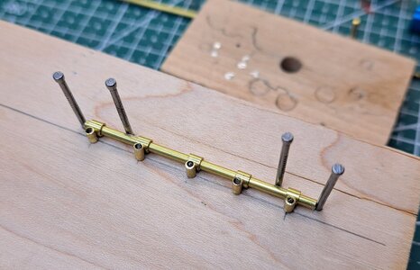
On my first try, I used small steel pins to hold the 5 small vertical tubings but after soldering, the pin were stuck inside the tubes. So that didn't work either. This was the result.

I then replaced the small steel pins with aluminium pin and applied much less solder. This is what came out of the jig.
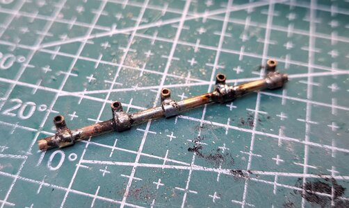
much better. And after cleaning i got this
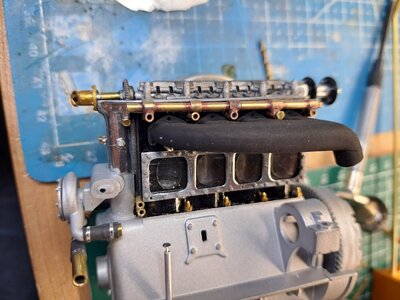
Test fitting to make sure it would fit with the exhaust manifold
and after a quick polishing, got this.
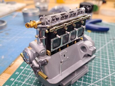
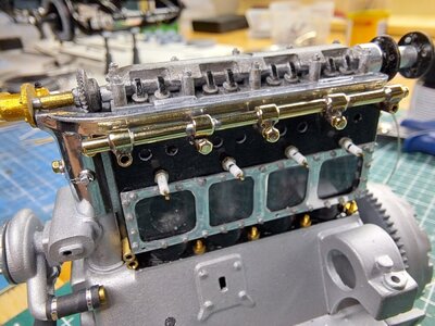
I'm very happy with the result, it came out a lot better than expected. Now I just need to go get a few hex bolt (I'm missing 1 at each end) and to figure out how to make the jonction to the rad.

On my first try, I used small steel pins to hold the 5 small vertical tubings but after soldering, the pin were stuck inside the tubes. So that didn't work either. This was the result.

I then replaced the small steel pins with aluminium pin and applied much less solder. This is what came out of the jig.

much better. And after cleaning i got this

Test fitting to make sure it would fit with the exhaust manifold

and after a quick polishing, got this.


I'm very happy with the result, it came out a lot better than expected. Now I just need to go get a few hex bolt (I'm missing 1 at each end) and to figure out how to make the jonction to the rad.
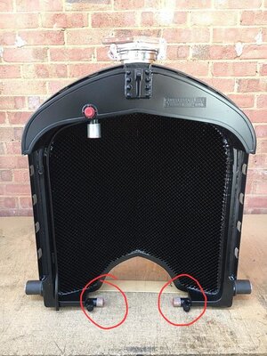
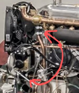
I discovered that on the new old bentley blowers built in 2019, there's a pipe connected to the water rail going down to the water pump. Back in the 30's, this pipe was used only on the non blown car, not on the blowers.
Here's the pipe on one of the 12 new Blowers.
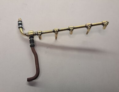
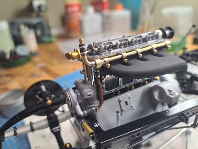
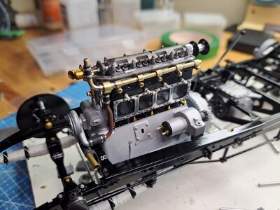
So I added it to the rail setup. I also added the tubing that will connect to the top of the radiator. I also added the starter motor which is actually a micro gearmotor.
Here's the pipe on one of the 12 new Blowers.

So I added it to the rail setup. I also added the tubing that will connect to the top of the radiator. I also added the starter motor which is actually a micro gearmotor.


Thank you Keith.
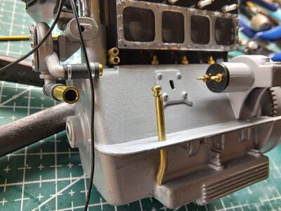
I've been working on the oil management system which is not present in the base kit. Aside from a hose on the underside of the engine, that seems to go from the oil pump to the sump, there's nothing.
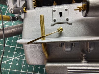
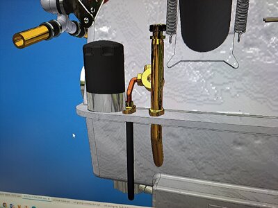
I had already made the oil level dip stick but I didn't like it so i made a new one. I'll also add a modern type oil filter, the oil pump, an oil distribution hub that will connect to the cam shaft among other things. The one part that is in the kit, the hose under the engine, will be modified by replacing the plastic hose by a real rubber hose plus I'll add another hose from the pump hub to the distribution hub.
I also added the cooling fans.
Here are a few pictures.
Only part present in kit
New dip stick
Oil on stick
3d modeled components to be added
Cooling fans in place
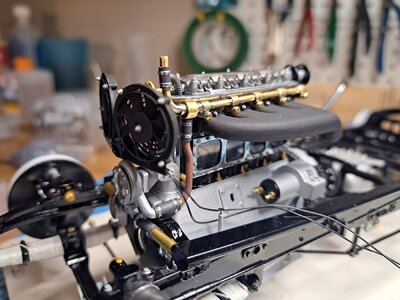
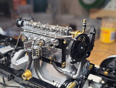
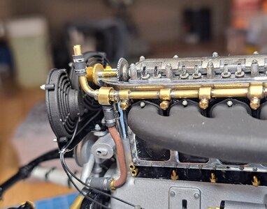
View attachment 20231102_114231.mp4
I've been working on the oil management system which is not present in the base kit. Aside from a hose on the underside of the engine, that seems to go from the oil pump to the sump, there's nothing.
I had already made the oil level dip stick but I didn't like it so i made a new one. I'll also add a modern type oil filter, the oil pump, an oil distribution hub that will connect to the cam shaft among other things. The one part that is in the kit, the hose under the engine, will be modified by replacing the plastic hose by a real rubber hose plus I'll add another hose from the pump hub to the distribution hub.
I also added the cooling fans.
Here are a few pictures.
Only part present in kit

New dip stick

Oil on stick

3d modeled components to be added

Cooling fans in place


View attachment 20231102_114231.mp4
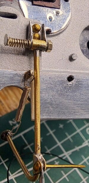
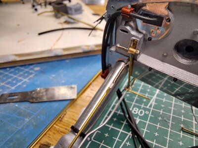
I did the accelarator. It's a welded brass assembly. The pivot incorporate a compression spring as on the real thing. I also started the link rod that goes from the pedal to the carb lever along with the springloaded return rod that goes with it.
Here's what the real thing looks like.
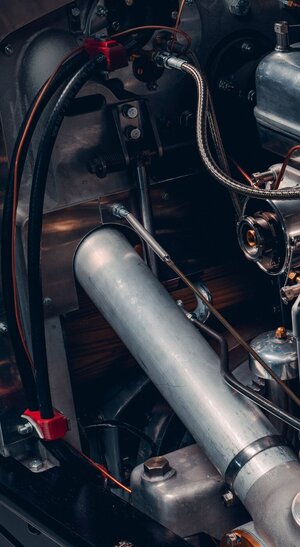
and my version
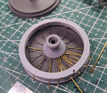
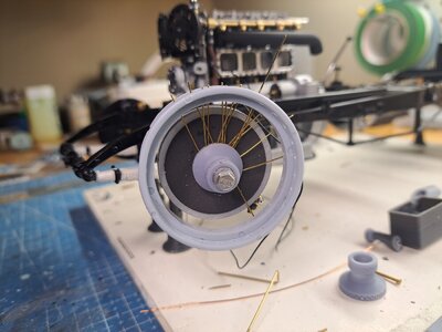
Since I'm waiting for a bunch of resin printed parts, I decided to do a bit of ground work on the wheels. First, I drilled the rims using the drill jigs I designed and printed last summer. They worked great. Then I printed a lasing jig to hold the rim and hub in relation during lasing. And did a bit of test lasing to get the feel of it. It should turn out all right.
Drill jig in use
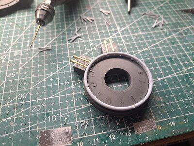
Lasing jig
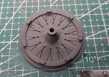
lasing jig in use
test fit on car
Here's what the real thing looks like.

and my version


Since I'm waiting for a bunch of resin printed parts, I decided to do a bit of ground work on the wheels. First, I drilled the rims using the drill jigs I designed and printed last summer. They worked great. Then I printed a lasing jig to hold the rim and hub in relation during lasing. And did a bit of test lasing to get the feel of it. It should turn out all right.
Drill jig in use

Lasing jig

lasing jig in use

test fit on car

The plug wires are done on the passanger side and with the installation of the oil filler tube assy, the oil management system is now complete.
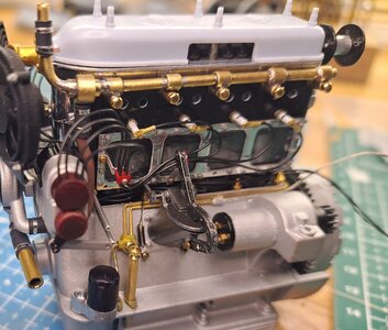
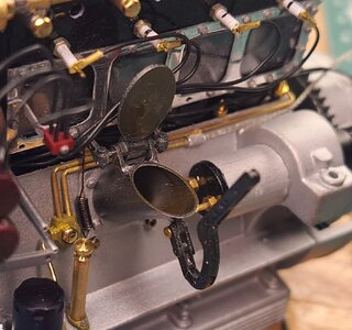
I'll try to complete the magneto linkage next. I really wanted these linkages to work but I'm not sure l'll be able to. In order to respect the scale, the levers are very small ans fragile. They break very easily. The worst case will have them glued in place and for show only.
In other news, I had to redesign the wheel rim drilling jig. When I first modeled the wheels, I copied the lacing pattern of the Alfa romeo wheels but it turns out that the number of holes between a given pair of wires is different so the drilling angle is different. I also had twice too many wires on the inner most part of the wheel. I'll continue the wheel lacing as soon as I finish the engine.
Last edited:
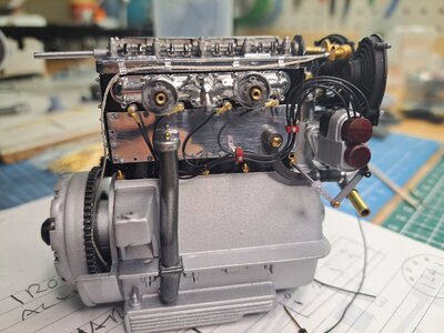
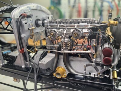
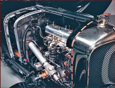
I worked on the magneto linkage and after some tweaking and lever reprinting, I was able to assemble a functional mecanism. Now, it still needs to be connected to the stator shaft on the steering column but that will be much later. Here are a few pictures.
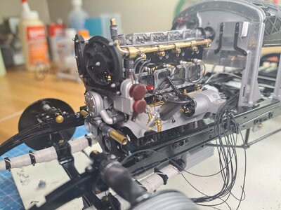
View attachment 20231113_120750.mp4
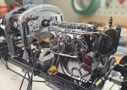


View attachment 20231113_120750.mp4


It’s becoming a impressive engine, François. Looks great.I worked on the magneto linkage and after some tweaking and lever reprinting, I was able to assemble a functional mecanism. Now, it still needs to be connected to the stator shaft on the steering column but that will be much later. Here are a few pictures.
View attachment 406884
View attachment 406881
View attachment 406883
View attachment 406880
View attachment 406885
Regards, Peter
WOW - just WOW
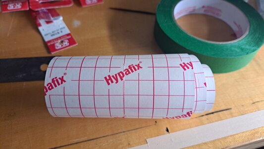
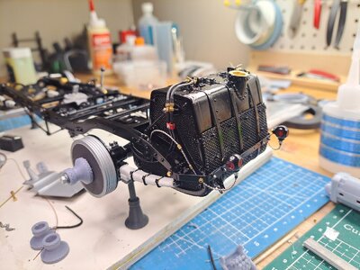
Ok, so I'm just about ready to install the engine on the frame but before I do that, I need to rout the fuel lines from the tank all the way to the front. So I decided to finish the fuel tank install and go from the tank to the fuel pump and to the from. On the real car, the fuel lines are coverded with a cloth tape that I imagine is fire proof. I tried many different type of tape but nothing worked until I remembered a medical tape used on a WW1 plane I did last year. It's called Hypafix, it's seems to ge made of some type of fabric l, is very thin and flexible. It did the trick. This is the tape.
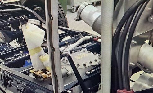
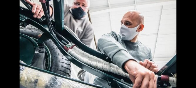
This is what I was aiming for.
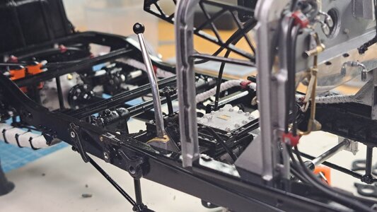
And here what I made.
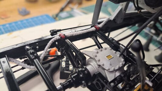
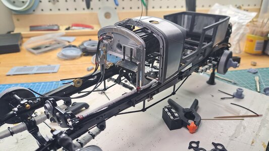
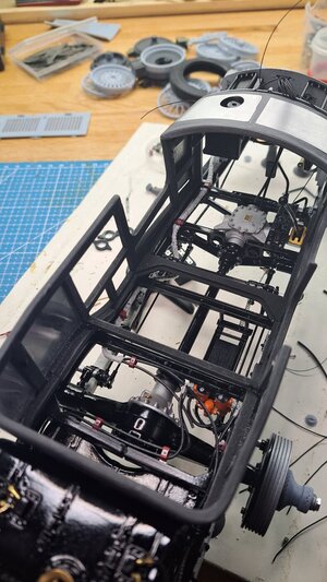
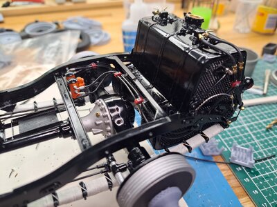

This is what I was aiming for.


And here what I made.


