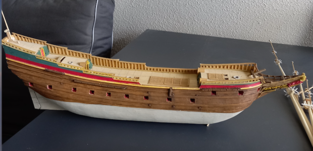
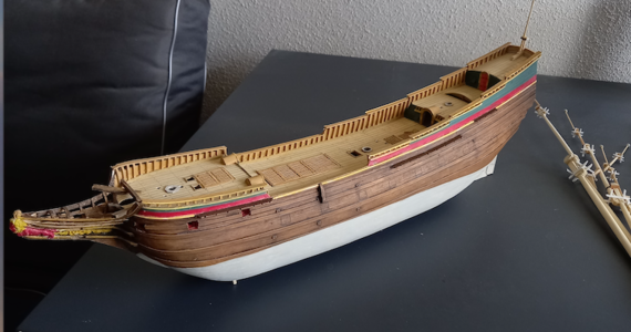
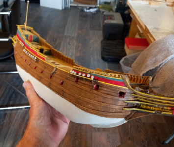
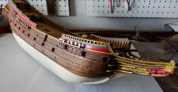
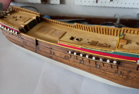
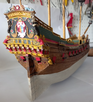
A 17th century Dutch armed trader – scratch built from card [COMPLETED BUILD]

Joined
Mar 20, 2020
Messages
483
Points
373

Location
Alkmaar, Holland
Exactly one month ago I started this model of a 'pinas' of 134 feet long.
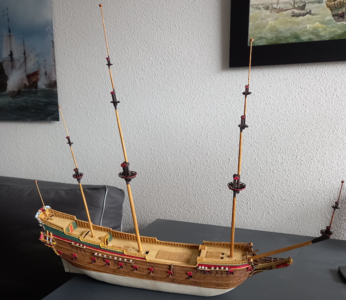
0 pinas 5.png

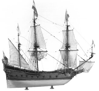
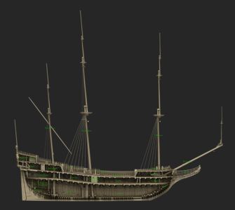
There is a story connected to this ship. I built it five times, the first one starting in 1980, the last one a month ago. It is the ship that is described in all its details by the Amsterdam lord mayor, diplomat, lawyer, cartographer and collector Nicolaes Witsen (1641-1717) in his famous book 'Aeloude en Hedendaegsche Scheepsbouw en Bestier' (Old and Modern Shipbuilding and Managing) from 1671. He was the first in Holland to describe the trade of shipbuilding in Holland and his book still is the most important source for 17th century Dutch maritime matters. His choice for this particular ship of which he wrote down over 40 pages of dimensions of all sorts was not incidental. He deliberately chose a ship of medium size (38 meters was an average length in those days) and with a double function: not only was the ship the main means of transport for people and cargo of its days, it was also a platform for a considerable amount of ordnance (24 guns). Thus Witsen combined the characteristics of both a trader and a man-of-war stating that, provided the reader did understand this construction, he was able to build any ship. That is a significant statement, because therefore this ship of his choice is not just a random vessel, is a key for understanding the system of shipbuilding of the era. The type name 'pinas' has become obsolete and disappeared from our language, but the type itself became an icon of Dutch 17th century shipping, with its gracious lines, tasteful decorations, bellowing sails, flapping flags and intimidating guns.
However, Witsen was not exactly a trained teacher. The reading of his book is a frustrating task, because apart from the fact that he constantly mixes up things which often causes confusion, many ship's parts names have disappeared over the years. No wonder that it took me three years to make working drawings based on his texts and sketches and another three years to build a construction model in pear wood in 1/50 scale, with every part in place, even if covered with planking in a later stage.
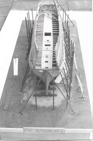
1 Pinas 1.jpg 2 pinas 1.jpeg

The model was purchased by the local shipping museum in my hometown Groningen, so I built a second model for 'use' in my home on a 1/100 scale. This model was sold to a private collector a few years later. Life was expensive with three upgrowing children...
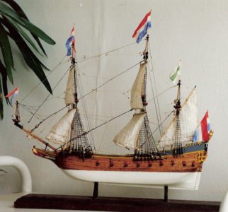
3 pinas 2.png

A presentation in 1988 on a congress for maritime archaeologists about the two different shipbuilding methods described in Witsen's book and by a second Dutch author on the subject, Van Yk, opened the door to a job at the Rijksmuseum in Amsterdam, taking care of the maritime collection there. In the mean time Witsen's re-arranged old text was published in 1994 in the book I wrote about the project, 'Nicolaes Witsens Scheeps-bouw-konst Open Gestelt'. An English translation was published in 2012: 'Nicolaes Witsen and Dutch Shipbuilding in the Golden Age.' Very few people's lives have been influenced in such a total manner by a 17th century patrician and the ship he described.

After my retirement in 2012 I met Rene Hendrickx, my Belgium companion with whom I built the ship for the third time, but this time virtually, in the free downloadable shipbuilding program Delftship. Less than a year ago the program was adapted for public internet use as an educational tool for archaeologists and historians by the company Tijdlab, subsidized by the Dutch Rijksdienst voor Cultureel Erfgoed (Cultural Heritage Agency of the Netherlands). The site is interesting for model builders as well and can be found at: https://witsenscheepsbouw.nl, where also the original drawings for the model can be downloaded for free.
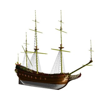
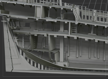
4 pinas 3.JPG 5 pinas 3.png 6 pinas 3.png

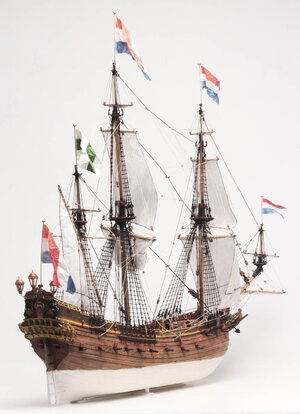
In 2014 I discovered model shipbuilding in card and for its quick results I liked it so much that I decided to build Witsen's pinas in paper and card as an experiment at a 1/77 scale. Earlier this year the model was donated to the Archaeological Museum 'Huis van Hilde' in Castricum, Holland, together with six more models of Dutch traders from the 17th century to illustrate the exhibition of wreck findings that show the large area of Dutch trading contacts of those days.
So again I had to say goodbye to the ship and it did not take long to admit to myself that I missed it dearly.

7 pinas 4.jpg 8 pinas 4.jpg

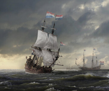
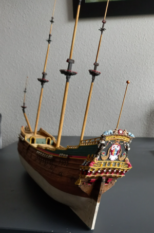
The result was that I started building my fifth pinas model exactly a month ago. The build was a breeze so far. Everything worked out fine. Perhaps you are interested in the process. In the coming time I will show you various stages and the rigging will follow soon, so stay tuned!

Schermafbeelding 2021-08-25 om 14.08.31.png
 
Last edited:
For me it is every time so surprising how fast you can build such a beautiful and detailed card model.

For everybody interested please take a look at the mentioned book written by Ab

Nicolaes Witsen and Shipbuilding in the Dutch Golden Age
by A. J. (AB) Hoving

 
Part two: Preparations.
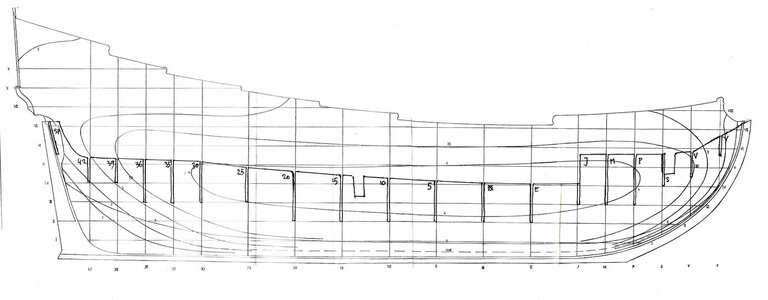
A scratch build always starts with drawings. You need a lines plan, a body plan and a section at the least. It takes some planning to start the build. Let's take a look at the section first.
fig 1.png
Normally I chose the space below the lower deck as the main part of the 'spine' of the model. In this case the forward part of the lower deck however is occupied by the cable tier. This is a closed compartment, so I chose to add it to the spine. That also offers the advantage to get some more material in the bow, which adds to the sturdiness of the model.
Fig 2.jpg
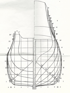
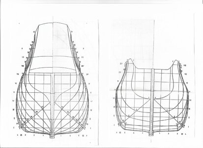
As you see I already drew the slots for the frames. So we turn to the body plan now. Often the plan shows two sides of the ship simultaniously.
Fig 3.PNG
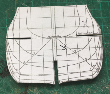
So we have to create two body plans, one for the fore side and one for aft. Anyone who can work with a computer knows that on a Microsoft computer the program Paint can mirror a picture. So if we print them and cut them in the middle we can glue them together to create two complete frame drawings. Take care that the width on the waterline is exactly equal.
Fig 4.jpg
Now the build starts. First the spine was cut. I used three layers of 1mm thick card to get the right size and also added ½ mm strips for the protruding parts of keel, stem and stern. This helps when planking. Slots for the frames are cut and also the holes for the main and fore mast. To support the bowsprit I left the material underneath it in place.
Fig 5.png
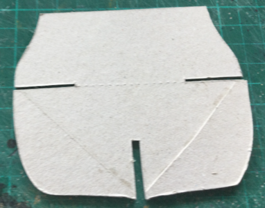
Next I cut the frames. With the printer I produced the right number (8 fore and 11 aft) and glued them on 1 mm card. I also doubled the area where two skin pieces butt. This gives a better landing. Every frame is dry-fitted in the slots of the spine and at the same time the hight of the deck is scribed on the frame. Here I cut the slots for the lower deck and the remaining middle part is perforated to ease the removal of the upper part of the frame in a later stage.
Fig 6.png Fig 7.png
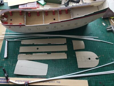
Two strips of sufficient width are fitted into the deck slots, to make the lower deck. I left out the camber of the lower deck, because it is complicated to make and it will not be visible in the model.
Fig 8.png
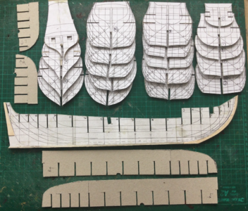
So that leaves us with the basic parts of the model, ready for assembly. This is what you get buying a kit. The difference is that this costs you nothing and it's a lot more exciting (IMHO).
Fig 9.png
Next time I will show you the 'planking' of the model. Stay tuned. If you have any questions or remarks, don't be shy.
 
Last edited:
This is another great and informative posting, Ab. Thank you for sharing the build of the "love of your life" with us!
 
Part two: Preparations.
A scratch build always starts with drawings. You need a lines plan, a body plan and a section at the least. It takes some planning to start the build. Let's take a look at the section first.
View attachment 252711
Normally I chose the space below the lower deck as the main part of the 'spine' of the model. In this case the forward part of the lower deck however is occupied by the cable tier. This is a closed compartment, so I chose to add it to the spine. That also offers the advantage to get some more material in the bow, which adds to the sturdiness of the model.
View attachment 252712
As you see I already drew the slots for the frames. So we turn to the body plan now. Often the plan shows two sides of the ship simultaniously.
View attachment 252713
So we have to create two body plans, one for the fore side and one for aft. Anyone who can work with a computer knows that on a Microsoft computer the program Paint can mirror a picture. So if we print them and cut them in the middle we can glue them together to create two complete frame drawings. Take care that the width on the waterline is exactly equal.
View attachment 252714
Now the build starts. First the spine was cut. I used three layers of 1mm thick card to get the right size and also added ½ mm strips for the protruding parts of keel, stem and stern. This helps when planking. Slots for the frames are cut and also the holes for the main and fore mast. To support the bowsprit I left the material underneath it in place.
View attachment 252715
Next I cut the frames. With the printer I produced the right number (8 fore and 11 aft) and glued them on 1 mm card. I also doubled the area where two skin pieces butt. This gives a better landing. Every frame is dry-fitted in the slots of the spine and at the same time the hight of the deck is scribed on the frame. Here I cut the slots for the lower deck and the remaining middle part is perforated to ease the removal of the upper part of the frame in a later stage.
View attachment 252716 View attachment 252717
Two strips of sufficient width are fitted into the deck slots, to make the lower deck. I left out the camber of the lower deck, because it is complicated to make and it will not be visible in the model.
View attachment 252718
So that leaves us with the basic parts of the model, ready for assembly. This is what you get buying a kit. The difference is that this costs you nothing and it's a lot more exciting (IMHO).
View attachment 252719
Next time I will show you the 'planking' of the model. Stay tuned. If you have any questions or remarks, don't be shy.
 
Fantastisch werk Ab; je bent een genie (Great job Ab; you’re a genius)!
 
Exactly one month ago I started this model of a 'pinas' of 134 feet long.

View attachment 252445

There is a story connected to this ship. I built it five times, the first one starting in 1980, the last one a month ago. It is the ship that is described in all its details by the Amsterdam lord mayor, diplomat, lawyer, cartographer and collector Nicolaes Witsen (1641-1717) in his famous book 'Aeloude en Hedendaegsche Scheepsbouw en Bestier' (Old and Modern Shipbuilding and Managing) from 1671. He was the first in Holland to describe the trade of shipbuilding in Holland and his book still is the most important source for 17th century Dutch maritime matters. His choice for this particular ship of which he wrote down over 40 pages of dimensions of all sorts was not incidental. He deliberately chose a ship of medium size (38 meters was an average length in those days) and with a double function: not only was the ship the main means of transport for people and cargo of its days, it was also a platform for a considerable amount of ordnance (24 guns). Thus Witsen combined the characteristics of both a trader and a man-of-war stating that, provided the reader did understand this construction, he was able to build any ship. That is a significant statement, because therefore this ship of his choice is not just a random vessel, is a key for understanding the system of shipbuilding of the era. The type name 'pinas' has become obsolete and disappeared from our language, but the type itself became an icon of Dutch 17th century shipping, with its gracious lines, tasteful decorations, bellowing sails, flapping flags and intimidating guns.
However, Witsen was not exactly a trained teacher. The reading of his book is a frustrating task, because apart from the fact that he constantly mixes up things which often causes confusion, many ship's parts names have disappeared over the years. No wonder that it took me three years to make working drawings based on his texts and sketches and another three years to build a construction model in pear wood in 1/50 scale, with every part in place, even if covered with planking in a later stage.

View attachment 252446 View attachment 252447

The model was purchased by the local shipping museum in my hometown Groningen, so I built a second model for 'use' in my home on a 1/100 scale. This model was sold to a private collector a few years later. Life was expensive with three upgrowing children...

View attachment 252448

A presentation in 1988 on a congress for maritime archaeologists about the two different shipbuilding methods described in Witsen's book and by a second Dutch author on the subject, Van Yk, opened the door to a job at the Rijksmuseum in Amsterdam, taking care of the maritime collection there. In the mean time Witsen's re-arranged old text was published in 1994 in the book I wrote about the project, 'Nicolaes Witsens Scheeps-bouw-konst Open Gestelt'. An English translation was published in 2012: 'Nicolaes Witsen and Dutch Shipbuilding in the Golden Age.' Very few people's lives have been influenced in such a total manner by a 17th century patrician and the ship he described.

After my retirement in 2012 I met Rene Hendrickx, my Belgium companion with whom I built the ship for the third time, but this time virtually, in the free downloadable shipbuilding program Delftship. Less than a year ago the program was adapted for public internet use as an educational tool for archaeologists and historians by the company Tijdlab, subsidized by the Dutch Rijksdienst voor Cultureel Erfgoed (Cultural Heritage Agency of the Netherlands). The site is interesting for model builders as well and can be found at: https://witsenscheepsbouw.nl, where also the original drawings for the model can be downloaded for free.
View attachment 252449 View attachment 252450 View attachment 252451

In 2014 I discovered model shipbuilding in card and for its quick results I liked it so much that I decided to build Witsen's pinas in paper and card as an experiment at a 1/77 scale. Earlier this year the model was donated to the Archaeological Museum 'Huis van Hilde' in Castricum, Holland, together with six more models of Dutch traders from the 17th century to illustrate the exhibition of wreck findings that show the large area of Dutch trading contacts of those days.
So again I had to say goodbye to the ship and it did not take long to admit to myself that I missed it dearly.
View attachment 252452 View attachment 252453

The result was that I started building my fifth pinas model exactly a month ago. The build was a breeze so far. Everything worked out fine. Perhaps you are interested in the process. In the coming time I will show you various stages and the rigging will follow soon, so stay tuned!
View attachment 252454
Very interesting ship, looking forward to the paper build
 
@Jeanco: 'Great job Ab; you’re a genius'.
No I'm not Jeanco, far from it. I may have some ingenuity though, especially when it's about hiding the mistakes I made in previous phases of the build. Wait and see and you will soon know what I mean.
 
Last edited:
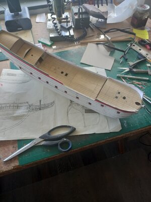
Part 3 Trying to get everything in place.

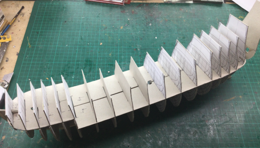
There is a trick while glueing all parts together: both on the frames and on the spine there were several waterlines drawn. I only had to check if they were all lining up. When glueing the deck in, care was taken not to apply any glue to the top of the deck, only to the underside. Once dry the construction appears to be reasonably steady.

For the method how to cover the frames with card I refer to my tutorial here: https://shipsofscale.com/sosforums/...-to-scratch-build-from-card.4676/#post-102230

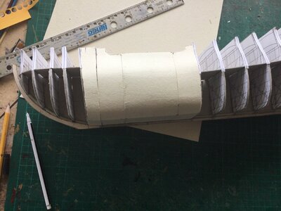
In a relatively large ship like this pinas the area around the main frame does not show much 'movement', so the middle section can be covered with a wide piece of card. Forward and aft it's another story. The frames above deck-level are not doubled, but I glued a strip of thin paper to the edges, to keep them temporarily together once the card will be removed.

pinas 1.JPG

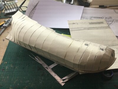
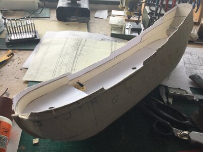
It is important to cut the frames up to their original height, to make sure there is enough material for the top-sides of the hull. In this stage I also draw the deck-line on the outside, by pushing small holes outward with a pin. It helps to get the gun ports at the right height. It takes some testing, trying, cutting and fiddling, but in the end of the afternoon all strips are applied and this is the result:

pinas 2.JPG

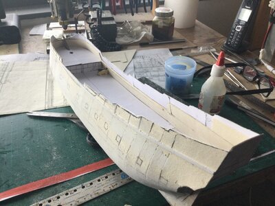
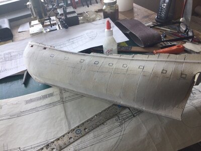
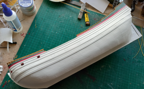
As you can see it's not perfect and I already did some sanding to remove the worse bumps. The material I use for the skin (wood board) easily allows sanding, because it is not laminated. You don't get ugly pieces of fleece hanging down. It just gets a bit rough, but some waterproof sandpaper (applied dryly) takes away the rubbish. Next filler is applied to fill up any dents. It looks worse than it is, of course depending of the accurateness of the cut frames. I only sanded the lower half of the hull up to now, because the upper part has to stand a terrible treatment first:

pinas 3.JPG


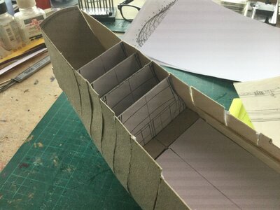
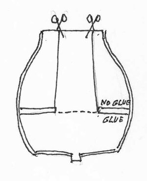
Starting from the main frame the upper parts of the frames are broken down. They were not glued, apart from the sides and the middle part was perforated. It works great to cut the frame from the topside to the extremities of the perforated part (see my sketch). The middle part can be removerd easily, while the two side parts can be carefully released from the ship's sides by carefully rotating them. When some parts are removed the inside above deck level can be doubled by pieces of 1 mm card. Care has to be taken that the original shape of the hull stays unchanged. Therefore I first connect the parts with short pieces of card and once the whole inside is done I add the last layer, a long piece cut to fit the ship's side. Now the upper half of the hull can be treated with filler and sanded as well.

pinas 4.JPG
pinas 3a.jpg
The bulwarks above the upper deck I only double with stiff paper (160 grams), because I want to keep them as thin as possible. I do that because I want to experiment with the inside of the bulwarks. In men-of-war these bulwarks are covered with a ceiling, showing a nice closed ship's side. On merchantmen however people opted for a cheaper solution, using only one ceiling plank on top of the waterways, covered with a covering board. The result is, that the toptimbers remain visible and that's what I wanted to achieve for this model.

pinas 5.JPG

Once the inside is treated, still taking care to preserve the shape, the decks are covered with paper to hide the ugly remains of the torn-off upper frame parts. As you can see I made a test-gun to check wether the height of the gunports is correct. I decided to make a difference between left and right. On the starboard side I will make the gunports open, on the larboardside they will be closed. The tops of the bulwarks are still in a rough stage.

pinas 6.JPG

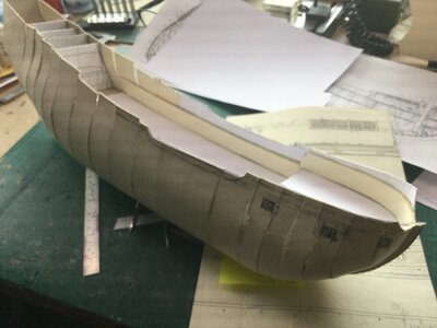
In this stage it is very helpful to give the upper hull some support by means of the sheer strake. It is absolutely essential that this part is glued at the correct location. Mistakes made here will be impossible to correct in a later stage. It takes a lot of measuring (up from the keel) to get this right. Once put into place the top works can be brought to their desired height.

pinas 7.JPG

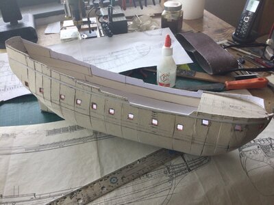
This is the right moment to locate the gunports (open or closed). As you can see the height of the deck is drawn to the hull, as is the line of the lower wale. Sanding and filling is almost done.

pinas 8.JPG

Time to make some missing parts: the upper deck, the quarter deck, the poop and of course the rudder with its helm. Because the upper deck is curved, both longitudinal and with its camber, I made it from three strips of card, supported by several beams. It only shows four deck-beams here, but you have to believe me, there were at least eight of them. Nice moment to check if the shape is still OK. In this process the hull tends to become too wide on the top, so some pressure at the right places is necessary. Al gun ports are cut, all gun-carriages are placed, the gunbarrels will come in later. I tried a trick for keeping the bowsprit in place, but still regret this ugly solution, although nothing of it will be visible in the end.

pinas 9.JPG

Before the decks are glued in I cover them with 160 grams white paper and paint them with Humbrol 93, touched up with a little bit of white. After drying I use a fine-liner to imitate the planking.

pinas 10.jpg

On the outside the wales are glued. I use polystirene strips for them, as for the sheer strake. Taking the sheer strake as a reference it is not too difficult to give the wales their right location.

pinas 11.jpg

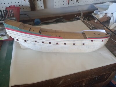
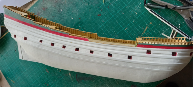
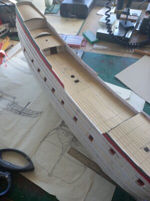
So here is the completed (but not yet finished) hull before planking. The upperworks have been covered with painted strips of paper to imitate the clinker topsides.

pinas 12.jpg

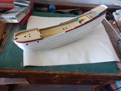
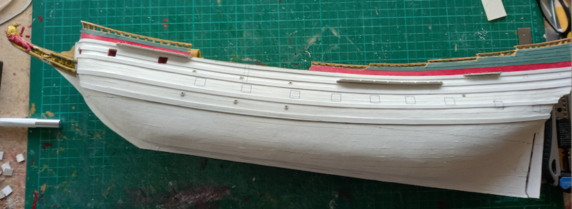
And here is the model planked with plastic strips (see my tutorial for details) and work on the inside of the bulwarks are started the way I planned. Next time more about finishing the hull.

pinas 13.jpg
 
Lovely work again Ab.
What suprized me of Witsens model is the 45 deg angled stem, fore mast fwd on the stem and long beakhead of his ship.
This as you see the trend in the 2nd half of the 17th century that the stem angle becomes more steap and the beakhead shorter and steaper.

Is it purely the shape of the hull, a more sleak faster hull that is forcing to this construction? Is Witsen using an older ship as example? Or are the merchant ship builders lagging behind with the navy ship builders?
 
Thank you Maarten,
It is hard to say in what year the ship was built from which Witsen took the measurements. I guess not too long before the writing of the book, which came out in 1671. In ship design there is a big difference between men-of-war and traders from around 1650 onwards. Before that time the two did not differ too much. Even in 1652 officials from the Zealand admiralty came to Zaandam to buy ready-made hulls to turn them into warships because of the outbreak of the first Anglo-Dutch War. Apparently the shape of the hull was less important. Around that time admiral Maarten Tromp insisted on special ship design for warships, with flatter decks. The trend to build straighter stems was probably partly caused by the lack of sufficient curved trees. That a longer keel worked out fine for sailing qualities was just a bonus. But this is all guesswork of course. There are no sources dealing with the subject.
What is even more striking is the difference in beam between my Akerboom (1681) and this pinas. The former having a length-breadth ratio of almost 3.7 to 1, the pinas 4.6 to 1. Different purposes, different shapes.
 
Ab, thx for the info.
BTW for your Akerboom design did you also use Witsens proportions and maybe contemporary "bestekken" in combination with Van de Velde drawings to create the hull shape for Akerboom?

It would be very interesting to see how you can build a model of a particular ship from such a limited amount of data.

I am familiar with your book of Witsen which is a great source of info, and also the way that GC Dik used for the 7 provincien.

Sorry for being of topic but the way to arrise a specific ship from the death is hugely interesting. For instance for the future I am thinking of a model from the "Jaarsveld" of which Van de Velde made a stern and bow drawing in detail.
 
Part 4. Finishing the hull

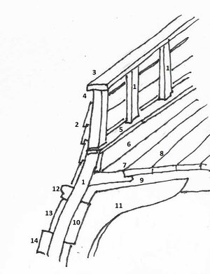
First I have to explain how I executed the bulwarks on this ship. As I stated before, the inside of merchantmen's bulwark was mostly not planked. Only one ceiling planks was placed, covered by a covering board in which slots for the top timbers were made. On the outside the top plank was omitted, which resulted in a narrow balustrade with the tops of the top timbers acting as the vertical parts. To imitate this I glued a strip of thick card into the corner of deck and bulwark and placed short top timbers on top, just protruding above the ship's sides. A railing was glued on top.

1 constructie.jpg
1: top timber
2: top planking
3: cap rail
4: omitted strake
5: covering board
6: ceiling plank
7: waterway
8: deck plank
9: deck beam
10: deck clamp
11: knee
12: sheer rail
13: outside plank
14: wale
a.png

The last picture of my latest post showed the hull 'planked' with self-adhesive plastic strips. It is a quick and rewarding process, but before painting priming is required, for normal paint will not hold on plastic. The closed gunports were cut in the plastic layer and in the cut some dark ink was rubbed. This proces was repeated with every new layer of paint. As you can see the hull is fairly smooth as a result of filling and sanding.
b.png

Now the waterline can be drawn, which is important for the next step: painting. But first the beakhead, the channels and the rudder were made. I always make my beakheads seperately and as soon as the scrolwork is inserted and the cheeks are tightly in place, the whole construction is glued to the stem. Of course the lion is made from Magic Sculpt, as is the scroll work ('kam' (comb) in Dutch). The railings and the grating deck are mounted little later, after the first layer of paint.
The channels are made of 1 mm card, with slots for the dead-eyes. Once they are mounted with their chain plates the amount of stress that can be applied to the shrouds is remarkable.
The rudder is still in dry fit, waiting for the hinges, which can only be mounted after the painting of the 'dry' part of the hull.
c.png

After the bulkheads have been placed the first layer of paint is applied. It always needs a second layer. During drying of the paint several small items are made like gratings, scuppers, the clamp for the tack, the railings of the beak head and the cat-heads, together with several more details on the beak head like pin-rails and deck. Now the hinges of the rudder can be glued on, which hold the rudder tightly in place. Because they are just paper, the connection between hull and rudder is enforced with some metal pins.
d.png

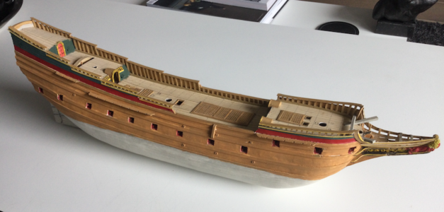
How dull the paint looks, ever after two layers of paint, is illustrated here. But here comes the magic. Once completely dried, all the brown parts are treated with a layer of Van Dyk's Brown, immediately wiped off with a soft cloth. The result is always surprising:
e.png f.png

The wood-like result can be seen here:
g.png h.png

We are really approaching the time consuming detailing of the ship. But first the paint has to dry thoroughly. During that time I constructed the masts to prevent me from getting bored. I'm an impatient man. Fortunately there are always lots of little things that have to be done, so waiting is not really necessary.
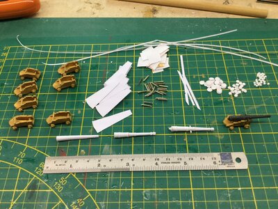
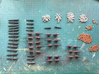
Deadeyes and guns with the gunport lids are made in this stage. I always leave my deadeyes in a light color as long as the shrouds are not mounted because of my fading eye-sight. Once all is in place I will darken them. Dead-eyes are treated with in my tutorial.
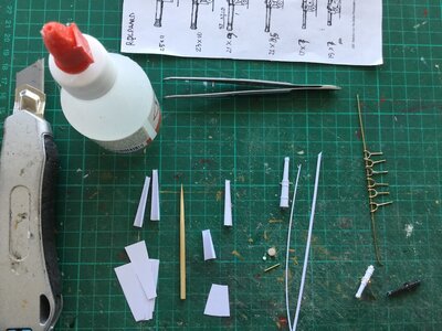
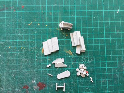
The making of the gun barrels can be seen here:
i.jpg j.jpeg k.JPG afb 5.jpg

In this model there are iron guns, which I paint black and treat with graphite afterwards, and bronze ones, which I paint bronze, fouled with green paint while the bronze is not entirely dry. The closed gun ports get their hinges and the outside planking gets bolts, imitated by small black paper circles made with a punch.
l.png

Finally the stern is decorated with a mixture of paper and Magic Sculpt. I use the Witsen family crest, as he pictured it himself in his book. On the sides I portrayed him and his wife. I'm not much of a sculptor, I place quantities of material in the right locations, the rest is bluff, suggestion only.
m.png

A lot of preparations for the rigging have been done, but that's a subject for the next time. I'm six weeks on my way now in this build and everything seems to work out reasonably fine so far.
 
Last edited:
Back
Top