
Hi Paul convinced you can.Just wonderful Maarten! Thank you for taking us on the journey with you. You made us almost feel like we could do it too!

-

SUBSCRIBE TO SHIPS IN SCALE TODAY!
The beloved Ships in Scale Magazine is back and charting a new course for 2026!
Discover new skills, new techniques, and new inspirations in every issue.
NOTE THAT OUR NEXT ISSUE WILL BE July/August 2026 -

Win a Free Custom Engraved Brass Coin!!!
As a way to introduce our brass coins to the community, we will raffle off a free coin during the month of August. Follow link ABOVE for instructions for entering.
You are using an out of date browser. It may not display this or other websites correctly.
You should upgrade or use an alternative browser.
You should upgrade or use an alternative browser.
A Dutch Fluyt in shell first, reconstructing the "Ghost ship" scale 1:36
- Thread starter Maarten
- Start date
- Watchers 77
-
- Tags
- dutch fluit
Hi Jim,Please do bother us with photos of the second one (if this is not too much ask) I love those become live step by step. Will you add diluted bitumen Juda to visualise\deepen the dimples?
Sorry man he will be covered in oil paint in the near future. This model will get a life like appearence. The hull wil be in bitumen. The statues painted in colour.
@Peter Voogt @Pathfinder65 @shota70 @Uwek @Steef66 @Dean62 @Herman
Many thanks for your likes, comments and help.
Hope for the onces who don t carve yet it can help them to start for themselves.
Very relaxing and fun to do. And you can even take it on holiday or a bussiness trip")
Many thanks for your likes, comments and help.
Hope for the onces who don t carve yet it can help them to start for themselves.
Very relaxing and fun to do. And you can even take it on holiday or a bussiness trip
- Joined
- Oct 15, 2017
- Messages
- 1,204
- Points
- 443

Maarten, I'm catching up on some of my favorite builds. Wonderful progress you've made on your ship. I agree with Uwek, you could stop right where you are and present your project as a diorama of a shipyard build! You certainly have shown us all some of your hidden carving talents as your Hoekman element turned out great. I do appreciate you presenting him in the stylistic flavor of the times.
Really well done.
Really well done.
Good afternoon Maarten. Bravo. What a wonderful log about your carving of the Hoekman. Brilliantly executed Maarten. Cheers GrantThe first Hoekman is finished except for some brushing and buffing which I will do at home.
The second layer of hair is added and I fine tuned his body to give him more waist. His shoulders are lower and his chest is reduced. The lower and upper consoles will be cut when he is fitted on the ship.
The statue is all cut with chisels except for a slot between his legs and the top of his head which were done with a rotary bit.
See below.
View attachment 390548
View attachment 390543View attachment 390544View attachment 390545View attachment 390546View attachment 390547
I won t bother you with cutting the second one")
Thx gents again for comments and likes.
And although work on the second hoekman is going on in the background I am back in my workshop and continue with the hull.
After a lot of the hull design tutorials of @Waldemar I decided to do a little fine tuning on my main frame design and came up with the following design in blue compared to the prevous in black.

If I project this on a 3D sonar scan of the wreck it perfectly fits.

And below in blue comparing with the ralamb fluyt which seems to have far less tumble home then the ghost ship but is of a slightly later period.

The new main frame design now allows me to continue with the first floor and bilge frame to continue on the 3 bilge planks of the ship.
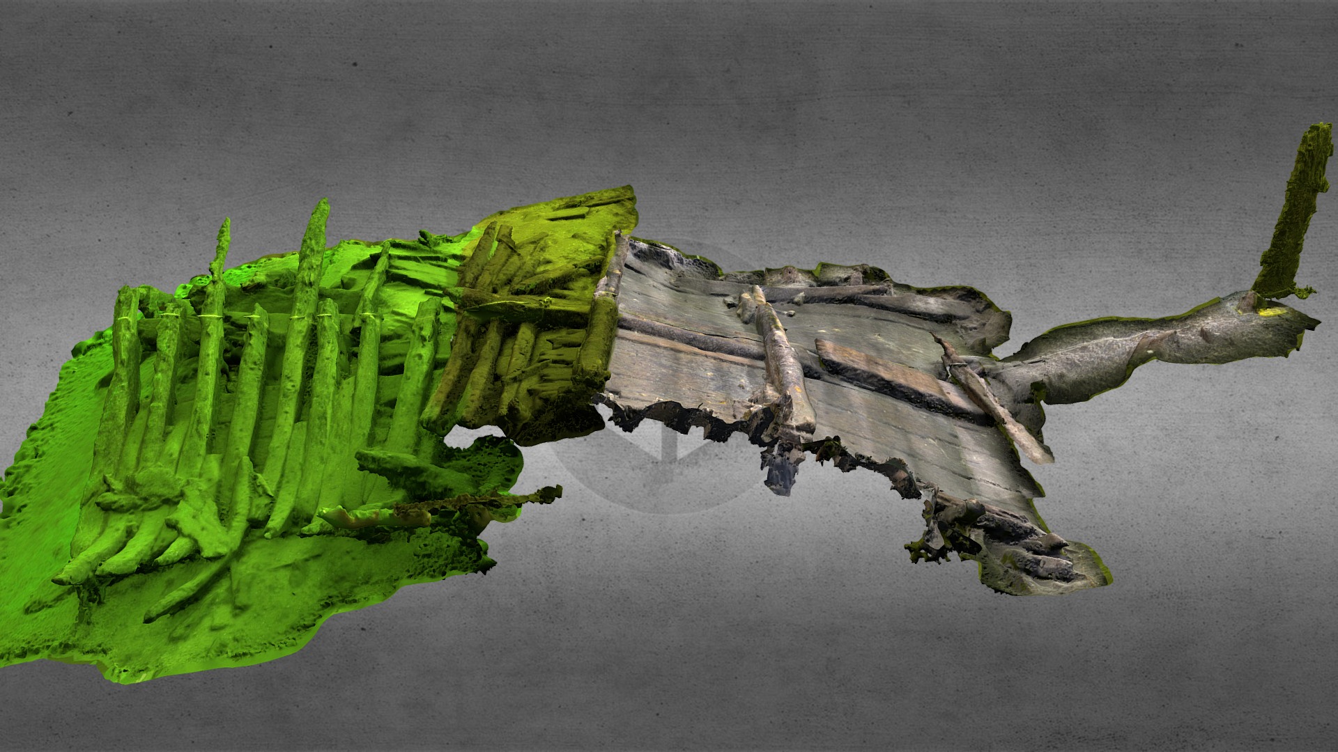
I also found data of a new wreck in Dutch waters which is mentioned as a straatsvaarder, which means a ship sailing to the mediterranean typpically a fluyt.
This ship seems to have a complete flat bottom.
 sketchfab.com
So I will keep the flat bottom for my hull.
And although work on the second hoekman is going on in the background I am back in my workshop and continue with the hull.
After a lot of the hull design tutorials of @Waldemar I decided to do a little fine tuning on my main frame design and came up with the following design in blue compared to the prevous in black.
If I project this on a 3D sonar scan of the wreck it perfectly fits.
And below in blue comparing with the ralamb fluyt which seems to have far less tumble home then the ghost ship but is of a slightly later period.
The new main frame design now allows me to continue with the first floor and bilge frame to continue on the 3 bilge planks of the ship.
I also found data of a new wreck in Dutch waters which is mentioned as a straatsvaarder, which means a ship sailing to the mediterranean typpically a fluyt.
This ship seems to have a complete flat bottom.
Oostvoornse Meer 8 (OVM 8), Netherlands - 3D model by waterduvel
South of the port of Rotterdam lies a lake which used to be the river outlet of the Brielse Maas. This was the main shipping lane to the port of Rotterdam from the 13th until the 18th century. In 2014, the Dutch Cultural Heritage Agency (RCE), conducted an archaeological assessment of the OVM 8...
sketchfab.com
So I will keep the flat bottom for my hull.
Last edited:
- Joined
- Sep 3, 2021
- Messages
- 5,210
- Points
- 738

Hello Maarten,Thx gents again for comments and likes.
And although work on the second hoekman is going on in the background I am back in my workshop and continue with the hull.
After a lot of the hull design tutorials of @Waldemar I decided to do a little fine tuning on my main frame design and came up with the following design in blue compared to the prevous in black.
View attachment 392203
If I project this on a 3D sonar scan of the wreck it perfectly fits.
View attachment 392204
And below in blue comparing with the ralamb fluyt which seems to have far less tumble home then the ghost ship but is of a slightly later period.
View attachment 392202
The new main frame design now allows me to continue with the first floor and bilge frame to continue on the 3 bilge planks of the ship.
I also found data of a new wreck in Dutch waters which is mentioned as a straatsvaarder, which means a ship sailing to the mediterranean typpically a fluyt.
This ship seems to have a complete flat bottom.
Oostvoornse Meer 8 (OVM 8), Netherlands - 3D model by waterduvel
South of the port of Rotterdam lies a lake which used to be the river outlet of the Brielse Maas. This was the main shipping lane to the port of Rotterdam from the 13th until the 18th century. In 2014, the Dutch Cultural Heritage Agency (RCE), conducted an archaeological assessment of the OVM 8...
So I will keep the flat bottom for my hull.
Two questions, based on your sketches:
1) Will you corner the sharp edge between the hold's plane and the R=1/4W?
2) How will you configure the hold's plane and the rebate in the keel? I've seen examples where the garboards are angled to meet the rebate in the keel:

.
Thanks, Maarten. It's very pleasing to see some practical application from all the effort so far...
.
- Joined
- Oct 23, 2018
- Messages
- 987
- Points
- 403

Really interesting thread and I hope to see you and your model in 4 weeks in Amsterdam.
Last edited:
.
By the way: 'Waldemar' is another user with apparently the same real name. My nickname is "- Waldemar -" because nicknames cannot repeat themselves and I had to choose something else.
.
Yes, the sharp edge is a common part of the design of a lot off shell first hulls. I want to experiment with this so put it into my design. I think it will also help me to close the first bilge plank around the bow. We will see.Hello Maarten,
Two questions, based on your sketches:
1) Will you corner the sharp edge between the hold's plane and the R=1/4W?
2) How will you configure the hold's plane and the rebate in the keel? I've seen examples where the garboards are angled to meet the rebate in the keel:
View attachment 392211
My garboard stroke is already angled creating space for the pumps, but I don t draw this as it is not controlled by the frames but by the rabbet.
Last edited:
- Joined
- Sep 3, 2021
- Messages
- 5,210
- Points
- 738
Yes, the sharp edge is a common part of the design of a lot off shell first hulls. I want to experiment with this so put it into my design. I think it will also help me to close the first bilge plank around the bow. We will see.
My garboard stroke is already angled creating space for the pumps, but I don t draw this as it is not controlled by the frames but by the rabbet.
 , thanks for your reply.
In the mean time, I'm still curious about the frame radii you used, as I came across another discussion on this particular topic, but I'm having difficulty tracing back what and where. To be continued
I am curious which discussion you found, most probably Waldemar s. The radii used are not fixed by rules. I used the radii which fitted my design which came from the wreck drawings except for the lower hull which is sunken into the sea bed.
In the mean time, I'm still curious about the frame radii you used, as I came across another discussion on this particular topic, but I'm having difficulty tracing back what and where. To be continued
For this I used the ratios as mentioned by Witsen for the floor and bilge, these points are crossed by this pair of radii. Secondly I have choosen radii which have plain fractures of the vessels width, as there was no decimal system in the 17th century.
Most probably these radii were the shipwrights experience and craftmanship.
- Joined
- Sep 3, 2021
- Messages
- 5,210
- Points
- 738
If I recall correctly it was Hoving comparing Witsen's publication with the publication of a French author. It might take me a while; there's so much (conflicting) information floating about...I am curious which discussion you found, most probably Waldemar s. The radii used are not fixed by rules. I used the radii which fitted my design which came from the wreck drawings except for the lower hull which is sunken into the sea bed.
For this I used the ratios as mentioned by Witsen for the floor and bilge, these points are crossed by this pair of radii. Secondly I have choosen radii which have plain fractures of the vessels width, as there was no decimal system in the 17th century.
Most probably these radii were the shipwrights experience and craftmanship.
Haha, most probably because the reality is just unknown.If I recall correctly it was Hoving comparing Witsen's publication with the publication of a French author. It might take me a while; there's so much (conflicting) information floating about...
After fine tuning the center frame the floor and bilge frame part are prepared.

These are the only frame members joined together, all other frame members will only be fitted to the planking. Fitting with two treenails each of 1,5 Amsterdamse duim.

Marking the center.

And fit it at 1/3 of the ships length.


Next step is fitting the first bilge planks around the bow.
These are the only frame members joined together, all other frame members will only be fitted to the planking. Fitting with two treenails each of 1,5 Amsterdamse duim.
Marking the center.
And fit it at 1/3 of the ships length.
Next step is fitting the first bilge planks around the bow.
- Joined
- Dec 9, 2019
- Messages
- 1,012
- Points
- 443
Witaj
Oglądam twoją relację z ogromną przyjemnością jest to coś nowego dla mnie czekam na więcej . Pozdrawiam Mirek
Hello
I watch your report with great pleasure, it's something new for me, I'm waiting for more. Regards, Mirek
Oglądam twoją relację z ogromną przyjemnością jest to coś nowego dla mnie czekam na więcej . Pozdrawiam Mirek
Hello
I watch your report with great pleasure, it's something new for me, I'm waiting for more. Regards, Mirek
Last edited by a moderator:
