A Dutch Fluyt in shell first, reconstructing the "Ghost ship" scale 1:36

.​

Hello Maarten,

You are already at an advanced stage and I would like to show you something that is unlikely to be found anywhere else. You decide for yourself if and how you will use it.

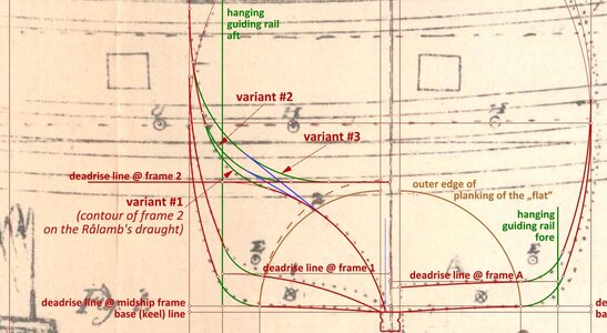
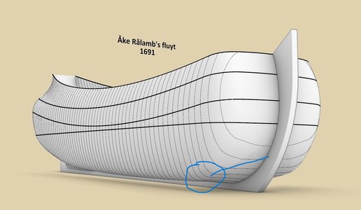
The last leading frame is special in a geometrical sense (ie. of usually different construction than all the rest of the leading frames), and was variously drawn by the designers of the period. This most probably has mainly to do with the choice of better waterflow to the rudder or – alternatively – better capacity, and maybe also to get easier surfaces to shape in the shipyard in this spot. I have drawn three possible variants, however, these too do not show all possibilities.

Variant #1 (as drawn by Rålamb): bilge sweep radius = 2 x normal radius; tangent to the 'flat',
Variant #2: bilge sweep radius = 2 x normal radius; tangent to the deadrise height at this location,
Variant #3: bilge sweep radius = 3 x normal radius; tangent to the deadrise height at this location.

In the last two variants, the 'flat' is connected to the bilge sweep by the line (in blue), tangentially to both these curves.


ViewCapture20230904_141914.jpg

.​
 
Last edited:
.​

Hello Maarten,

You are already at an advanced stage and I would like to show you something that is unlikely to be found anywhere else. You decide for yourself if and how you will use it.

The last leading frame is special in a geometrical sense (ie. of usually different construction than all the rest of the leading frames), and was variously drawn by the designers of the period. This most probably has mainly to do with the choice of better waterflow to the rudder or – alternatively – better capacity, and maybe also to get easier surfaces to shape in the shipyard in this spot. I have drawn three possible variants, however, these too do not show all possibilities.

Variant #1 (as drawn by Rålamb): bilge sweep radius = 2 x normal radius; tangent to the 'flat',
Variant #2: bilge sweep radius = 2 x normal radius; tangent to the deadrise height at this location,
Variant #3: bilge sweep radius = 3 x normal radius; tangent to the deadrise height at this location.

In the last two variants, the 'flat' is connected to the bilge sweep by the line (in blue), tangentially to both these curves.


View attachment 392784

.​
Hi Waldemar,

Many thanks for your addition.
In the stern I go from vertical installed planks in line with the keel to angled planks which meet the stern at a 90 deg angle and the wale at +/- 45 deg. This shape in the flute stretches the plank to its maximum abillities and is guiding my shape towards the scheerstrook. I will prepare a template with the above info if this is feasible in my current hull design.
 
Next is the bow and its first bilge plank.
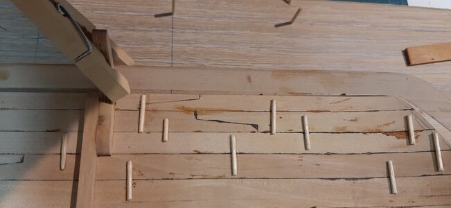
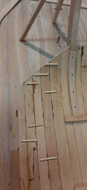
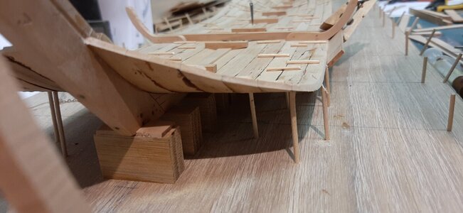
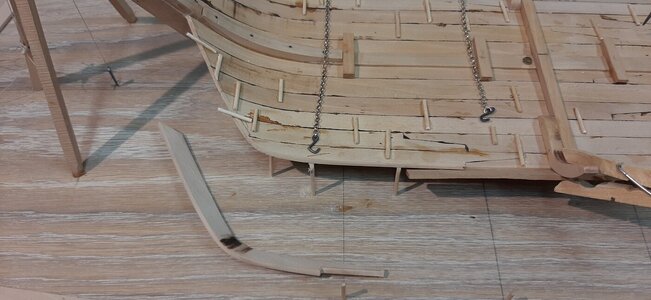
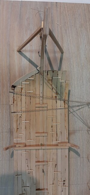
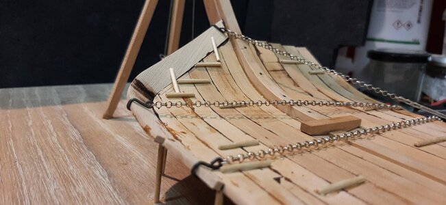
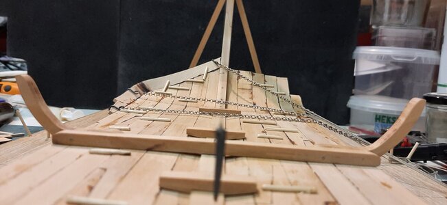
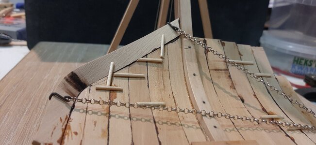
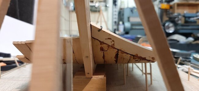
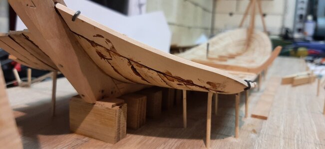
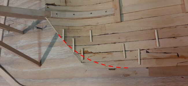
To shape the bow I have cut off the planking at an angle of some 45 deg.
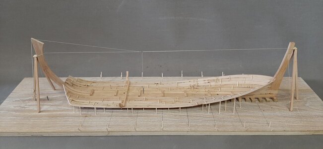
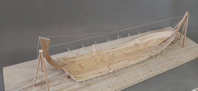
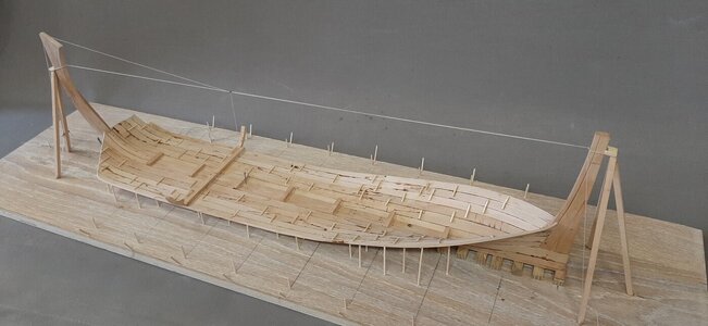
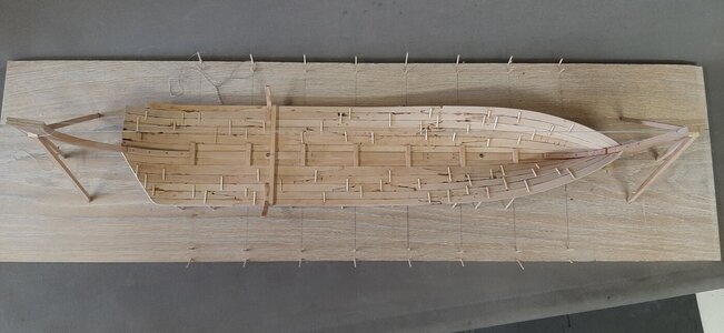
An overview at the start of this major change of the hull shape
20230904_090833.jpg
20230904_090859.jpg
20230904_090920.jpg
20230904_090942.jpg

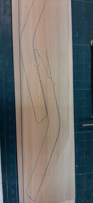
After cutting of the bow section I copied the shape of the plank needed by making a paper mould. This is used to copy the shape to a board.
The grain should run as much as possible in the length of the plank through the bend, otherwise it will brake during the bending process.
20230904_193033.jpg

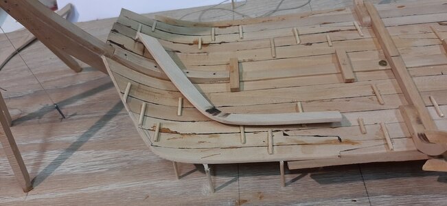
The shape of the plank before and after bending on a heat plate and soldering iron, compared to the bow.
20230904_194623.jpg
20230904_202217.jpg

Now the shape is roughly created in the plank it is time to fine tune the hull. First towards the fwd side it needs to be slightly tapered as you can see when holding a straight plank along its side.
20230904_195617.jpg

It is a process of fitting and filing until it properly fits with all its bends and angles.
20230904_202619.jpg
20230904_202631.jpg

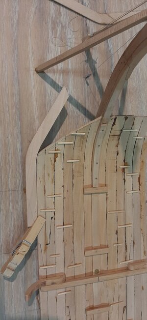
Next I fit two strips holding the plank in place after fitting it, in reality with nails, in my model with a drop of CA.
20230904_203212.jpg

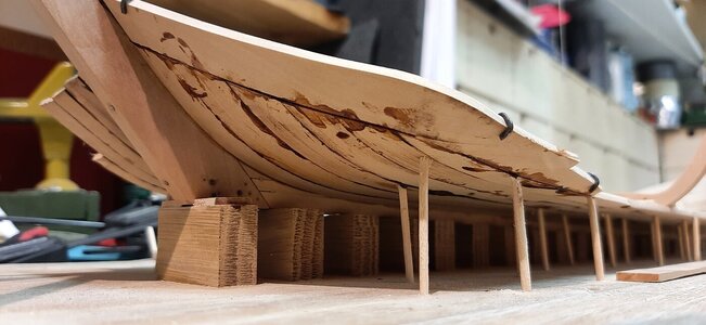
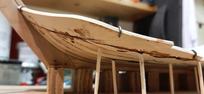
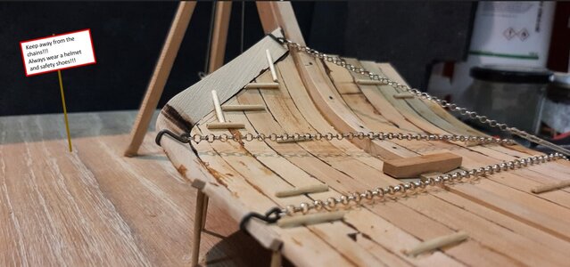
I glue the plank in place with my brown PVA to directly simulate caulking. The hel (chains) keep the plank in place while the temporary clamps were fixed with nails. The brown spots of PVA will be easily sanded away when the hull is released from its dock.
20230904_205355.jpg
20230904_205242.jpg
20230904_205218.jpg
20230904_205132.jpg

I enjoy that you now really see the blund hull shape emerging from the flat floor planking.
20230904_205010.jpg
20230904_205021.jpg
20230904_205036.jpg
20230904_205043.jpg

Next time the SB side hopefully creating a symetrical hull.
 
Next is the bow and its first bilge plank.
To shape the bow I have cut off the planking at an angle of some 45 deg.
An overview at the start of this major change of the hull shape
View attachment 392856
View attachment 392857
View attachment 392858
View attachment 392859

After cutting of the bow section I copied the shape of the plank needed by making a paper mould. This is used to copy the shape to a board.
The grain should run as much as possible in the length of the plank through the bend, otherwise it will brake during the bending process.
View attachment 392860

The shape of the plank before and after bending on a heat plate and soldering iron, compared to the bow.
View attachment 392876
View attachment 392877

Now the shape is roughly created in the plank it is time to fine tune the hull. First towards the fwd side it needs to be slightly tapered as you can see when holding a straight plank along its side.
View attachment 392862

It is a process of fitting and filing until it properly fits with all its bends and angles.
View attachment 392863
View attachment 392864

Next I fit two strips holding the plank in place after fitting it, in reality with nails, in my model with a drop of CA.
View attachment 392865

I glue the plank in place with my brown PVA to directly simulate caulking. The hel (chains) keep the plank in place while the temporary clamps were fixed with nails. The brown spots of PVA will be easily sanded away when the hull is released from its dock.
View attachment 392873
View attachment 392872
View attachment 392871
View attachment 392870

I enjoy that you now really see the blund hull shape emerging from the flat floor planking.
View attachment 392866
View attachment 392867
View attachment 392868
View attachment 392869

Next time the SB side hopefully creating a symetrical hull.
Very beautiful photos explain this phase of the planking of the bow, Maarten. And the hel does a hell of a great job.
Regards, Peter
 
Last edited:
Thx gent for your comments.

Hi Waldemar,

Unfortunately all the fluyt wrecks sofar are with their bottom in the sand so we can't check.
I do agree with you that your shape is easier for the first plank, but I want to test this shape and sofar it is perfectly feasible. Sawing planks in specific shapes was definately done, we see this for instance on the wreck of Batavia for some of the stern planks.
Actually higher in the ship the shape like this is easy to form as the planks in the side are quickly tilting around the bilge and then just bend inwards. Higher in the hull we see this in the wrecks of Anna Maria, Ghost ship and the Tallinn wreck.

I expect the +/- 45 deg angled shape of the planks meeting the bow is done just to create a shape as boxy as possible, otherwise they could have just used planks running from stern to stem which is easier in construction and most probably stronger. In all the above mentioned fluyt wrecks we see this construction of angled planks at bow and stern. For a wood carrier like this it provides more space and length in the side of the hull creating a more economical hull which was a very important feature for Dutch ship building.
We will see, maybe I will hit a wall in the near future, but sofar so good and otherwise a lesson learned :) .
 
Very interesting to follow along Maarten. How wonderful it is to have Waldemar around looking over your shoulder and making such insightful and valuable suggestions. This is model shipbuilding at its highest level.
 
.​

Thanks, Maarten. I understand that you have already made your final decision, so creating a time-consuming post with all the explanatory graphics, photographs or arguments probably won't change it anymore. All the more reason for me to be curious about the results of this experiment. At most, I will limit myself to encouraging comments such as "This is model shipbuilding at its highest level". :)

.​
 
At most, I will limit myself to encouraging comments such as "This is model shipbuilding at its highest level". :)
Indeed. Seeing that I do not have the knowledge to partake constructively in the discussion, I am limited to making "encouraging comments". My lack of ability does not preclude me though from recognizing model building at its "highest level"! ;)
 
.​

Thanks, Maarten. I understand that you have already made your final decision, so creating a time-consuming post with all the explanatory graphics, photographs or arguments probably won't change it anymore. All the more reason for me to be curious about the results of this experiment. At most, I will limit myself to encouraging comments such as "This is model shipbuilding at its highest level". :)

.​
Hi Waldemar,

Oh no please give your comments, much appreciated, they are most welcome and of added value to me. The more people will give comment and advise the better the outcome will be. Yes I do like to experiment to see what is possible and what not and see what the bounderies are, so maybe I will go flat out and have to restart my boxy shape to something less extreme further in the build.

In Ralambs fluyt it seems to be largely comparable with the radius of the bilge until the fwd part of the stem and the vertical lines parallel which means that there is no narrowing at the bottom unless the scheerstrook narrows which is not the case at that point yet. However the triangular shape seems to end higher at the stem.
ViewCapture20230808_004400.jpg
 
.​

Admittedly, I'm now looking intensively at 17th-century Dutch warship designs of more complex shapes than fluits, boyers, galliots or even Witsen's pinas (all of relatively simple design concepts featuring individual frame sections of fixed radii), but if you give me some time I'll put together something potentially useful. I'm sure Ab Hoving's extensive experience in this matter will be very enlightening here if he wishes to comment.

.​
 
Last edited:
Maarten, aside from the excellent workmanship I find your build highly educational. I am no Maritime historian and my research seldom goes beyond what models I make, but the Dutch approach to planking layout really is new to me.

Everything defies the planking principles which are more commonplace.

Just as a side note, what is the "Safe working load" of your miniature chain pullers? ROTFROTF
 
.​

Hello again,

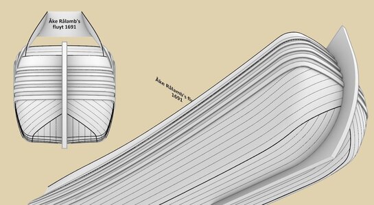
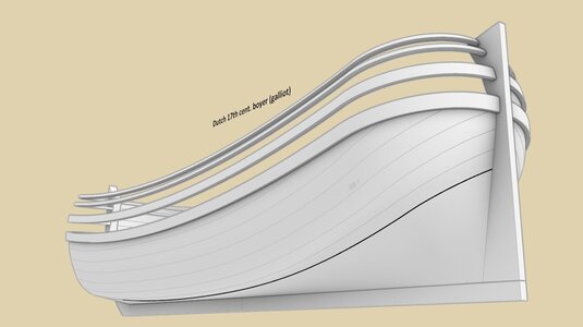
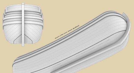
I assume that this is the effect, as below, that you intend to get, more or less. I have prepared two samples, based on Rålamb's fluit and boyer, both sporting very full, boxy hull. This is a bit of a simplification (all planking boards are of equal width and there are no optional stealers), but the hopes are that for illustrative purposes these should be sufficient.

Note that the outer edge of the 'flat' has a smooth, gentle shape in these samples, without a sharp kink as you have done in your model. Despite of that, or perhaps more correctly – thanks to such a shape, the planking boards terminate at about a 45-degree angle on the stem or the wale, exactly as you supposedly plan to do. But it's best that you judge these shapes and the correlation of these lines yourself.
ViewCapture20230906_070032.jpg


ViewCapture20230906_083541.jpg


ViewCapture20230906_083843.jpg


In my opinion, the sharp kink of the "flat" edge is not only unnecessary, but may be actually self-destructive of the effect you intend to achieve. Because somewhat paradoxically, if it goes particularly wrong, it might even force you to lay the planking boards parallel to the wale at the bow (which you don't want, as I understand it). Not to mention the unnatural shapes, which will cause a lot of trouble in execution and will not look convincing at all.

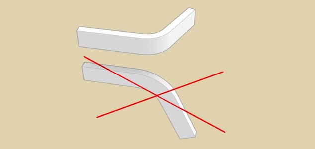
It's true that at the stern of the Batavia 1628 some very short boards were laid, cut in an 'L' shape. But that's not quite the right comparison, because in this particular case these short 'L' planks connect the hull sides to the flat surface of the square-tuck stern, and the builders’ aim here was purely to cover the cross sections of the wood (normally exposed in square-tucked ships intended for European waters only), in order to make it immune to the particularly destructive elements in the tropics (quite successfully, as can be judged from the wreck). And, as can be expected, this 'bend/cut' is not in a plane parallel to the planking, but in a perpendicular plane, as below.
ViewCapture20230906_090050.jpg


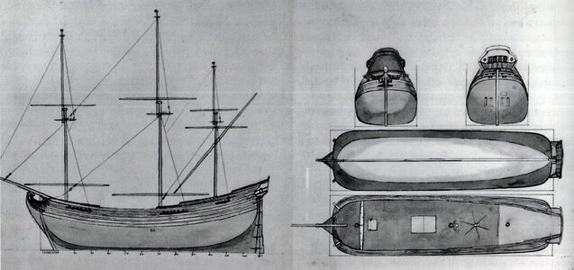
I agree that archaeological finds of large vessels such as fluits are not particularly helpful when it comes to this aspect. Yet a quasi-technical drawing by Adam Silo from „your” period has survived, which shows a sample shape of the outer edge of the „flat” in a classical fluit (white plane). The smooth, rounded contours at the bow area may be clearly seen in the view from below.

Fluita - Adam Silo ok. 1700.jpg


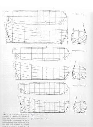
Ab Hoving's reconstruction drawings of the VOC 1697 ships, based on precise co-ordinates from the VOC Resolutie of this year, as well as period iconography (which you may know better than me, by the way), do not suggest such sharp kinks of the „flat” at the bow, quite the opposite.

voc1.jpg


Uff, really, there was so much work to do preparing this comment that next time I think I'll already take an example from more sympathetic users than me and, instead of suggesting something, I'll just limit myself to an encouraging nod. Anyway, you have been warned and now the decision is yours, as is the „responsibility” for the results. :)

.​
 
Hi Waldemar,

Much appreciated for the efforts you put into this and these look really convincing.
I have already discussed with Ab also and he agrees with you on the sharp angle but is also very interested in the outcome if I continue, just as a test.

Personally I feel you both have a valid point and the angle should just be a little less as you show above.

I think as a matter of test I just add some test planks to see how the shape evolves if I continue, after that I will remove them and prefer the shape you proposed.
If I don't do the test we will never know what the outcome will be. I have already tested with the next strake and this already hasd a very slight curve.

This build is party an experiment but the outcome should give a convincing hull shape.

Many thanks for your help and input.
 
G'day Maarten, I've just spent a glorious couple of hours catching up with your build, absolutely amazing, I kept looking for the little men that are building her, impressive and immaculate thinking and workmanship,
best regards John,
 
Maarten, aside from the excellent workmanship I find your build highly educational. I am no Maritime historian and my research seldom goes beyond what models I make, but the Dutch approach to planking layout really is new to me.

Everything defies the planking principles which are more commonplace.

Just as a side note, what is the "Safe working load" of your miniature chain pullers? ROTFROTF
Hi Nigel,

I think you missed the sign on the yard.
Schermafbeelding 2023-09-06 162733.jpg
 
G'day Maarten, I've just spent a glorious couple of hours catching up with your build, absolutely amazing, I kept looking for the little men that are building her, impressive and immaculate thinking and workmanship,
best regards John,
Thx John.
 
Back
Top