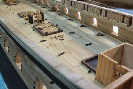
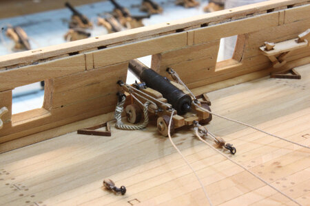
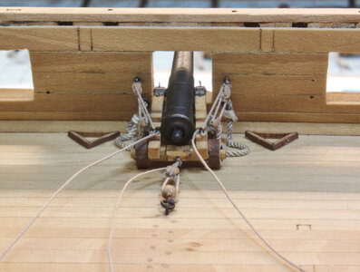
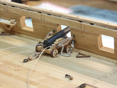
I am now rigging the Cannon Haul Pulleys using 3mm Single Blocks and .3mm Rope from Dry Dock Model and Parts


 |
As a way to introduce our brass coins to the community, we will raffle off a free coin during the month of August. Follow link ABOVE for instructions for entering. |
 |
 |
The beloved Ships in Scale Magazine is back and charting a new course for 2026! Discover new skills, new techniques, and new inspirations in every issue. NOTE THAT OUR FIRST ISSUE WILL BE JAN/FEB 2026 |
 |


Dear DonnieSo, I thought I would attempt to show my method step-by-step of how I am doing this (from the last post). I am not endorsing this as this is the way to do this, as we all know there are many ways to rig things, but this is the only way I found for this application. What are these for? The eye bolts will attach to the Bulwarks. The pulley already has the haul line attached. The tweezers are mounted in a vise.
So, here we go. I am using two sizes of line, .3mm and .4mm and a 3mm block pear.


Looks very nice and neatThank you all again.
Latest:
I will have to cheat - the coils will have to be made separately and positioned accordingly and the end of the "terminated" lines. The method I have used in the past is not working well at this time.
View attachment 355518
View attachment 355519
View attachment 355520
View attachment 355521
Hi Donnie,I think my end results are fairly close enough, but I should have been more careful !!!
Note: it is a good idea to put together one port frame first and then see if the measurements are correct. However, in my defense, I want to say this: CAD Drawings for ships are in 2D and just can not take into consideration CURVES. So, when the drawing is transferred to the CNC machine, this is where things get off - BUT, I could be wrong - don't take my word for it - just be mindful of the parts.
Yes,
This means that I got a little ahead of myself. Again, not being careful - a little aggravated at me -- However, in going back to measure the ports, I am off by about .5 to .6 mm in height (port height a little too tall) while some are almost dead on as far as the height of the port. All of the widths are very good and right on. So, these images show one particular example. Whew - I guess not too bad for taking the kit pieces at face value and not measuring them. But again, who knows.
So, this means that according to the kit, all of the C and D parts should have had a little (about .5mm) removed from the heights. However, your experience might differ from mine. Overall, I am not going to worry much about .5mm
The Camera angle makes the gun port (top right image) looks warped. Not sure how that happened, but that camera shot is not good.
View attachment 300595

Hi Bob. It is great to see you back here!Hi Donnie,
I wish I had seen your build log before I cut my gunports out. I trusted the template drawings to be correct since there's no mention otherwise in the English instruction book. Now all of my gunports are framed and planked over. I thought it was weird that the sill parts didn't fit the openings, and the thought never occurred to me that the templates were showing the finished opening size, so I cut my sill parts down to fit the opening. Too late now to fix it. The only solution I can come up with is to cut them to the proper size which would remove the sill parts completely. That would expose the end grain of the frames at least on the bottom. I could paint the sills red like seen on most ships anyway but then I'd have to paint the inner bulwarks red as well. It's a dilemma.
My biggest concern now is whether the cannons are going to fit the openings when I get the deck installed and planked. I guess time will tell on that one, but I'm hoping they will.
I'm finding your build log to be very helpful on things I haven't yet done. I'm far behind you in my construction, fortunately for me. I did the steps up to the upper planking on one side of the model, then put the model aside for some time. I've just now gotten back into it. I guess I could fix the gunports on the unplanked side which would require making the sills from scratch, but I'm not sure how I'd fix the already planked side. That's one I'm gonna have to think about before I move on.
Take care,
Bob Hunt
Glad to be back Heinrich. I'll be checking in daily from now on.Hi Bob. It is great to see you back here!
