-

Win a Free Custom Engraved Brass Coin!!!
As a way to introduce our brass coins to the community, we will raffle off a free coin during the month of August. Follow link ABOVE for instructions for entering.
-

PRE-ORDER SHIPS IN SCALE TODAY!
The beloved Ships in Scale Magazine is back and charting a new course for 2026!
Discover new skills, new techniques, and new inspirations in every issue.
NOTE THAT OUR FIRST ISSUE WILL BE JAN/FEB 2026
You are using an out of date browser. It may not display this or other websites correctly.
You should upgrade or use an alternative browser.
You should upgrade or use an alternative browser.
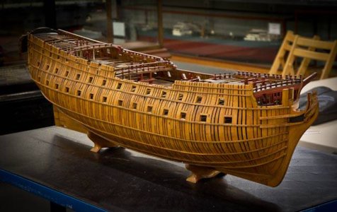
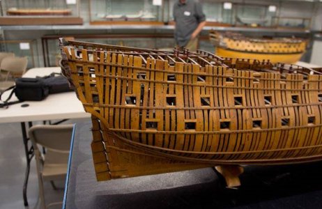
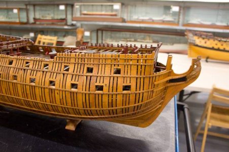
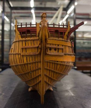
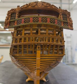
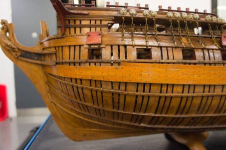
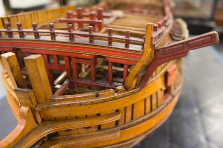
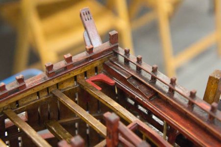
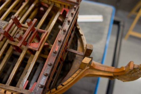
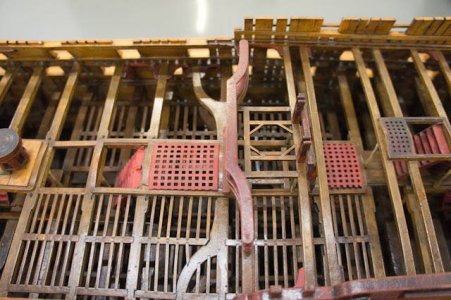
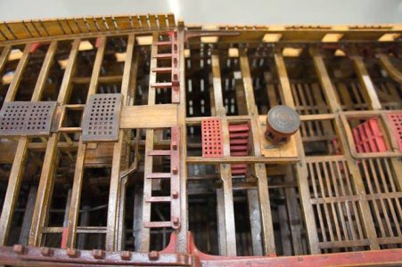
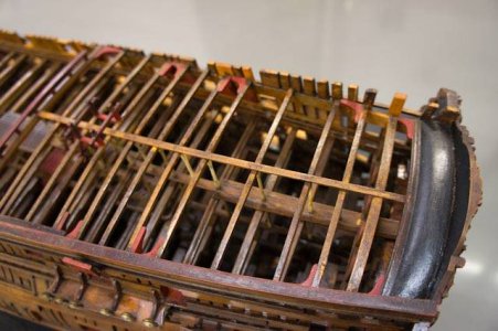
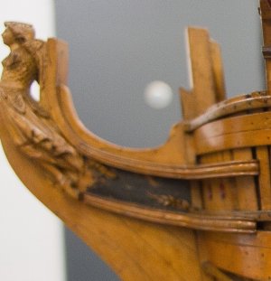
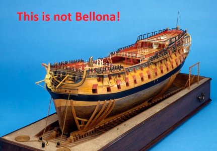
Dear Warren, When working with the plans, do not use the photographs of the "copper-plated" model presented by Sir Charles Middleton to King George III. The fact is that this model represents a different class of ship, most similar to the Dublin class (also a Slade design), but does not match the plans of the Bellona class at all.

Funny timing. I just finished the download, one page at a time. I will spend the next few days studying it (the contract). You mentioned Elephant, She is a sister ship to Bellona. Do you have a contract for Elephant?
Iutar. Thank you. I have seen many photographs of that mode. You have several that are new to me and also answer one of the questions that came up while gathering details of the stem, stern and keel
warren
warren
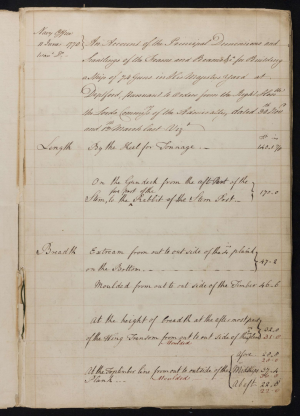
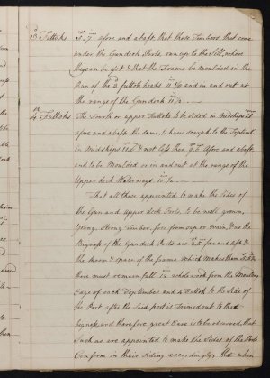
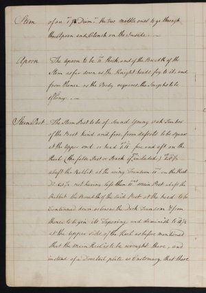
Attached is a transcribed copy in pdf. Keep in mind Elephant was twenty years after Bellona so may not be applicable for some things. There is a contract for a 74 gun written in 1770 that may be more appropriate. https://www.rmg.co.uk/collections/objects/rmgc-object-531385 I have not yet transcribed it but the hand writing is pretty clear. Sample pages below. There are a number of high resolution drawings of masts and yards for 74s on the Wiki Commons site that you may find helpful if you are going to rig her. NB: They are from about 1778 and 1780 so may be different for Bellona. Two examples follow:Do you have a contract for Elephant?
Allan
1778

1779

Attachments
Thank you allen. I downloaded the contract for Culloden yesterday. SJ Sone is using it as a reference for his build of Bellona. I have downloaded your transcribed contract and will compare it to the notes I made yesterday. I intend to import and scale the keel/stem/stern drawing I have and measure the major timbers. This will be a turning point for me as I feel like I finally have something to work with.
I'm not sure I understand the two attached images. I am unable to open them
warren
I'm not sure I understand the two attached images. I am unable to open them
warren
Sorry they did not open. They are examples of detailed drawings of masts for 74s. Drawings of masts and spars can be found starting on page 3 on the Wiki Commons site, https://commons.wikimedia.org/wiki/Category:Ship_plans_of_the_Royal_Museums_GreenwichI'm not sure I understand the two attached images. I am unable to open them
Allan
I had not seen those drawings. Thank yo
warren
warren
I wish they were high resolution but they are not bad. OF the 3000 drawings on that website, the fact that they have 800 RMG drawings in high resolution is a really good thing of all of us. Any low res drawings that are there that can be found at RMG as well and can be purchased in high resolution, but they are not cheap.
Allan
Allan
Allan
According to Wikipedia the Arrogant class was based upon the Bellona design with similar dimensions. I have compared the Stemson, Keel, False Keel, Stern Post, Inner Post, Stem Post and Apron dimensions in your Arrogant class contract, the 1770 Culloden contract and the Bombay Castle contract. They are "reasonably" similar dimensions.
I have a high resolution profile for the proposed Bellona / Dragon construction. It has some stern/keel/stem details. I have taken measurements of the details listed above and find many are the same. The stern post and the stem post differ by as much as 6 inches.
I also have a high resolution draught for the Bellona et. al. I can see the stern post and the stem post in addition to the associated rabbit.
At this point I am leaning to a keel layout using the Bellona draught for the "visible" dimensions of the stern post and the stem post. I think I can add to that the dimensions on the other drawing.
I would like some opinions. The image is the bow of Ballona and or Dragon. On the apron is a dashed line (there are actually several but I'm looking at this one). I have scaled the image in LibreCAD. To a very close approximation, the line is 11 inches from the joint between the Stemson and the Apron. Would this show as built or as designed? Does it indicate something else? For what its worth, Bombay Castle (quazi sister ship) contract requires an 11inch Apron. TIA
warren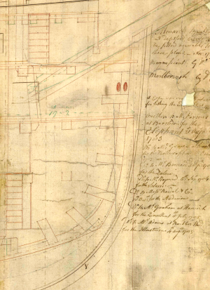
warren

- Joined
- Oct 23, 2018
- Messages
- 886
- Points
- 403

The dashed line shows the position of the connection of the upper stem and the upper apron. The rabbet is at the upper stem in the middle of the part.
The Culloden contract shows the dimension as 11 inches as does another contract for a 74 from 1781 so I think you are good to go.To a very close approximation, the line is 11 inches from the joint between the Stemson and the Apron. Would this show as built or as designed? Does it indicate something else? For what its worth, Bombay Castle (quazi sister ship) contract requires an 11inch Apron.
Would it be safe to assume that most of the dashed lines indicated joints/interfaces between wooden parts?
Dashed lines were sometimes, not always, used to show center lines (see the bowsprit in the drawing your post 51) alternate and as-built versus original locations, hidden objects, etc. For example black lines show the original design, green lines show as built and dashed lines show parts of the fir ships of the Artois class (such as Diana) all on the same drawing. I tried to attach it but it is too large (60mb). You can download it from the WikiCommons site and blow it up to see a number of examples in good detail.
 commons.wikimedia.org
Allan
PS: If it does not open right to the inboard profile drawing, it is the fifth from last one on page four of the lists of drawings.
Category:Ship plans of the Royal Museums Greenwich - Wikimedia Commons
PS: If it does not open right to the inboard profile drawing, it is the fifth from last one on page four of the lists of drawings.
Thank you Allen. The link opened the Artois class drawing. The hidden ladders I understand. Most of the dashed lines at the Stem I understand. Why the dashed line down the keelson ? I assume that is the interface between the deadwood and the keelson.
warren
warren
Last edited:
Thank you ChristianThe dashed line shows the position of the connection of the upper stem and the upper apron. The rabbet is at the upper stem in the middle of the part.
The hidden ladders I understand
I don't think those are hidden ladders, but rather strengthening timbers attached to the hull on the fir built ships of the Artois class, those being HMS Clyde and HMS Tamar.
I am sure it is a terminology thing, but there is no dashed line between the false keel, which is on the underside of the keel, and the keel itself.Why the dashed line down the keel vs the solid line shown between the keel and the false keel?
I am guessing you are referring to the keelson (kelson). Note how the main mast step, shot lockers, and other items end on the dotted line. I THINK the dotted line has to do with the things that straddle the keelson. Look at the posts aft supporting the mizzen mast step and they sit on top of the keelson rather than straddle it. I hope someone has a clear answer as I am super curious about this. Thanks for bringing attention to this dotted line.
Allan
I have been looking at possible reasons for the dashed line on the keelson (Bellona dwg). Lavery shows, in figure B19, the Limber board spanning a space between the Keelson and "strakes next the limbers." The distance from the bottom of the keelson to the dashed line measures 6 inches for the entire length of the keelson. Reading the Bombay Castle contract, the Limber Boards are to be 3 in English Oak. More interesting is the "Strake Next the Limbers." They are to be 7 1/2 inches thick. It then says a second strake that shall measure 6 1/2 in thick. Might these be the dashed line?
warren
warren
Last edited:
I commented on Jimsky's "cost of scratch build vs...(https://shipsofscale.com/sosforums/...uild-a-real-divide-or-just-perspective.17052/)" and thought I would expand as it relates to my Bellona.
If you are willing to build a kit per the instructions (no bashing) I'm reasonably certain that even an expensive kit is cheaper than a scratch build.
Lets now assume that you are not a tolerant kit builder. Where do you draw the line. The minute you begin researching the target ship you are in the world of scratch build. Where do you draw the line?
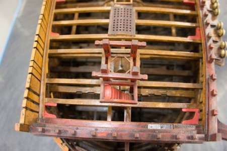
S. J. Soane of "Modelshipworld" has not, to date, made any compromises. He has the crew of Navel Research Guild at his shoulder helping research any and all topics (wonder how the captain's seat of ease is plumbed?). If I ever make sawdust I have his shoulders to stand on.
If you have read any of this log you can see that I have been very frustrated at times. I realize now that my goal has to be reduced to "the best I can do." and how much I'm willing to spend.
At the moment I am stalled on lofting the cant frames at her stern. I only have 18 frames to go but I realize getting the spacing correct is an iterative process. It took me 4 days to do the stem. I am still on the half breadth. Once I am happy with the cant frames I have to project them to the profile view. Tedious is an understatement (for me anyway).
So, what to do? AllenKP69 has kindly offered comments on ships cannons. Although I won't need them for a year or so I thought this would be an interesting rabbit hole to climb into. The details are readily available as are STL files for all 4 guns used on Bellona.
I have sent a sample to a local printer for a quote. When Soane did the same the quote came back as $850 - $1200 (from memory.). He went off and cast the cannons in pewter. Hmmm. Crucible, tongs, pewter, molds. Oh yea, 4 brass masters. The list goes on.
I have a lathe (actually 2) and am competent at such. Machine 74 cannons in brass? Machine 4 as masters? Is this necessary just to stay with the tradition of brass cannons?
So lets say my local printer comes back with any estimate in excess of $200. I can buy a resin printer on Amazon for <$200. Not sure what resin costs but I'm sure it is under $100. If I buy the printer I can do all of my carvings in plastic. Hmmm. Here we are again dealing with tradition. Is my carving good enough.....?
The horse has stopped breathing. I guess I have beaten it to death.
warren


