Thank you. I have that but stopped using it for some reason.
-

Win a Free Custom Engraved Brass Coin!!!
As a way to introduce our brass coins to the community, we will raffle off a free coin during the month of August. Follow link ABOVE for instructions for entering.
-

PRE-ORDER SHIPS IN SCALE TODAY!
The beloved Ships in Scale Magazine is back and charting a new course for 2026!
Discover new skills, new techniques, and new inspirations in every issue.
NOTE THAT OUR FIRST ISSUE WILL BE JAN/FEB 2026
You are using an out of date browser. It may not display this or other websites correctly.
You should upgrade or use an alternative browser.
You should upgrade or use an alternative browser.
The following is a bit embarrassing but I will share anyway.
I have read Harold Underhill's "Plank On Frame Models" up to but not including Planking The Hull. He is very detailed and provides excellent guidance for one wishing to build a plank on frame model. He does explain how to "lift" curves from a ship's line drawing. He even provides drawings to refer to. However, the drawings are reduced to 6 1/2 inches by 9 1/2 inches making them difficult to follow.
In his discussion about taking off frames he skips over cant frames and refers you to his "Leon" plans. These are 1/8th scale drawings for a 110.7 foot ship again reduced to fit on a 6 1/2 x 9 1/2 page. The text is unreadable, even with a magnifying glass. At this point I am at the same place I was in post #73
As mentioned earlier I was able to find draughts for Boreas.
I imported them as designed, as built and frame deposition drawings into LibreCAD. I only traced what was absolutely necessary to allow me to project the stern cant frames overlaid on the half breadth plan to the frame disposition plan. As a reminder, this is the ship that Wayne Kempson used in his CAD document. Kempson does not show his projections so he avoids the problem I am running into. I'm a retired engineer as such I was trained to cross check my work whenever possible. I have been doing that for this endeavor. I do not like the results. In the attached screen shots I have circled the major excursions of a cant frame as projected on the frame disposition drawing.
At this point, I think I can work around this as the frame disposition drawing does not seem to add much to the construction effort.
I guess at this point I have to just muddle along and see if Kempson can show me how to develop frames.
Attachments
- Joined
- Oct 23, 2018
- Messages
- 886
- Points
- 403

Warren,
Do I have something missed? I could not find any hint on the line drawings, you need. The first step is allways the design of the body plan, the horizontal and buttock lines and also the diagonal lines. If everything matchs you can begin with the backbone and the inboard profile . After this you can start with the frame design.
Do I have something missed? I could not find any hint on the line drawings, you need. The first step is allways the design of the body plan, the horizontal and buttock lines and also the diagonal lines. If everything matchs you can begin with the backbone and the inboard profile . After this you can start with the frame design.
H Christian
Thank you for your patience. I don't think you have missed anything. I might not be explaining things clearly. My last exercise was a check on my understanding of Kempson's design process. I think I understand him but I do not like the results.
The problem for me is that everything does not match. This is why the exercise with Boreas. I tried to show the problem in my last post. To me, the circled areas should lie on one and only one frame. They do not. The lines I circled cross to adjacent frames.
For Bellona, I traced the sheer plan, the body plan and the half breadth plan.
Kempson goes through an exercise where all of the original lines are re-generated. I followed all of this. In the end, while creating the cant frames my generated frames do not match the original in the frame disposition drawings.
I know I can create the square frames I worry about the cant frames.
warren
Here is a different approach:
The red lines are projections from one cant frame as it crosses the water lines in the sheer view. The underlying image is the frame disposition drawing. The green line is the projected lines as they cross the water lines in the disposition drawing. The line should be straight. I believe I am doing the projections correctly which means the cant frames in the disposition drawing are not realistic.
Anyone care to comment? I am really frustrated by this.
warren
Attachments
- Joined
- Oct 23, 2018
- Messages
- 886
- Points
- 403

I will compare your result with my reconstruction of the Triton. I do not trace the given lines. I use them to define the radii of the different circles. There are always inaccuracies in the historical drawings. So it is quite normal that the line do not match well . If you compare different drawings from the same ship, they do also not match in every part.
We don’t know, which lines they used to create the drawing.
The problems at the bottom of your DoF are incorrect body lines, which gives you false horizontal lines. That’s the reason for the question in my last post.
We don’t know, which lines they used to create the drawing.
The problems at the bottom of your DoF are incorrect body lines, which gives you false horizontal lines. That’s the reason for the question in my last post.
Last edited:
I am beginning to understand. I have been reviewing William Sutherland's work as well as "Understand Ship Draughts by Dave White. I am following their descriptions and trying to find the centers of the circles. For Bellona, I can use some of the construction marks in the body plan to generate the circles but not all of them. I see a similar problem trying to generate the Triton circles from the body plan. I can generate the circles by using a circle tool that generates the circle by defining 3 points. Is that how you create your body plan?I will compare your result with my reconstruction of the Triton. I do not trace the given lines. I use them to define the radii of the different circles. There are always inaccuracies in the historical drawings. So it is quite normal that the line do not match well . If you compare different drawings from the same ship, they do also not match in every part.
We don’t know, which lines they used to create the drawing.
The problems at the bottom of your DoF are incorrect body lines, which gives you false horizontal lines. That’s the reason for the question in my last post.
I ask as I am thinking about starting over, generate the body plan and go from there.
By the way, thank you again for your help. I hope others are looking in and learning something from this.
Warren
- Joined
- Oct 23, 2018
- Messages
- 886
- Points
- 403

Hallo Warren,
You do not need always 3 points on a circle. I use more often one or two points and tangents to the other parts of the same body line. Before you start with the body lines, you must define the station lines, breadth extreme and further construction lines in the profile and horizontal view.
I am thinking, how I can show you (and perhaps other interested members of the forum) my way to do the job. But this needs a lot of preparation. I have Aetna (a bomb vessel from 1776) in mind which is not as big as a frigate or a ship of the line. As I remember right all historical drawings are available via the Wikimedia Common.
I have been thinking about this. From my earlier attempt I have station lines that agree with the stated room and space. I have added my own waterlines to the sheer plan and the body plan. I think I have to assume that the general shape of the ship, as shown in the sheer and the half breadth plan are correct.
I tried drawing two frames yesterday. I can fit parts of circles to many curves but not all. When I traced the body drawing I was lost near the dead flat areas. The lines were too fuzzy. My body plan has the centers and radii for many of the curves. I realized that I do not have an accurate radius for the curves near the dead flat. I then realized that I can measure these distances on the half breadth (horizontal) plan and use these for the radii.
I am putting together a plan to figure out what information I have, what I have to assume to be correct, and what curves I can generate using circles. I thought I would try fitting some of the curves to Sutherland's just to see if they apply.
warren
Edit: The lines on the half breadth to not indicate the radius for the max breadth curves. Further, measuring the radii on the body plan and entering that for the radius of a circle is no guarantee that the circle will overlay part of the target curve. So much more to learn about the accuracy of these draughts.
Last edited:
- Joined
- Oct 23, 2018
- Messages
- 886
- Points
- 403

See attached a screehot of the reconstruction of Comet. On top of historical drawing you can see my reconstructed lines. The small differences are quite normal as result of the design process.
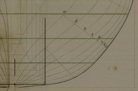
I started this morning with the line drawing of Aetna. Please give me a little bit time to show you my way.

I started this morning with the line drawing of Aetna. Please give me a little bit time to show you my way.
Take your time, I am extreemly interested but not in a hurry
I have been reading and re-reading David White's "Understanding Ship's draughts." Trying to fill in blanks I have also been looking to Sutherland and Steel. As a lab exercise (didn't I tell you I went to a technical college?) I copied the Bellona body drawing into a new work space and tried generating circles using the available centers and radii of curves found on the drawing. I then used a 3 point circle tool and attempted to re-generate the curves that had no supporting data. Lastly, I used straight lines to fill gaps between the circles. I have left the circles intact just for this exercise. I also have the body drawing in the background.
For the attached drawing I located the largest error between the new curves and the body drawing. If my arithmetic is correct, the error is 1 inch at full scale.
Christian has been providing some insight. I am hoping I am going down the path he suggests.
Anyway, enough stalling. I have archived all of my CAD work to date. Of course I borrowed the basic material I will need to go forward. I am going to start over on my drawings. First I will clean up the body dwg (see attachment) and generate all of the curves in the body drawing using arcs. I will only use straight lines when absolutely needed. From there the plan is to go back to Kempson's CAD guidelines and generate the half breadth and sheer plans.
warren
Edit: attachment is a PDF. Thanks for the heads up.
Attachments
Last edited:
- Joined
- Oct 23, 2018
- Messages
- 886
- Points
- 403

Hi Warren,
it is better to share your results as image (jpg) or as pdf file. There is allways a risc to download and open the old doc-format.
it is better to share your results as image (jpg) or as pdf file. There is allways a risc to download and open the old doc-format.
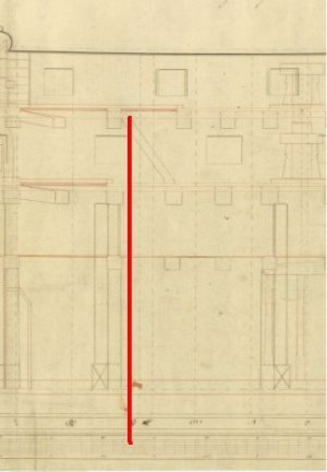
Yet another question. The attachment is a close up of a Bellona Sheer plan in the mid ship area. I was under the belief that the center mark would lie on a bend's joint. The mark appears to me mid "frame". It also appears that the same size frames are not centered on the mark. Can someone explain what I am looking at?
warren
warren
Attachments
It also appears that the same size frames are not centered on the mark
Do you mean where two frames are next to each other? If that is correct I think you are right. Looking at several framing dispositions for 74s at the time of Bellona, all frames are on each side of the station lines and the midships station is indeed the join of two frames. One example is belowI was under the belief that the center mark would lie on a bend's joint.
Allan
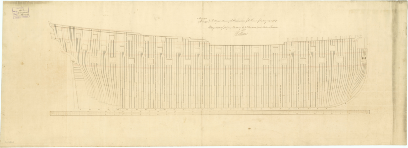
I cannot tell from your image. Looking at my attachment, I see the station marks at 2, (3), (2), (1), X, (B), A. 2 and A are normal station lines. As I understand it, the other 5 are similar frames. The X should mark the dead flat but I thought it would be at a join line, not the middle of a frame and not off to one side in a group of similar frames. I still think I am missing something.
warren
warren
- Joined
- Oct 23, 2018
- Messages
- 886
- Points
- 403

The dead flat is marked by two lines. I would say that there is one single frame between the two stations lines for the x and two frame left and right of each other station lines. The in the sheer plan drawn line are normally showing the double frames, the other ones are single frames. At (3), (1) and (B) are double frames. In my opinion it‘s possible that (1) and X are building a triple frame.
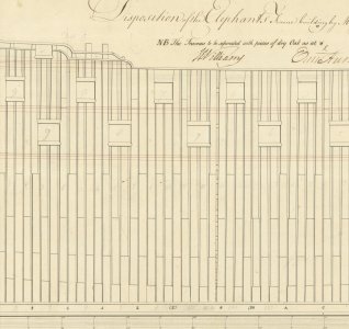
The below may be more clear. The first is a portion of a high res drawng of Elephant (74) 1781. In this case there are three frames at midships with the forward most sitting on the midships station Ø and what Steel calls the Dead-Flat nearly area from frame (2) aft to frame (C) forward. The second drawing of Rodney has only two frames at midships plus several more in the Dead-Flat nearly area.
Allan
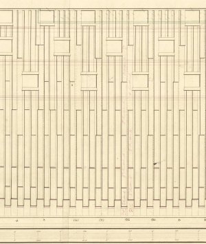
Allan


Last edited:
Christian, Allan
Thank you. I can see my error. I have been under the impression that the midship station had to be in the join of a bend. I can see from Allan's images that it can be in the center of a frame OR in the join.
Thank you again for your patience with this old man.
warren
Thank you. I can see my error. I have been under the impression that the midship station had to be in the join of a bend. I can see from Allan's images that it can be in the center of a frame OR in the join.
Thank you again for your patience with this old man.
warren
It definitely varied. Unless you can find a framing disposition of Bellona I would go with her inboard profile plan (below). You can see that the midships mark was changed and moved slightly aft. Taking into account the aft edge of the frame that would form the forward edge of the gun port (red line below), it seems that for Bellona midships was in between frames.I can see from Allan's images that it can be in the center of a frame OR in the join.
Allan
