Black Pearl 1:50 ZHL

I’ve slowed down on working on this a bit. It’s spring in Western Colorado and spring is the time of year I have the least amount of hobby time. On top of the usual spring stuff like the yard etc. we’ve been camping already and have travels as well. Still I have been getting a little done.

I received the remote from Vic as I mentioned earlier, so finally here’s some pictures with the lights on. Thanks again to Vic.

View attachment 230073

View attachment 230074

View attachment 230075

View attachment 230076

View attachment 230077

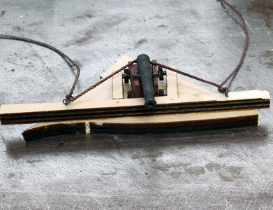
I decided at this point it was time to upgrade the firepower a bit.

View attachment 230078

That is obviously a joke. I painted the base black and stained the coffin with the black stain to make it go with the ship.

View attachment 230079

Next time to get to work on the main deck.
Lookin' good Jodie! If Vic's remote ever craps out, you can have mine too! Know what you mean about spring in the air. We're going to hit upper 80's on Friday and Saturday and the Admiral is demanding beach time. I think my progress will be a bit here and there for a while too!
 
I’ve slowed down on working on this a bit. It’s spring in Western Colorado and spring is the time of year I have the least amount of hobby time. On top of the usual spring stuff like the yard etc. we’ve been camping already and have travels as well. Still I have been getting a little done.

I received the remote from Vic as I mentioned earlier, so finally here’s some pictures with the lights on. Thanks again to Vic.

View attachment 230073

View attachment 230074

View attachment 230075

View attachment 230076

View attachment 230077

I decided at this point it was time to upgrade the firepower a bit.

View attachment 230078

That is obviously a joke. I painted the base black and stained the coffin with the black stain to make it go with the ship.

View attachment 230079

Next time to get to work on the main deck.
You could have at least used a Tiger instead of a T-34!
 
Wow it's been over a month since I posted on this thread. Lots happened in real life during that time.

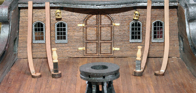
The next step in the manual is the staircases and railings at the back of the main deck. This is a place where from experience I can tell you that you ought to stop and think about what you can do to make the rest of the build easier. Just for starters if you’re going to attach lines from the canons to the bulwarks, It’s infinitely easier to tie the line on to the eyelet off the ship and then glue the eyebolt into the bulwark, than to try and tie the line to the eyebolt while it’s already attached to the bulwarks. It’s also much easier to drill the holes for the eyebolts before adding pin rails and deck furnishings. Also in the case of the the rear stairwells 2 of the canon are behind the stairs so once the stairs are in place it would be hard to work around the canon.

I went ahead and did some of the work for the aft railing and the staircase off the ship.

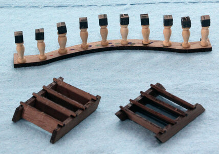
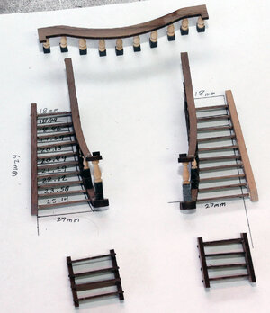
Here’s the railing and the stairs that go on each side to the fore deck. I place the two outer posts on the railing and then calculated and measured the spacing for the 8 posts in the middle. Somehow I calculate the distance wrong the first time and marked it wrong the second time. But! … It isn’t a mistake if you don’t glue it together wrong. Being as these will be painted black the dots won’t show anyway.

BP474.jpg

Next I decided to do some work on the stairs thinking they ought to be reasonably easy to build, and I had a whole afternoon. Once again another bad assumption. For some mysterious reason there are four sets of the curved side rails both upper and lower. When I started I thought that was great because,it would be really easy to mess these up.

BP475.jpg

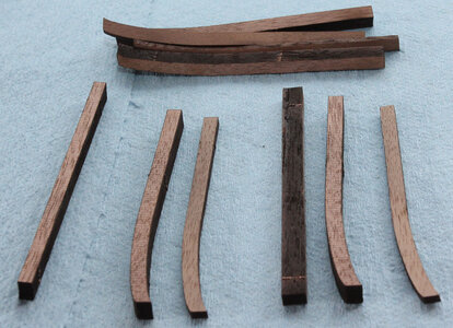
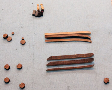
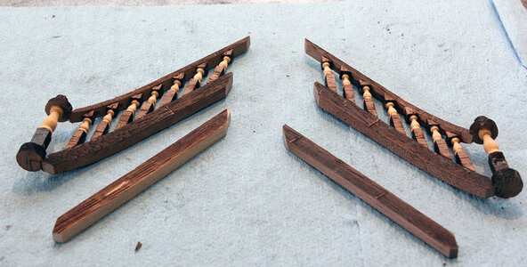
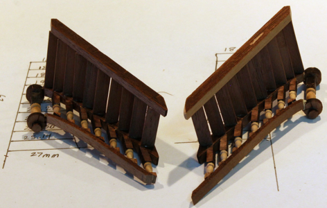
Like most parts of the build the instructions are really cryptic. They tell you the rails on the sides of the stairs should be the same length, and show a photo that doesn’t make much if any sense. After thinking about it a bit and flashing back to geometry I decided it made sense that the 3 rails would all actually need to be the same length looking from the side of the ship for the treads to fit. Here are the parts of the stairs minus the treads.

Edit: Look at the discussion in post #155 in regards to the notches in the round pieces. I think they should be cut to the scored line as opposed to being glued the way I did it.

BP476.jpg

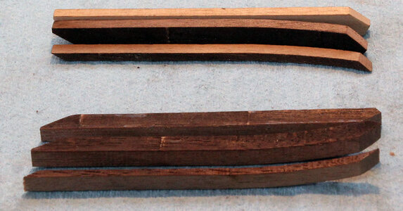
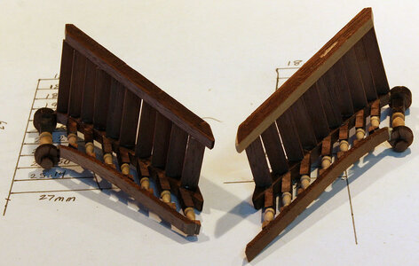
And here is a closer view of the rails and my interpretation of what I believe ZHL intended when they said the rails should be the same length. In the bottom of the photo they’re lying on the side and in the top they are upside down. On the right side of the photo you can see that the wider rails are sanded at two different angles. The short side is where the little round piece attaches to the curved part. I just made the straight one match it in profile.

Also note the straight piece on the top is a different color than the rest of the pieces. That’s because they gave me extra curved pieces, which means of course by Murphy’s law, I screwed up and sanded the angle on one of the straight pieces the wrong direction and had to make a new one. This is why you shouldn’t throw away the scrap pieces from the laser cut sheets, it gives you some extra wood to fix mistakes.

BP477.jpg

I leaned the rails up against the ledge where they attach to figure out the angle to sand them too initially. In the photo below you can see that I glued the round part to the top and bottom rail in place. These are not glued to the deck. The stanchions in the photo are made from a part I believe labeled G6 in the plans, but there are for parts two different lengths under the label. These are the shorter parts under the G6 label.

BP478.jpg

Next I finished building the side rails. I intended to show how I figured the lengths out but next thing I knew it was together and I hadn’t taken any photos. So a little description. The smaller stanchions are made from the little triangular pieces G11, I believe. The longer lower parts are listed as G1 in one of the photos. This threw me because I had some G1 parts left over but not 14 of them. After a lot of looking around I noted that in another photo the lower portion was listed as G9 which is the correct number.

The last piece of the puzzle isthat the G9 parts are flat on both ends. I found that sanding the lower part to match the angle of the triangle on the top but not shortening the overall length of the G9 part,made them the correct size. Here’s a photo.

BP479.jpg

At this point I stopped for the day after realizing that the treads for the stairs had to be cut from a 1mm x 5mm strip of wood. This is another place I’m going to complain a bit. For starters there is no reason not to cut the angle on the bottom of the G9 parts. It’s a pain to sand those tiny things and it wouldn’t take any more time for the laser to cut one end at an angle, just a quick modification of the cutting file. And lastly the treads should be laser cut IMO. For me the whole point of building a kit instead of scratch building everything is to not have to figure out and cut complex angles and curves. In my opinion the treads are a mid level scratch building project. With all the laser cut parts in this kit they should really be laser cut. Instead they laser cut a lot of parts that really are just squares and leave these to the builder. That puzzles me a bit.

I spent a couple weeks being un motivated because I didn’t want to do a scratch biuild type project before I finally moved forward. I also had a vacation and the some family stuff that took priority. When I finally got back to this I formulated the plan below to complete the stair case.

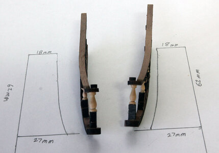
I placed the two rail portions on the ship with the center railing in between and centered. I then measured the width of the top step and the width for the lower deck level. I then drew it on a piece of paper and used the curved rail to draw the opposite side.

BP480.jpg

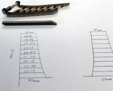
Then I divided the stair into 10 spaces (9 Treads), and here are the lengths I came out with for the steps.

BP481.jpg

Here’s a couple photos after gluing the treads in. I just eyeballed these to square. Probably not the best idea but they came out fine. You could pretty easily build a rectangular jig and make sure the angle is exactly 90 but I’m happy with how it looks now. Here’s a couple photos.

BP482.jpg

BP483.jpg

And a couple photos with them just set in place not glued on. There are canon that go under these and they still need painted.

BP484.jpg

BP485.jpg
 
Last edited:
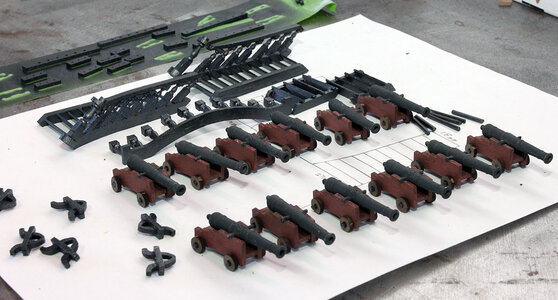
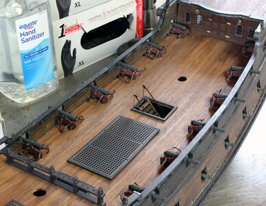
So I went to work finishing the canon. I also took a look at what needed to be done for the pin rails for belaying the rigging at this point. I painted the pin rails and stair cases as well.

BP487.jpg

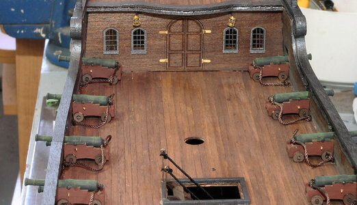
I’m not a big fan of rigging guns. Basically I’m lazy and when the ship is finished the lack of a tom of lines on the guns won’t be very noticeable to the people that will see this thing beyond the pictures on this sight. That being said though I do like the breeching line and think it looks to bare without it. So I made a Jig to tie the breaching lines.

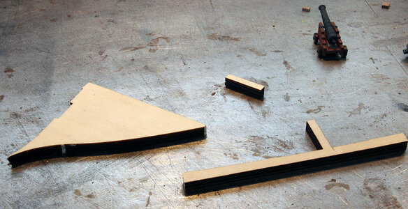
I took some scraps from the laser cut sheets shown below.

BP488.jpg

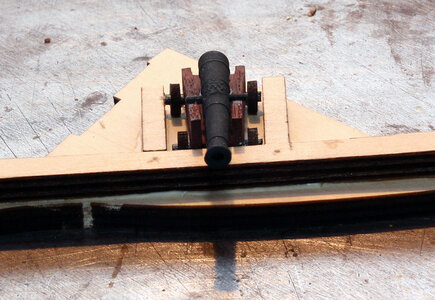
I cut one of the extensions off and glued it to make a holder for the canon. I also drilled 2 holes at the distance I wanted to mount them on the ship.

BP489.jpg

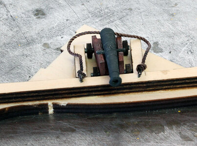
I then tied the first breeching line in the jig. I eyeballed the length of the line to where I was happy with them.

BP490.jpg

Then I drilled 2 holes with the line stretched out tight. On the last eleven canon I just tied the line tight between these three points which made all of the breeching lines very close to the same length. By tying the eyelets on in the jig I was able to just glue the eyes in the holes on the side of the ship instead of trying to tie them in place or making hooks.

BP491.jpg

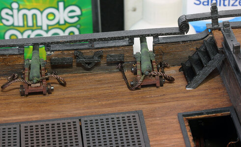
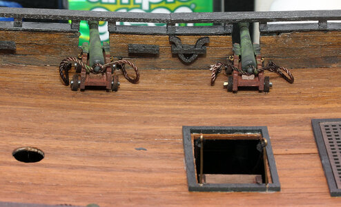
I glued on some caps on the canon barrel and placed eyelets o the sides of the canon like I showed on the lower deck guns. Then I glued the canon on the deck and after the glue setup, I glued the breeching line eyes into the holes I pre-drilled into the deck.

BP492.jpg

I then added some green weathering powder as before. In person the green is much more subtle than it appears in these photos.

BP494.jpg

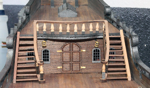
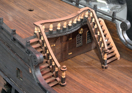
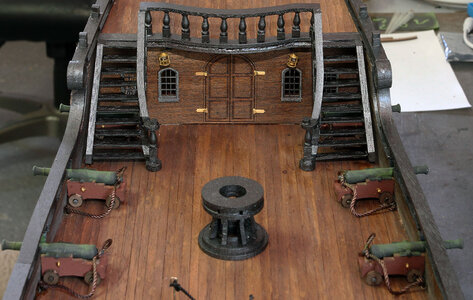
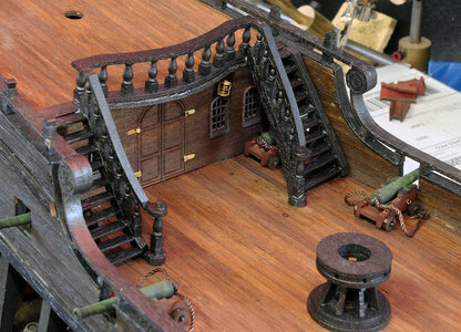
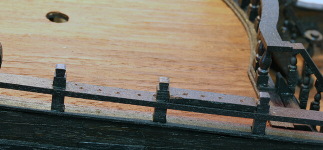
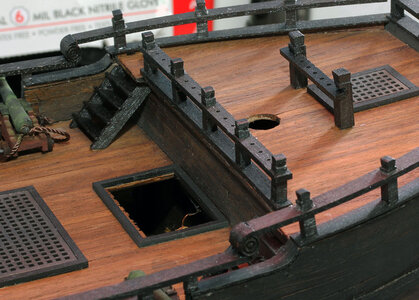
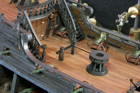
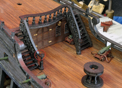
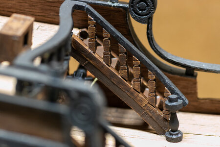
And then finally I glued the aft railing and stair cases into place.

BP495.jpg

Here you can see the guns under the staircase.

BP496.jpg
 
My next mission was to glue the pin rails in place for the belaying pins. I stopped here and spent quite a bit of time looking at the large plan sheets. At first they seemed to be really lacking in information like most of the rest of the instructions; however, after about 30 minutes of study they aren’t really all that horrible in terms of lacking information. That being said though the rigging is a train wreck. I’m not going to pretend to be an expert at rigging. However; zig zagging a line through three blocks and tying it to the bow sprit with 2 more blocks above it, that can’t move, obviously serves no purpose. So I’m planning on winging in some rigging elements similar to some of the other models I’ve rigged that have more believable rigging. The next step was figuring out where they are going to tie off. So I moved some of the pin rails around a bit.

So if when this is done you like the way it’s rigged I’m going to try and give enough info that it can be copied.

So here’s the arrangement I decided to go with. On the front I did just as the instructions indicated. With 2 holes front 3 rear and the davit in the middle.

BP498.jpg

In the middle directly behind the stairwell I placed a davit and 3 hole pin rail.

BP499.jpg

At the base of the stairs I placed a 4 hole section in front of the canon and a 3 hole behind it. The 4 hole section is actually half of the 8 hole pin rail the instructions call for here. The reason I did this is because the longer pin rail would be located half in front of the main mast which seems like an awkward location to affix lines. The other 8 hole section I’ll show later.

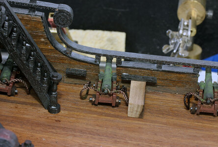
In order to get the pin rails spaced evenly I took a piece of 10mm square wood. (It’s the wood I did not use for the roof on the side galley). I used it to set the height of the rails as I glued them on as seen below.

BP497.jpg

The on the poop deck I placed a 2 hole and a 3 hole pin rail on opposite sides of the davit the instructions called for.

BP500.jpg

I then drilled holes in the rails on the forward portion of the poop deck. The instructions show ropes randomly tied to the rails. I just thought it would be a neater presentation if it had pins. I used a scrap to locate the holes the same on each section.

BP501.jpg

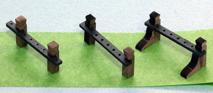
Next I made the two pin rails for the fore mast and mizzen mast as the instructions indicate. I also took the second 8 hole rail mentioned above and made a third rail for the main mast. I searched all over looking for one of the four posts for the pin rails and couldn’t find it. I knew I would eventually but being as I was making another rail I just built three of the posts from scratch. Of course I found the missing part last night it somehow ended up in the compartment with the rope.

BP503.jpg

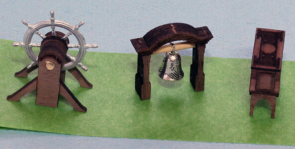
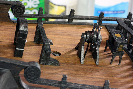
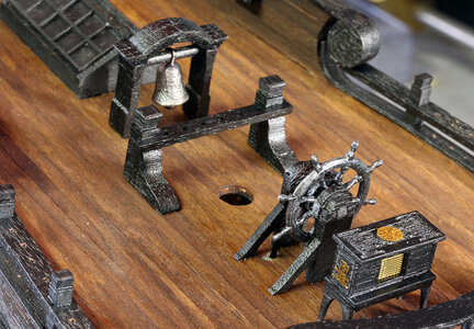
While I was at it I also assembled the wheel, belfry and the cabinet.

BP502.jpg

So for the rigging I placed the foremast pin rail.

BP504.jpg

For the main mast I placed the new pin rail I created back far enough the capstan arms would be able to clear it. While the capstan is clearly a ridiculous prop it looks cool so I wanted to keep it but didn’t want to route the ropes that should go to the bottom of the main mast to the sides as I think it would look like a rats nest. So my plan is to tie these lines back a way but still in the center of the ship.

BP505.jpg

And finally the rear is in the kit position. That completes what I did so far. Bafore I start rigging I’ll add a bunch more attachments outside the hull etc. but that will come later.

Also note that I wrapped rope around the wheel and then ran it straight down into holes in the deck. The rope doesn’t actually go anywhere it is soaked with CA and only extends about 1/8” into the deck.

BP507.jpg

On the cabinet in the front I added a few photoetched brass bits I had lying around. The compass is actually a N-scale table for a train layout with the side decorations actually being chair backs and the grid is a walkway for the train layout.

BP507b.jpg

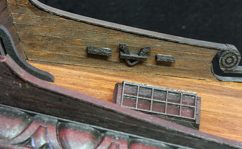
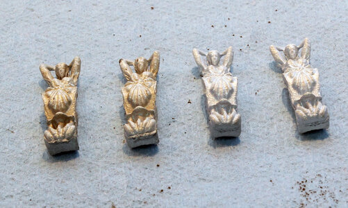
One step in the manual I skipped before now was adding the statues by the Captain’s cabin. In order to get all of the decorations the same I painted them together.

BP508.jpg

At this point the Admiral stopped by and fell in love with the white pearl paint and said I should just use them that way. Initially I was going to darken and then patina them, but I’m building the ship for her so if that’s what she wants it’ll save me time. I did however add a little dust of brownish pastels to tone it down, don’t tell her.

BP509.jpg

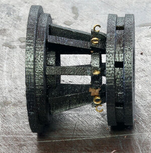
I then drilled and added eyelets to the capstan for the chain. There wasn’t any chain in my kit. I don’t know it I lost it or what, but I had some in my train stuff so I used it.

BP510.jpg

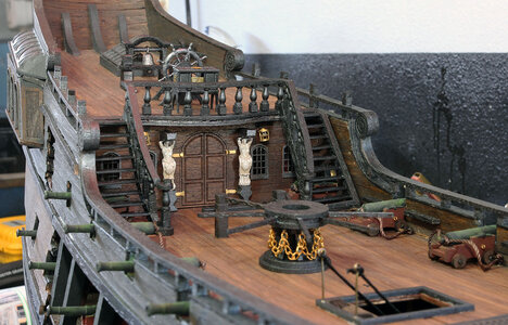
So here are the statues mounted in position. I think the slightly subdued white looks good. And the capstan with the gold chain. I’m going to change my focus to the forcastle next.

BP512.jpg
 
So I went to work finishing the canon. I also took a look at what needed to be done for the pin rails for belaying the rigging at this point. I painted the pin rails and stair cases as well.

View attachment 236725

I’m not a big fan of rigging guns. Basically I’m lazy and when the ship is finished the lack of a tom of lines on the guns won’t be very noticeable to the people that will see this thing beyond the pictures on this sight. That being said though I do like the breeching line and think it looks to bare without it. So I made a Jig to tie the breaching lines.

I took some scraps from the laser cut sheets shown below.

View attachment 236724

I cut one of the extensions off and glued it to make a holder for the canon. I also drilled 2 holes at the distance I wanted to mount them on the ship.

View attachment 236723

I then tied the first breeching line in the jig. I eyeballed the length of the line to where I was happy with them.

View attachment 236722

Then I drilled 2 holes with the line stretched out tight. On the last eleven canon I just tied the line tight between these three points which made all of the breeching lines very close to the same length. By tying the eyelets on in the jig I was able to just glue the eyes in the holes on the side of the ship instead of trying to tie them in place or making hooks.

View attachment 236721

I glued on some caps on the canon barrel and placed eyelets o the sides of the canon like I showed on the lower deck guns. Then I glued the canon on the deck and after the glue setup, I glued the breeching line eyes into the holes I pre-drilled into the deck.

View attachment 236720

I then added some green weathering powder as before. In person the green is much more subtle than it appears in these photos.

View attachment 236719

And then finally I glued the aft railing and stair cases into place.

View attachment 236718

Here you can see the guns under the staircase.

View attachment 236717
That’s a tight fit for those guns under the stairs. You made the stairs look easy.
 
My next mission was to glue the pin rails in place for the belaying pins. I stopped here and spent quite a bit of time looking at the large plan sheets. At first they seemed to be really lacking in information like most of the rest of the instructions; however, after about 30 minutes of study they aren’t really all that horrible in terms of lacking information. That being said though the rigging is a train wreck. I’m not going to pretend to be an expert at rigging. However; zig zagging a line through three blocks and tying it to the bow sprit with 2 more blocks above it, that can’t move, obviously serves no purpose. So I’m planning on winging in some rigging elements similar to some of the other models I’ve rigged that have more believable rigging. The next step was figuring out where they are going to tie off. So I moved some of the pin rails around a bit.

So if when this is done you like the way it’s rigged I’m going to try and give enough info that it can be copied.

So here’s the arrangement I decided to go with. On the front I did just as the instructions indicated. With 2 holes front 3 rear and the davit in the middle.

View attachment 236740

In the middle directly behind the stairwell I placed a davit and 3 hole pin rail.

View attachment 236739

At the base of the stairs I placed a 4 hole section in front of the canon and a 3 hole behind it. The 4 hole section is actually half of the 8 hole pin rail the instructions call for here. The reason I did this is because the longer pin rail would be located half in front of the main mast which seems like an awkward location to affix lines. The other 8 hole section I’ll show later.

In order to get the pin rails spaced evenly I took a piece of 10mm square wood. (It’s the wood I did not use for the roof on the side galley). I used it to set the height of the rails as I glued them on as seen below.

View attachment 236738

The on the poop deck I placed a 2 hole and a 3 hole pin rail on opposite sides of the davit the instructions called for.

View attachment 236737

I then drilled holes in the rails on the forward portion of the poop deck. The instructions show ropes randomly tied to the rails. I just thought it would be a neater presentation if it had pins. I used a scrap to locate the holes the same on each section.

View attachment 236736

Next I made the two pin rails for the fore mast and mizzen mast as the instructions indicate. I also took the second 8 hole rail mentioned above and made a third rail for the main mast. I searched all over looking for one of the four posts for the pin rails and couldn’t find it. I knew I would eventually but being as I was making another rail I just built three of the posts from scratch. Of course I found the missing part last night it somehow ended up in the compartment with the rope.

View attachment 236735

While I was at it I also assembled the wheel, belfry and the cabinet.

View attachment 236734

So for the rigging I placed the foremast pin rail.

View attachment 236733

For the main mast I placed the new pin rail I created back far enough the capstan arms would be able to clear it. While the capstan is clearly a ridiculous prop it looks cool so I wanted to keep it but didn’t want to route the ropes that should go to the bottom of the main mast to the sides as I think it would look like a rats nest. So my plan is to tie these lines back a way but still in the center of the ship.

View attachment 236732

And finally the rear is in the kit position. That completes what I did so far. Bafore I start rigging I’ll add a bunch more attachments outside the hull etc. but that will come later.

Also note that I wrapped rope around the wheel and then ran it straight down into holes in the deck. The rope doesn’t actually go anywhere it is soaked with CA and only extends about 1/8” into the deck.

View attachment 236731

On the cabinet in the front I added a few photoetched brass bits I had lying around. The compass is actually a N-scale table for a train layout with the side decorations actually being chair backs and the grid is a walkway for the train layout.

View attachment 236730

One step in the manual I skipped before now was adding the statues by the Captain’s cabin. In order to get all of the decorations the same I painted them together.

View attachment 236729

At this point the Admiral stopped by and fell in love with the white pearl paint and said I should just use them that way. Initially I was going to darken and then patina them, but I’m building the ship for her so if that’s what she wants it’ll save me time. I did however add a little dust of brownish pastels to tone it down, don’t tell her.

View attachment 236728

I then drilled and added eyelets to the capstan for the chain. There wasn’t any chain in my kit. I don’t know it I lost it or what, but I had some in my train stuff so I used it.

View attachment 236727

So here are the statues mounted in position. I think the slightly subdued white looks good. And the capstan with the gold chain. I’m going to change my focus to the forcastle next.

View attachment 236726
Jodie, fantastic work and great detail explaining so much. I’m sure glad you are leading the way for me on this build and it’s great to have this information! I will have to read this several times and go over it again when I reach this part of my build!
Ahoy!
 
Jodie, you’re doing a great job of explaining the process and your reasoning. I did tie off the main mast rigging on the pin rail. I see you made an extra bit rail for your main mast instead. One thing that bothered me was when I tightened lines to side rails and bits, they sometimes came loose. I had even tried using copper pins to no avail.
 
Thanks for the compliments.

Jimsky - I'll have to take a look at that in person, and see if it stands out. I could always put some putty around it and repaint. I know there isn't actually a gap but it does look that way in the macro photo.

Hind sight being 20/20 as they say; I'm guessing ZHL intended for me to cut the notch to the scored line, you can see in the photo below, in the round pieces so they would fit tighter. That wasn't obvious given that they laser cut a notch on the part to begin with. If it was cut to the scored line on the part in the photo below it would fit better. Possibly even cut to the scored line and flipped over so the longer part of the notch was across the end of the rail.

I'm not tearing it apart now but on my next one I'll cut the notches back :D, Not like I'll ever build another one of these. I did add a note to the post up top so others hopefully wont make the same mistake.

1622644907638.png

Vic - If I remember correctly you were using tongue oil for your finish. I only use water based paint, stain and Shellack, I've never had trouble with PVA glues holding on these finishes. I do airbrush the paint so it's really thin. The glue paint and stain are water based so they play well together. Shellack is basically bug poop dissolved in alcohol. I have no clue why it works but I've never had an issue with PVA glues sticking to it.
 
Last edited:
Thanks for the compliments.

Jimsky - I'll have to take a look at that in person, and see if it stands out. I could always put some putty around it and repaint. I know there isn't actually a gap but it does look that way in the macro photo.

Hind sight being 20/20 as they say; I'm guessing ZHL intended for me to cut the notch to the scored line, you can see in the photo below, in the round pieces so they would fit tighter. That wasn't obvious given that they laser cut a notch on the part to begin with. If it was cut to the scored line on the part in the photo below it would fit better. Possibly even cut to the scored line and flipped over so the longer part of the notch was across the end of the rail.

I'm not tearing it apart now but on my next one I'll cut the notches back :D, Not like I'll ever build another one of these. I did add a note to the post up top so others hopefully wont make the same mistake.

View attachment 236828

Vic - If I remember correctly you were using tongue oil for your finish. I only use water based paint, stain and Shellack, I've never had trouble with PVA glues holding on these finishes. I do airbrush the paint so it's really thin. The glue paint and stain are water based so they play well together. Shellack is basically bug poop dissolved in alcohol. I have no clue why it works but I've never had an issue with PVA glues sticking to it.
Although I like the look of tung oil on wood, I am becoming convinced it doesn’t work well on ships.
 
Although I like the look of tung oil on wood, I am becoming convinced it doesn’t work well on ships.
Tung oil is a good oil for some species of wood. Like other natural oils, it works with some timbers and doesn't with others. When I said works, I mean the surface after you apply it as finishing. Tung oil has the tendency to darken the surface, even after the first coat. It also requires more time to dry before applying the next coat.
 
This is superb work Jodie. Those stair cases seemed to have been a real challenge, but the end result is most satisfactory. Well done Sir!
 
Back
Top