This is all excellent information and work.
You have raised the bar for me, hope I can clear it.
You have raised the bar for me, hope I can clear it.
 |
As a way to introduce our brass coins to the community, we will raffle off a free coin during the month of August. Follow link ABOVE for instructions for entering. |
 |
 |
The beloved Ships in Scale Magazine is back and charting a new course for 2026! Discover new skills, new techniques, and new inspirations in every issue. NOTE THAT OUR FIRST ISSUE WILL BE JAN/FEB 2026 |
 |
Raise your own bar. It will be good.This is all excellent information and work.
You have raised the bar for me, hope I can clear it.
Wow it's been over a month since I posted on this thread. Lots happened in real life during that time.
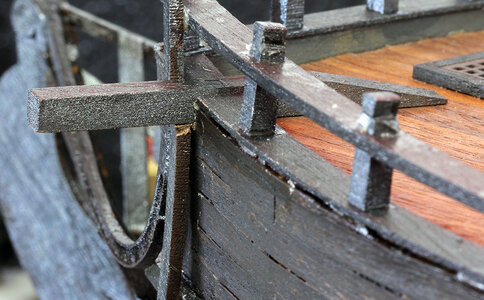
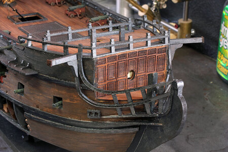
The next step in the manual is the staircases and railings at the back of the main deck. This is a place where from experience I can tell you that you ought to stop and think about what you can do to make the rest of the build easier. Just for starters if you’re going to attach lines from the canons to the bulwarks, It’s infinitely easier to tie the line on to the eyelet off the ship and then glue the eyebolt into the bulwark, than to try and tie the line to the eyebolt while it’s already attached to the bulwarks. It’s also much easier to drill the holes for the eyebolts before adding pin rails and deck furnishings. Also in the case of the the rear stairwells 2 of the canon are behind the stairs so once the stairs are in place it would be hard to work around the canon.
I went ahead and did some of the work for the aft railing and the staircase off the ship.
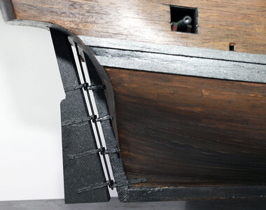
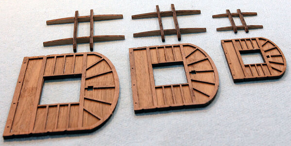
Here’s the railing and the stairs that go on each side to the fore deck. I place the two outer posts on the railing and then calculated and measured the spacing for the 8 posts in the middle. Somehow I calculate the distance wrong the first time and marked it wrong the second time. But! … It isn’t a mistake if you don’t glue it together wrong. Being as these will be painted black the dots won’t show anyway.
View attachment 236704
Next I decided to do some work on the stairs thinking they ought to be reasonably easy to build, and I had a whole afternoon. Once again another bad assumption. For some mysterious reason there are four sets of the curved side rails both upper and lower. When I started I thought that was great because,it would be really easy to mess these up.
View attachment 236705
Like most parts of the build the instructions are really cryptic. They tell you the rails on the sides of the stairs should be the same length, and show a photo that doesn’t make much if any sense. After thinking about it a bit and flashing back to geometry I decided it made sense that the 3 rails would all actually need to be the same length looking from the side of the ship for the treads to fit. Here are the parts of the stairs minus the treads.
Edit: Look at the discussion in post #155 in regards to the notches in the round pieces. I think they should be cut to the scored line as opposed to being glued the way I did it.
View attachment 236706
And here is a closer view of the rails and my interpretation of what I believe ZHL intended when they said the rails should be the same length. In the bottom of the photo they’re lying on the side and in the top they are upside down. On the right side of the photo you can see that the wider rails are sanded at two different angles. The short side is where the little round piece attaches to the curved part. I just made the straight one match it in profile.
Also note the straight piece on the top is a different color than the rest of the pieces. That’s because they gave me extra curved pieces, which means of course by Murphy’s law, I screwed up and sanded the angle on one of the straight pieces the wrong direction and had to make a new one. This is why you shouldn’t throw away the scrap pieces from the laser cut sheets, it gives you some extra wood to fix mistakes.
View attachment 236707
I leaned the rails up against the ledge where they attach to figure out the angle to sand them too initially. In the photo below you can see that I glued the round part to the top and bottom rail in place. These are not glued to the deck. The stanchions in the photo are made from a part I believe labeled G6 in the plans, but there are for parts two different lengths under the label. These are the shorter parts under the G6 label.
View attachment 236708
Next I finished building the side rails. I intended to show how I figured the lengths out but next thing I knew it was together and I hadn’t taken any photos. So a little description. The smaller stanchions are made from the little triangular pieces G11, I believe. The longer lower parts are listed as G1 in one of the photos. This threw me because I had some G1 parts left over but not 14 of them. After a lot of looking around I noted that in another photo the lower portion was listed as G9 which is the correct number.
The last piece of the puzzle isthat the G9 parts are flat on both ends. I found that sanding the lower part to match the angle of the triangle on the top but not shortening the overall length of the G9 part,made them the correct size. Here’s a photo.
View attachment 236709
At this point I stopped for the day after realizing that the treads for the stairs had to be cut from a 1mm x 5mm strip of wood. This is another place I’m going to complain a bit. For starters there is no reason not to cut the angle on the bottom of the G9 parts. It’s a pain to sand those tiny things and it wouldn’t take any more time for the laser to cut one end at an angle, just a quick modification of the cutting file. And lastly the treads should be laser cut IMO. For me the whole point of building a kit instead of scratch building everything is to not have to figure out and cut complex angles and curves. In my opinion the treads are a mid level scratch building project. With all the laser cut parts in this kit they should really be laser cut. Instead they laser cut a lot of parts that really are just squares and leave these to the builder. That puzzles me a bit.
I spent a couple weeks being un motivated because I didn’t want to do a scratch biuild type project before I finally moved forward. I also had a vacation and the some family stuff that took priority. When I finally got back to this I formulated the plan below to complete the stair case.
I placed the two rail portions on the ship with the center railing in between and centered. I then measured the width of the top step and the width for the lower deck level. I then drew it on a piece of paper and used the curved rail to draw the opposite side.
View attachment 236710
Then I divided the stair into 10 spaces (9 Treads), and here are the lengths I came out with for the steps.
View attachment 236711
Here’s a couple photos after gluing the treads in. I just eyeballed these to square. Probably not the best idea but they came out fine. You could pretty easily build a rectangular jig and make sure the angle is exactly 90 but I’m happy with how it looks now. Here’s a couple photos.
View attachment 236712
View attachment 236713
And a couple photos with them just set in place not glued on. There are canon that go under these and they still need painted.
View attachment 236714
View attachment 236715
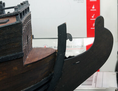
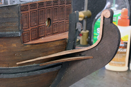
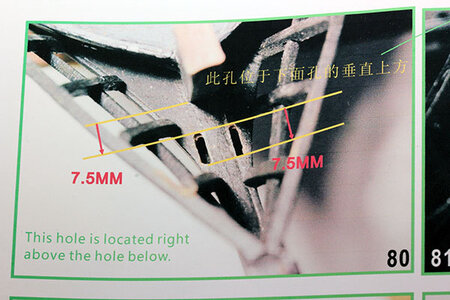
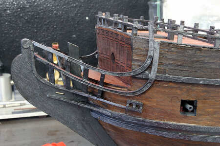
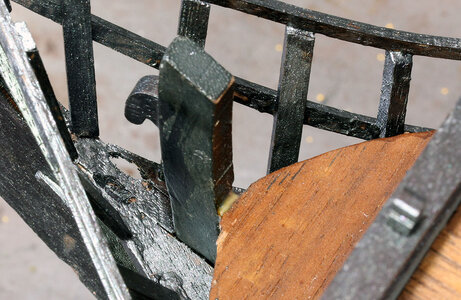
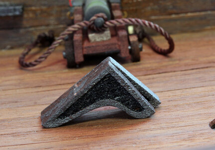
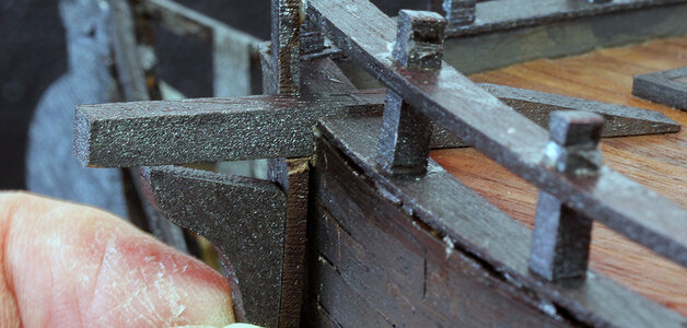
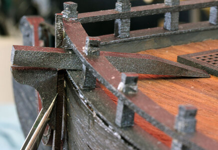

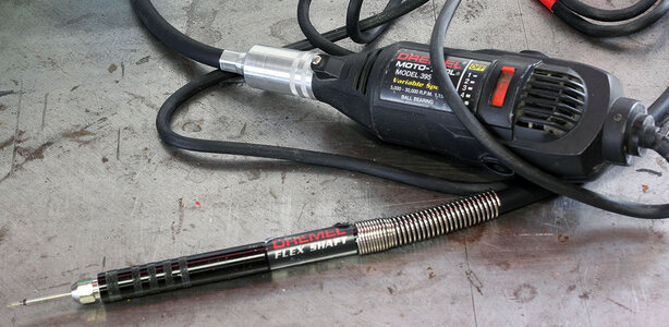
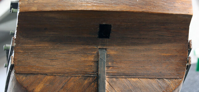
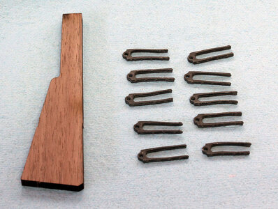
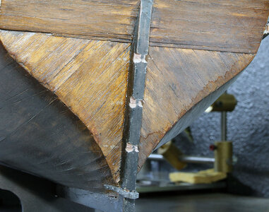
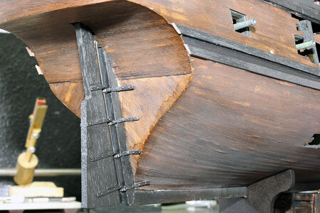

Those hinges were fiddly little things. I did pretty much the same thing on my rudder. I was wondering, did your brackets for the bow piece fit? I wound up just breaking them and gluing what was left in some kind of pattern. Later, when I was working on the rigging, I think, I broke them off and had to reglue them. I was amazed that my gun ports pretty much stayed on. Looking good, Jodie. Some parts look a lot better than mine!At this point I’m getting pretty close to finishing the hull and one of the things I didn’t do yet was attach the rudder. Step I believe 108 has you cut a hole in the bottom of the ship for the top of the rudder. This step should be located clear back just shortly after planking the hull. I’m going to put an edit back in this thread for people that read this later. Being as I hadn’t already done it, and flipping the ship upside down wasn’t really an option at this point, out came the Dremel with the flex shaft.
This should probably have one of those “Don’t try this at home” warning labels. It you’re not really proficient with a Dremel I’d recommend a less nuclear approach. Of course as above hopefull you’ll do this before flipping the ship over becomes a problem.
View attachment 239277
So here is the hole I hacked in. I was pretty pleased being freehand.
View attachment 239279
I’m not a huge fan of bending brass into hinges though I’m sure it works fine. I had the hinges below in my parts box. I don’t even know for sure where they came from. My best guess is a Mamoli Constitution kit I got for $100 off of ebay when I was refurbishing my constitution. At any rate I decided to use them
View attachment 239280
I had to sand the front of the rudder to a radius to fit in the hinges ad then notch the keel as below.
View attachment 239281
I just bent the excess length of the hinge out to the sides. This makes more sense to me that cutting them off. You wouldn’t want only a couple bolts in the keel and four on the rudder, which would happen if these were cut off. I just glued the hinges on.
View attachment 239282
I decided to just go with a solid wire through the hinges because I thought it looked neat. Visually fills up what is probably an overly large gap from the keel to the rudder. Here’s the result.
View attachment 239283
One thing I wanted to mention and should probably show earlier is the framing that goes on the platforms for the mast. Mine ended up pretty broken up by the time I got to this point. I spent a lot of time looking for parts and these are pretty fragile. I would recommend gluing the framing to the platforms much earlier, like the first step when you get to using the second box much. Either that or take that particular laser cut sheet out and set it aside. Here are mine after gluing all the broken parts back together and making filler pieces where I couldn’t find the originals.
View attachment 239284
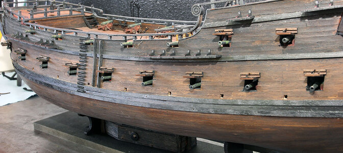
Next up was the gun port covers. I have to say rite up front that this has always been my nemesis in the ship modeling world. I’m not sure if it’s just my lack of patients or the fact that by the time I get to this point I’m tired of tedious little pieces of wood projects. But I never do a very good job on these. I’ll go ahead and show what I did, and then go sit in the corner for a while. Definitely find somewhere else to see how to do this rite.
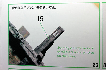
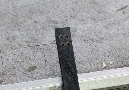
Once again ZHL wants you to drill rectangular holes for the brass struts that hold the rope above the port. Then they want you to build the brass hinges with a nail for the hinge rod that goes in the side of the ship. My favorite part is they show you that in the instructions; and then in the next photo you can see that they failed to accomplish that task themselves, and just glued the back of the hinges to the side of the ship. Clearly that will result in repeatedly knocking the lids off because gluing such a small piece of brass to wood is going to be a really weak joint. I'm way beyond this point in the build rite now but as I type this I’m thinking I should just draw up some gun port lids and have them printed if I do another ship that needs them. That would allow me to mold in pins to attach them to the side of the ship. Could even print the ropes with it. That’s a project for another time.
What I did was cut the back of the hinges off and made an L shaped piece I could glue to the top of the gun port. I used it to hold the line from the port lid. This allows me to glue the wood to the side of the ship and should make the lids really sturdy.
View attachment 239286
I wouldn’t recommend this but on the overall ship they will do the trick. I don’t expect anyone who sees this anywhere but here on the forum would think there was anything wrong here. So this is how it looks.
View attachment 239287

Jodie, great write-up....boy I’m glad I had Vic and you to follow because we have the same version of the Pearl! I’m also picking up a lot from the guys with the Golden Pearl version too! I finally fit my main deck and finished up everything on the gun deck....tomorrow is main deck gluing! Thanks again for all the tips you are sharing.At this point I’m getting pretty close to finishing the hull and one of the things I didn’t do yet was attach the rudder. Step I believe 108 has you cut a hole in the bottom of the ship for the top of the rudder. This step should be located clear back just shortly after planking the hull. I’m going to put an edit back in this thread for people that read this later. Being as I hadn’t already done it, and flipping the ship upside down wasn’t really an option at this point, out came the Dremel with the flex shaft.
This should probably have one of those “Don’t try this at home” warning labels. It you’re not really proficient with a Dremel I’d recommend a less nuclear approach. Of course as above hopefull you’ll do this before flipping the ship over becomes a problem.
View attachment 239277
So here is the hole I hacked in. I was pretty pleased being freehand.
View attachment 239279
I’m not a huge fan of bending brass into hinges though I’m sure it works fine. I had the hinges below in my parts box. I don’t even know for sure where they came from. My best guess is a Mamoli Constitution kit I got for $100 off of ebay when I was refurbishing my constitution. At any rate I decided to use them
View attachment 239280
I had to sand the front of the rudder to a radius to fit in the hinges ad then notch the keel as below.
View attachment 239281
I just bent the excess length of the hinge out to the sides. This makes more sense to me that cutting them off. You wouldn’t want only a couple bolts in the keel and four on the rudder, which would happen if these were cut off. I just glued the hinges on.
View attachment 239282
I decided to just go with a solid wire through the hinges because I thought it looked neat. Visually fills up what is probably an overly large gap from the keel to the rudder. Here’s the result.
View attachment 239283
One thing I wanted to mention and should probably show earlier is the framing that goes on the platforms for the mast. Mine ended up pretty broken up by the time I got to this point. I spent a lot of time looking for parts and these are pretty fragile. I would recommend gluing the framing to the platforms much earlier, like the first step when you get to using the second box much. Either that or take that particular laser cut sheet out and set it aside. Here are mine after gluing all the broken parts back together and making filler pieces where I couldn’t find the originals.
View attachment 239284
Next up was the gun port covers. I have to say rite up front that this has always been my nemesis in the ship modeling world. I’m not sure if it’s just my lack of patients or the fact that by the time I get to this point I’m tired of tedious little pieces of wood projects. But I never do a very good job on these. I’ll go ahead and show what I did, and then go sit in the corner for a while. Definitely find somewhere else to see how to do this rite.
Once again ZHL wants you to drill rectangular holes for the brass struts that hold the rope above the port. Then they want you to build the brass hinges with a nail for the hinge rod that goes in the side of the ship. My favorite part is they show you that in the instructions; and then in the next photo you can see that they failed to accomplish that task themselves, and just glued the back of the hinges to the side of the ship. Clearly that will result in repeatedly knocking the lids off because gluing such a small piece of brass to wood is going to be a really weak joint. I'm way beyond this point in the build rite now but as I type this I’m thinking I should just draw up some gun port lids and have them printed if I do another ship that needs them. That would allow me to mold in pins to attach them to the side of the ship. Could even print the ropes with it. That’s a project for another time.
What I did was cut the back of the hinges off and made an L shaped piece I could glue to the top of the gun port. I used it to hold the line from the port lid. This allows me to glue the wood to the side of the ship and should make the lids really sturdy.
View attachment 239286
I wouldn’t recommend this but on the overall ship they will do the trick. I don’t expect anyone who sees this anywhere but here on the forum would think there was anything wrong here. So this is how it looks.
View attachment 239287
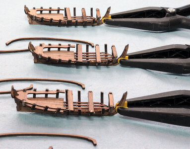
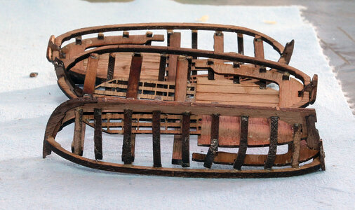
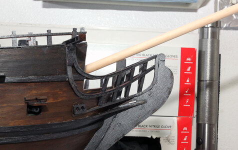
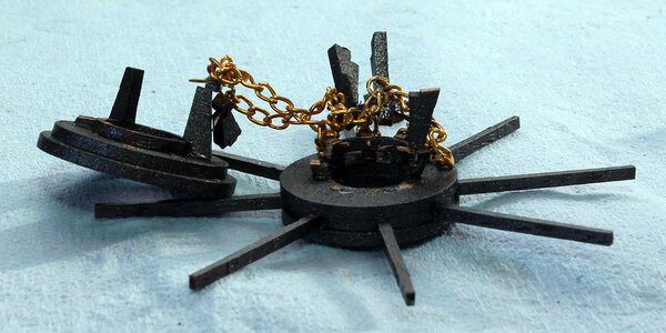
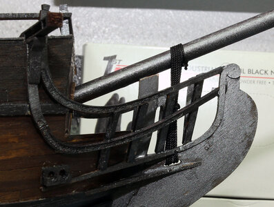
 so who am I kidding here?
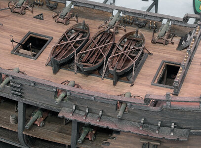
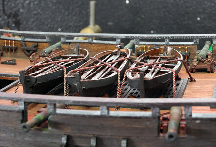
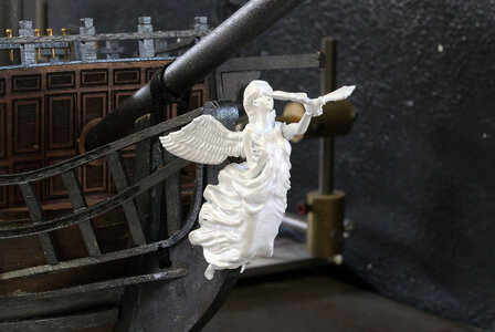
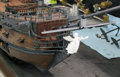
I’m there with you, Buddy! I broke so many pieces in the process of making the boats, I only had enough pieces left for two of them. And those two boats had issues. I did manage to get them planked. There were spaces between the planks, but I filled them with glue and sawdust. After placing the boats on the hatch, I noticed you couldn’t see much detail on the hulls anyway. And the capstan gave me nightmares. I built it after installing the mast, only to discover I couldn’t drill holes for the hooks from the rear because of lack of room for my Dremel. I opted to delete the extraneous chain. I think we both did fine, considering. I love the model. The instructions leave much to be desired.A week after the fiasco above, I decided I wanted to do something but didn’t feel like doing the life boat planking or other logical things so I went ahead and mounted the figurehead. I used epoxy to both glue this on and glue the wings and arm on. It was a bit of a chore waiting for it to set up but think you really need to wait on at least the arm to make sure it looks correct with the angle of the bow sprit. The arm is pinned in but there is quite a bit of play in the joint. Like the rest of the statues I think it’s too white but the admiral likes it. I’m guessing it’ll somehow weather a little more than you might expect something just sitting on a shelf to do in a fairly short period of time.
View attachment 242395
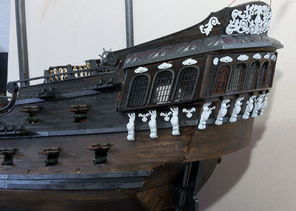
I then went ahead and attached the rear decorations as well. Part of the reason I did this it I’m going to embellish the rigging from what is shown in the plans and need to make sure I can attach extra lines in certain general locations and miss the decoration.
View attachment 242396
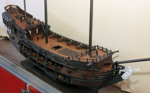
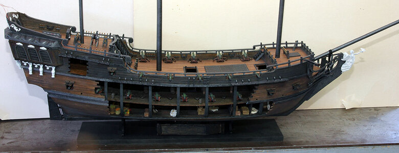
Here’s a view of where I’m at, at this point. Somewhere along the way I glued in the belaying pins in all of the holes I made for them along with the ones shown in the manual. I had to but about 20 extra pins from model expo to fill in all the holes, and left them bare brass for decorative purposes.
View attachment 242397
View attachment 242398
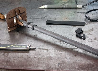
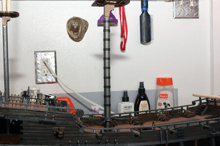
My next little project before I got to where I couldn’t do it, was to make some fake mast hoops, wooldings, wingdings, whatever you want to call them. I decided to take the lazy way out and just cut a bunch of electrical heat shrink to the same width, which I just eyeballed the first one, and made the rest the same. This has to be done before you put something in the way of sliding the heat shrink up the mast if you’re going to do it.
View attachment 242399
And here’s what it looks like when it’s done. I did all three masts.
View attachment 242400
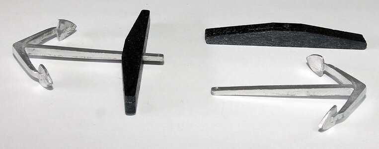
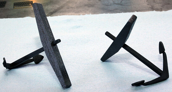
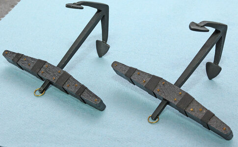
The next thing I decided to do having put it off for quite a while is to detail the anchors. The rings on the anchor are once again, electric heat shrink, and then I drilled it for the copper nails, and added the brass rings.
View attachment 242401
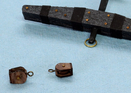
I then made the big blocks for holding the anchors from the catheads. I just set these parts aside as the anchors are huge and I think they will likely be in the way while rigging and I think one end needs to wedged in around the deadeyes for the foremast.
View attachment 242402
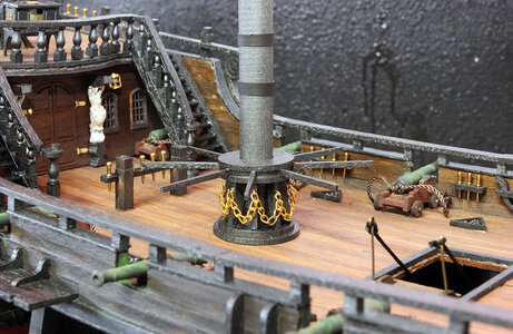
I then rebuilt the capstan around the bottom of the main mast. I tossed out the broken parts that were originally on the capstan and just replaced them with pieces of a 1mm X 4mm strip of wood cut to length and angled a bit on the ends. Then added the hooks and chain like I did originally. I think it looks fine. I’d highly recommend waiting till you’re ready to prep the main mast before building the capstan and then just built it around the mast. You could do it earlier than this point in the build. But built it around the mast.
View attachment 242403
Now I need to acknowledge the advice I gave to @Jeff T to fix his deadeye layout. I should have re-built these boats correctly. I feel a bit of a hypocrite, like a smoker telling someone not to smoke. So sorry Jeff no offense met I should fix these. I know I'm not following my own advice here.
My next mission was to turn my attention back to planking the lifeboats. I carefully and painstakingly formed the strakes from fine ebony and blood wood taking about a day per plank until the upper railings were perfectly aligned within a tenth of mm. Then formed the garboard strake from fresh sawn Alaskan cedar because of the wonderful flexibility of the freshly cut planks.so who am I kidding here?
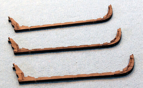
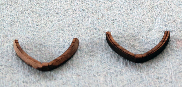
I successfully built several small lifeboats similar to these in the past, but this just wasn’t going to happen. What happened next was a full on soup sandwich. I tried at least 3 times to get the upper rails to match up with barely passable results, followed by totally failing to get the next plank down to fit. My original framing was out of whack to the point of forcing the outer plank wide making it too short to work. I ended up cutting a portion on the front framing off so the planks could reach the stem. And finally after getting the upper planks in place and trying three times to form the next plank down, I just gave up on the idea of planking these things with wood at all. So I tried card stock with about the same results I planked one side of one boat. It looked so bad with the gaps I tore that off and moved to plan G. That’s G for Gorilla Tape.
Basically I just don’t have the patients at this point to spend a couple weeks working on planking life boats. So In my haste, I planked them with strips of Gorilla Tape. Here’s the results. It’s not great, but for 20 minutes work and a little painting It’s good enough for me.
View attachment 242404
View attachment 242405

Wow! Jodie I don’t know where to start! From the anchors to the bow spirit to the lifeboats….so much information! I appreciate all the info you are providing us novices! Your Pearl is really looking great! I keep referring back to Vic’s and your builds! I’m finishing up the Captain’s Quarters this week and I have a lot of soldering up next with some crazy light options! Keep the updates coming! Thanks!A week after the fiasco above, I decided I wanted to do something but didn’t feel like doing the life boat planking or other logical things so I went ahead and mounted the figurehead. I used epoxy to both glue this on and glue the wings and arm on. It was a bit of a chore waiting for it to set up but think you really need to wait on at least the arm to make sure it looks correct with the angle of the bow sprit. The arm is pinned in but there is quite a bit of play in the joint. Like the rest of the statues I think it’s too white but the admiral likes it. I’m guessing it’ll somehow weather a little more than you might expect something just sitting on a shelf to do in a fairly short period of time.
View attachment 242395
I then went ahead and attached the rear decorations as well. Part of the reason I did this it I’m going to embellish the rigging from what is shown in the plans and need to make sure I can attach extra lines in certain general locations and miss the decoration.
View attachment 242396
Here’s a view of where I’m at, at this point. Somewhere along the way I glued in the belaying pins in all of the holes I made for them along with the ones shown in the manual. I had to but about 20 extra pins from model expo to fill in all the holes, and left them bare brass for decorative purposes.
View attachment 242397
View attachment 242398
My next little project before I got to where I couldn’t do it, was to make some fake mast hoops, wooldings, wingdings, whatever you want to call them. I decided to take the lazy way out and just cut a bunch of electrical heat shrink to the same width, which I just eyeballed the first one, and made the rest the same. This has to be done before you put something in the way of sliding the heat shrink up the mast if you’re going to do it.
View attachment 242399
And here’s what it looks like when it’s done. I did all three masts.
View attachment 242400
The next thing I decided to do having put it off for quite a while is to detail the anchors. The rings on the anchor are once again, electric heat shrink, and then I drilled it for the copper nails, and added the brass rings.
View attachment 242401
I then made the big blocks for holding the anchors from the catheads. I just set these parts aside as the anchors are huge and I think they will likely be in the way while rigging and I think one end needs to wedged in around the deadeyes for the foremast.
View attachment 242402
I then rebuilt the capstan around the bottom of the main mast. I tossed out the broken parts that were originally on the capstan and just replaced them with pieces of a 1mm X 4mm strip of wood cut to length and angled a bit on the ends. Then added the hooks and chain like I did originally. I think it looks fine. I’d highly recommend waiting till you’re ready to prep the main mast before building the capstan and then just built it around the mast. You could do it earlier than this point in the build. But built it around the mast.
View attachment 242403
Now I need to acknowledge the advice I gave to @Jeff T to fix his deadeye layout. I should have re-built these boats correctly. I feel a bit of a hypocrite, like a smoker telling someone not to smoke. So sorry Jeff no offense met I should fix these. I know I'm not following my own advice here.
My next mission was to turn my attention back to planking the lifeboats. I carefully and painstakingly formed the strakes from fine ebony and blood wood taking about a day per plank until the upper railings were perfectly aligned within a tenth of mm. Then formed the garboard strake from fresh sawn Alaskan cedar because of the wonderful flexibility of the freshly cut planks.so who am I kidding here?
I successfully built several small lifeboats similar to these in the past, but this just wasn’t going to happen. What happened next was a full on soup sandwich. I tried at least 3 times to get the upper rails to match up with barely passable results, followed by totally failing to get the next plank down to fit. My original framing was out of whack to the point of forcing the outer plank wide making it too short to work. I ended up cutting a portion on the front framing off so the planks could reach the stem. And finally after getting the upper planks in place and trying three times to form the next plank down, I just gave up on the idea of planking these things with wood at all. So I tried card stock with about the same results I planked one side of one boat. It looked so bad with the gaps I tore that off and moved to plan G. That’s G for Gorilla Tape.
Basically I just don’t have the patients at this point to spend a couple weeks working on planking life boats. So In my haste, I planked them with strips of Gorilla Tape. Here’s the results. It’s not great, but for 20 minutes work and a little painting It’s good enough for me.
View attachment 242404
View attachment 242405
Some of the lines have to be tied off to the side rails--no belaying pins. I also wound up having a couple of lines tied to the aft yoke-looking cleat thingy. The directions didn't have braces for the bottoms of the shrouds and the stay sails, so I just improvised. I looked at a lot of pictures to see how lateen sails were tied off to get an idea where they might be tied. Not a lot out there.Just got up to date with your build somehow I missed the last few posts. First you've made excellent progress and overcome some major issues,a your BP is really looking good.
I like the idea of using heatshrik on the mast and anchors that would have saved me a lot of time. I also had a lot of trouble with the lifeboat luckily I only had one and I'm ready to give up with the instructions. My rigging plan needs a lot of work I've found 3 lines attached to the same point.
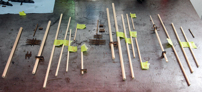
Nice progress, I like the bowsprit I always felt mine didn't look quite right and the masts only needed 3 sections. As all my parts where made I decided to go with plan.I decided the next project I would start is to build the masts. I first went in and cut the mid and upper mast sections and yard arms to the length shown on one of the full sized plans Between the first pole and the 3rd pole most of the diameters for the spars etc are listed in a table in the front of the manual. I wasn’t really happy with some of the diameters and changed a couple out with dowels a couple mm’s thicker. I had a lot of the thicker dowels left over. I popped out and trimmed the laser cut parts for the third pole and put them together.
View attachment 244877
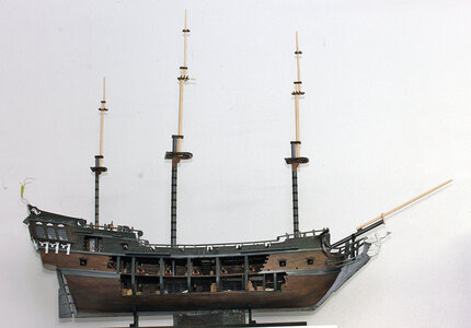
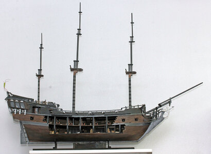
Here I spent quite a bit of time looking at the plans and the photos in the manual. One thing that struck me as odd was the ratio of the bow sprit to the masts. The bow sprit looks stubby and kind of naked. And the masts seem disproportionately tall. After looking a little closer I realized that there was an extra section on both the fore and main mast. While it’s not unusual to see a mast tree above the top sail on a mast, I don’t ever remember seeing a mast cap and an entire extra section of mast above the top sail. It probably exists somewhere but not on the ships I have. I think ZHL got carried away trying to add some more interest and made the mast an extra section too complicated. I say too complicated instead of too tall because I think the mast should be taller than where the upper mast cap is in the instructions but not as tall as it is on the plans. I also think the center section of the masts seemed out of proportion. So I made the center section of the fore and main masts an inch shorter than the plans and also made the top section an inch shorter than the plan shows for the top two sections.
Then while I was at it I cut the stubby looking bow sprit back and added another section so it’s about 4 inches longer than the plans show. Here is how the proportions look now. None of the masts are glued in or completely glued together in this photo, so don’t panic about them not being quite straight.
View attachment 244879
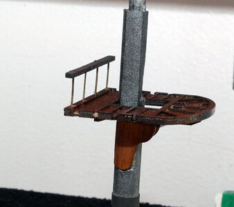
My next mission was to add the rails to the rear of the lower platforms. For the Fore Mast and Main Mast I used the tall eyelets included in the kit and first pin drilled the holes, then glued the wires in. The next morning I cut the excess off of both the top and the bottom. The photo below is of the Main Mast.
View attachment 244881
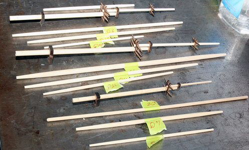
Then I went to work tapering and assembling the yard arms and upper mast sections. I would explain how I did it but I’m pretty sure that would facilitate a visit from OSHA. It involved multiple power tools used in other than intended ways, but other than sanding the skin off of one knuckle, no monkeys were harmed in making these parts.
View attachment 244882
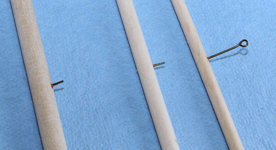
Next up I found the center of the yard arms and pinned them for the mast. Every square rigger ship model I’ve built shows the yards just being tied to the mast. I find it much easier to pin it in and then add the rope and blocks to make it look tied on. One again I used the long eyebolts and just cut pices to length after glueing them in.
View attachment 244883
Now while I was at it I made a sprit boom. I don’t plan on adding a sail here it’s main purpose is to make the bow sprit look more supported and complex instead of just having a single boom sticking out. Before putting it on I also added some eyelets across the top to hold the rigging. You can also see eye bolts added to the front of the catheads.
View attachment 244884
Then I painted the upper potions of the masts. These are still not glued in but here’s a good idea of how they’re looking.
View attachment 244886
