That’s pretty fast work, Jodie!I think this is pretty much ready for the next deck to be attached above. Before I do that I wanted to consider maybe adding a few more items, and also figure out what I need to do with the wires going to the back lantern. I decided this would be one of those place I should stop and think about it a bit before I close it up.
View attachment 218776
View attachment 218777
So I mounted the aft deck which shows how far off the front of the captain’s cabin is. I decided to just fix the small gaps instead of trying to adjust the completed work. I also drilled 3 holes in the deck to bring the wires for the rear lanterns through. I placed the upper side parts on temporarily to figure out where to drill the holes.
View attachment 218778
If I had seen this how these fit together before I built it I would have used the upper deck to shape the side pieces. Good tip for anyone building this kit that hasn’t gotten this far.
View attachment 218779
Here’s the port side with a filler piece and the last of the thin plywood pieces.
View attachment 218780
And the starboard side after filling it in and trimming the plywood to fit around it.
View attachment 218781
The next thing I needed to do was add the sides and stern above the captain’s cabin area. There are six parts in the photo below. The two thin plywood sides 2 sides made from walnut and the two aft pieces. I soaked the two stern pieces and arched them with a curling iron. My sides were closer together than the width across the new side walls. I used my disk sander to angle the ends of the back piece and make a angled notch on each side piece. Unfortunately I didn’t get a photo of that. Here’s all of the parts clamped in place.
View attachment 218782
View attachment 218783
In the photo below you can see the notch I cut in the top of the thicker side piece for the back part to set into. After this dried I drilled three holes through the top aft walnut piece for the magnet wires going to the three lanterns on the rear. The photos in the manual are pretty comical in relation to figuring out how these should be routed. There are photos where they look like they go to the rear, and even one where it appears the upper deck is in place and planked but the wires look like they are going through the front of the cabin. This arrangement made sense to me so I went with it.
View attachment 218784
Here’s another good tip if you haven’t gotten this far. The arched pieces in the photo below are grouped together, there are about 8 of them. The manual shows them in place with a bunch of filler plastered on them. I thought the photo was just of a layer of planking. If I had realized these were in the kit I would have used them to bend the stern parts to a matching radius. As it is, I was pretty close but had to clamp them in. There is also a note in the manual that says to run the wires for the lanterns through the groove in the back of these parts. I think running the wires separate will make it easier to hook up the lanterns.
View attachment 218785
So I painted the outside black in preparation for the rest of the planking.
View attachment 218786
View attachment 218787
I got to the point above on a Friday night and kind of went planking crazy on Saturday and Sunday. I thought I had taken some photos before the point below but I guess I just got lost having so much fun I forgot about it.
I started staining the newly added planking and got it a lot darker than I had intended originally. After over doing about 5 percent of it I decided I couldn’t take it off so I just made the whole upper portion much darker. I really like the effect it came out with.
View attachment 218788
View attachment 218789
View attachment 218790
Hopefully I can get this thread caught up to where I'm at tomorrow.
-

Win a Free Custom Engraved Brass Coin!!!
As a way to introduce our brass coins to the community, we will raffle off a free coin during the month of August. Follow link ABOVE for instructions for entering.
-

PRE-ORDER SHIPS IN SCALE TODAY!
The beloved Ships in Scale Magazine is back and charting a new course for 2026!
Discover new skills, new techniques, and new inspirations in every issue.
NOTE THAT OUR FIRST ISSUE WILL BE JAN/FEB 2026
You are using an out of date browser. It may not display this or other websites correctly.
You should upgrade or use an alternative browser.
You should upgrade or use an alternative browser.
Black Pearl 1:50 ZHL
- Thread starter MystRacing
- Start date
- Watchers 29
-
- Tags
- black pearl zhl
Well done on your progress it's looking good. l thought the cabin on my BP (golden edition) was hard but this one looks a lot more difficult with the curved stern and extra details.I think this is pretty much ready for the next deck to be attached above. Before I do that I wanted to consider maybe adding a few more items, and also figure out what I need to do with the wires going to the back lantern. I decided this would be one of those place I should stop and think about it a bit before I close it up.
View attachment 218776
View attachment 218777
So I mounted the aft deck which shows how far off the front of the captain’s cabin is. I decided to just fix the small gaps instead of trying to adjust the completed work. I also drilled 3 holes in the deck to bring the wires for the rear lanterns through. I placed the upper side parts on temporarily to figure out where to drill the holes.
View attachment 218778
If I had seen this how these fit together before I built it I would have used the upper deck to shape the side pieces. Good tip for anyone building this kit that hasn’t gotten this far.
View attachment 218779
Here’s the port side with a filler piece and the last of the thin plywood pieces.
View attachment 218780
And the starboard side after filling it in and trimming the plywood to fit around it.
View attachment 218781
The next thing I needed to do was add the sides and stern above the captain’s cabin area. There are six parts in the photo below. The two thin plywood sides 2 sides made from walnut and the two aft pieces. I soaked the two stern pieces and arched them with a curling iron. My sides were closer together than the width across the new side walls. I used my disk sander to angle the ends of the back piece and make a angled notch on each side piece. Unfortunately I didn’t get a photo of that. Here’s all of the parts clamped in place.
View attachment 218782
View attachment 218783
In the photo below you can see the notch I cut in the top of the thicker side piece for the back part to set into. After this dried I drilled three holes through the top aft walnut piece for the magnet wires going to the three lanterns on the rear. The photos in the manual are pretty comical in relation to figuring out how these should be routed. There are photos where they look like they go to the rear, and even one where it appears the upper deck is in place and planked but the wires look like they are going through the front of the cabin. This arrangement made sense to me so I went with it.
View attachment 218784
Here’s another good tip if you haven’t gotten this far. The arched pieces in the photo below are grouped together, there are about 8 of them. The manual shows them in place with a bunch of filler plastered on them. I thought the photo was just of a layer of planking. If I had realized these were in the kit I would have used them to bend the stern parts to a matching radius. As it is, I was pretty close but had to clamp them in. There is also a note in the manual that says to run the wires for the lanterns through the groove in the back of these parts. I think running the wires separate will make it easier to hook up the lanterns.
View attachment 218785
So I painted the outside black in preparation for the rest of the planking.
View attachment 218786
View attachment 218787
I got to the point above on a Friday night and kind of went planking crazy on Saturday and Sunday. I thought I had taken some photos before the point below but I guess I just got lost having so much fun I forgot about it.
I started staining the newly added planking and got it a lot darker than I had intended originally. After over doing about 5 percent of it I decided I couldn’t take it off so I just made the whole upper portion much darker. I really like the effect it came out with.
View attachment 218788
View attachment 218789
View attachment 218790
Hopefully I can get this thread caught up to where I'm at tomorrow.
Over the next few days I got the planking on the aft deck done.
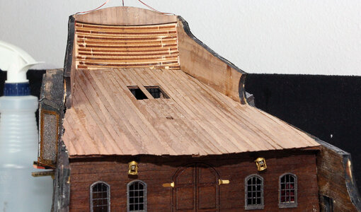
And then planked the sides and rear.
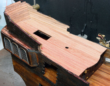
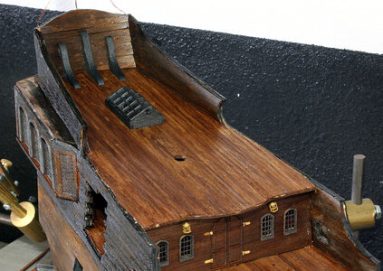
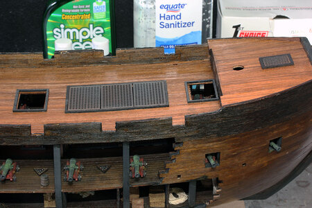
Next up was to trim the planking and put some finish on it. I also added the skylight on the rear and the frames around the holes in the deck. I did not add the rings that go around the bottom of the masts. I broke 1 but all of them were cut pretty uneven so decided I’d just do something similar to the wooldings when I build the masts. I used Creatix black pearl paint for the braces on the rear and the frames.
So my next mission was to do the roofs on the outside of the captain’s cabin. I have to confess rite up front that this wasn’t my idea. I saw this on someone else's build. I have no idea where that was.
The roof for this area is pretty much a scratch build project. The 1/2" (12mm) square stick of wood that is supplied in the kit might as well be a 2X4. They could have laser cut a stack of 4 or 5 pieces and then had us glue and sand them to shape which would be much easier. But that’s not what they did.
What I did was took a piece of molding I had leftover from a case I built that looked like this.
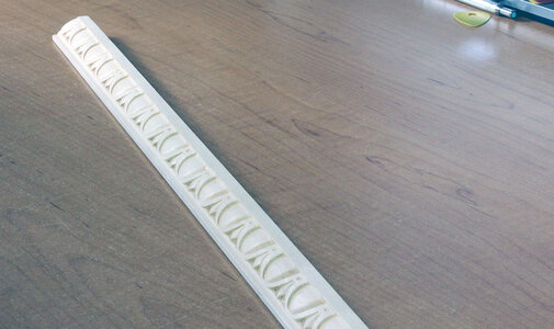
This was too tall and wide so I cut it down on my table saw to make it a better size for this project. I cut the angles on the front at 45 degrees, than cut the back of each side piece at 60 degrees, and the other 2 parts in the rear at 15 degrees. This created a part that was a full 180 degree figure.
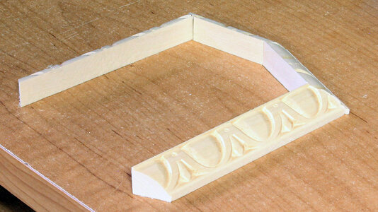
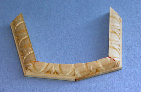
Of course the rear of the ship isn’t a nice square back end. I used my spindle sander to round the 2 back pieces then I used my little Proxxon disk sander to adjust the angles to make it fit the back of the ship. As I mentioned this is a scratch build thing I just eyeballed. I really don’t know how to help with that, it’s something you just have to play with. I also did a little hand carving around where the joints are to make the pattern kind of match up so the fact that it doesn’t wouldn’t be quite so obvious.
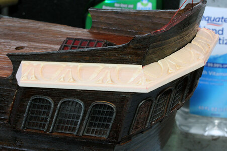
And here it is sitting on the back of the ship. I sanded the front of this piece to approximate the angle of the front of the side galleries. These are pretty different from one side to the other, but as any good custom pin striper will tell you you can’t see both sides at the same time!
And after a coat of black pearl paint and adding a little trim strip across the arched back here it is.
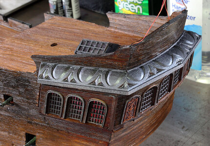
I did check the scroll work that goes on the back here and it’s tight but it will still fit. I should probably add another piece below to trim it underneath.
BP442
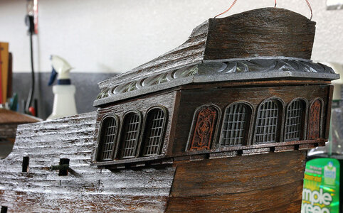
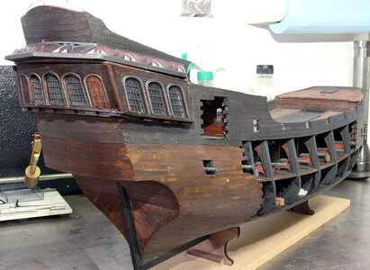
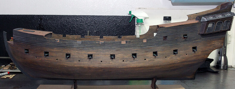
Next step was to airbrush the outside with a flat clear finish to get rid of the shine. These photos were taken in natural light and are very representative of how it looks in person.
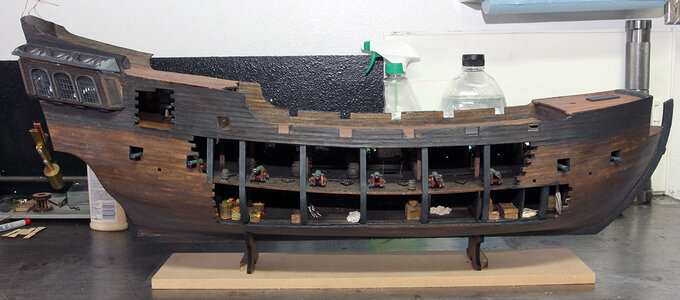
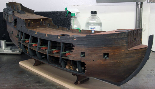

And then planked the sides and rear.

Next up was to trim the planking and put some finish on it. I also added the skylight on the rear and the frames around the holes in the deck. I did not add the rings that go around the bottom of the masts. I broke 1 but all of them were cut pretty uneven so decided I’d just do something similar to the wooldings when I build the masts. I used Creatix black pearl paint for the braces on the rear and the frames.


So my next mission was to do the roofs on the outside of the captain’s cabin. I have to confess rite up front that this wasn’t my idea. I saw this on someone else's build. I have no idea where that was.
The roof for this area is pretty much a scratch build project. The 1/2" (12mm) square stick of wood that is supplied in the kit might as well be a 2X4. They could have laser cut a stack of 4 or 5 pieces and then had us glue and sand them to shape which would be much easier. But that’s not what they did.
What I did was took a piece of molding I had leftover from a case I built that looked like this.

This was too tall and wide so I cut it down on my table saw to make it a better size for this project. I cut the angles on the front at 45 degrees, than cut the back of each side piece at 60 degrees, and the other 2 parts in the rear at 15 degrees. This created a part that was a full 180 degree figure.

Of course the rear of the ship isn’t a nice square back end. I used my spindle sander to round the 2 back pieces then I used my little Proxxon disk sander to adjust the angles to make it fit the back of the ship. As I mentioned this is a scratch build thing I just eyeballed. I really don’t know how to help with that, it’s something you just have to play with. I also did a little hand carving around where the joints are to make the pattern kind of match up so the fact that it doesn’t wouldn’t be quite so obvious.

And here it is sitting on the back of the ship. I sanded the front of this piece to approximate the angle of the front of the side galleries. These are pretty different from one side to the other, but as any good custom pin striper will tell you you can’t see both sides at the same time!

And after a coat of black pearl paint and adding a little trim strip across the arched back here it is.

I did check the scroll work that goes on the back here and it’s tight but it will still fit. I should probably add another piece below to trim it underneath.
BP442

Next step was to airbrush the outside with a flat clear finish to get rid of the shine. These photos were taken in natural light and are very representative of how it looks in person.


A lot more nicely done than my mangled stick! Very artistic.Over the next few days I got the planking on the aft deck done.
View attachment 219016
And then planked the sides and rear.
View attachment 219017
Next up was to trim the planking and put some finish on it. I also added the skylight on the rear and the frames around the holes in the deck. I did not add the rings that go around the bottom of the masts. I broke 1 but all of them were cut pretty uneven so decided I’d just do something similar to the wooldings when I build the masts. I used Creatix black pearl paint for the braces on the rear and the frames.
View attachment 219018
View attachment 219019
So my next mission was to do the roofs on the outside of the captain’s cabin. I have to confess rite up front that this wasn’t my idea. I saw this on someone else's build. I have no idea where that was.
The roof for this area is pretty much a scratch build project. The 1/2" (12mm) square stick of wood that is supplied in the kit might as well be a 2X4. They could have laser cut a stack of 4 or 5 pieces and then had us glue and sand them to shape which would be much easier. But that’s not what they did.
What I did was took a piece of molding I had leftover from a case I built that looked like this.
View attachment 219021
This was too tall and wide so I cut it down on my table saw to make it a better size for this project. I cut the angles on the front at 45 degrees, than cut the back of each side piece at 60 degrees, and the other 2 parts in the rear at 15 degrees. This created a part that was a full 180 degree figure.
View attachment 219022
Of course the rear of the ship isn’t a nice square back end. I used my spindle sander to round the 2 back pieces then I used my little Proxxon disk sander to adjust the angles to make it fit the back of the ship. As I mentioned this is a scratch build thing I just eyeballed. I really don’t know how to help with that, it’s something you just have to play with. I also did a little hand carving around where the joints are to make the pattern kind of match up so the fact that it doesn’t wouldn’t be quite so obvious.
View attachment 219023
And here it is sitting on the back of the ship. I sanded the front of this piece to approximate the angle of the front of the side galleries. These are pretty different from one side to the other, but as any good custom pin striper will tell you you can’t see both sides at the same time!
View attachment 219024
And after a coat of black pearl paint and adding a little trim strip across the arched back here it is.
View attachment 219025
I did check the scroll work that goes on the back here and it’s tight but it will still fit. I should probably add another piece below to trim it underneath.
BP442
View attachment 219026
Next step was to airbrush the outside with a flat clear finish to get rid of the shine. These photos were taken in natural light and are very representative of how it looks in person.
View attachment 219027
View attachment 219028
View attachment 219029
View attachment 219030
It also hides some of the overlapping edges. I probably should have done more sanding on my galleys.
She's looking good !
I will be starting this model in a few weeks.
I also plan to paint the timbers black, I was thinking of dying the sails a charcoal grey?
I will be starting this model in a few weeks.
I also plan to paint the timbers black, I was thinking of dying the sails a charcoal grey?
I thought about that too, but the recipient wanted more natural looking sails with tea dyed look. I also thought too much black and gray would make the overall appearance dull and the details would be lost without some contrasts. So the sails are as they are with tea stains.She's looking good !
I will be starting this model in a few weeks.
I also plan to paint the timbers black, I was thinking of dying the sails a charcoal grey?
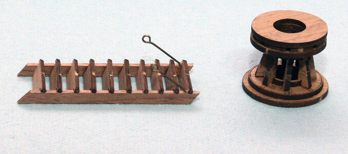
So up next were the last few parts in the first section of the manual. I built the capstan but didn’t want to glue it on yet and I went to work on the staircase to the main deck. I did stain and install the staircase but didn’t take a picture of it yet.
Edit: when I got to the point of working on the masts I had already assembled the capstan including the chains around it etc. When I tried to slide it on the mast it got stuck and by the time I got it off I had about 10 pieces. I would recommend not doing anything with the capstan until you're prepping the masts to be mounted. Then build it around the mast at that time.
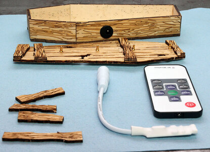
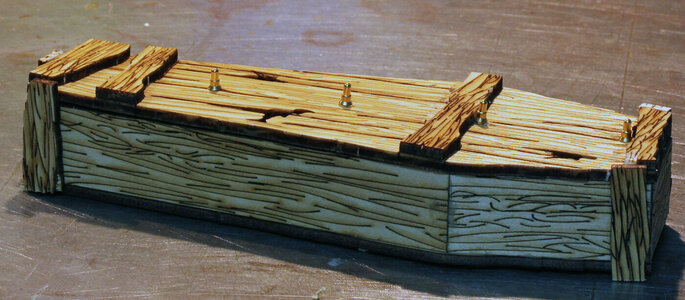
The last part in the first book is the power for the lighting. I assembled the coffin the lights go in. The bottom part is pretty self explanatory. The lid has to be drilled with a 2.5mm bit to accept the spring loaded brass pins. These 4 pins will match up with the brass strips on the bottom of the keel. You can also see the controller and the remote.
The next step is to remove the heat shrink from the circuit board. I chose to cut it rite down the side of the board to hopefully not damage any components.
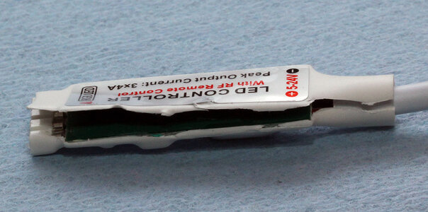
Here it is after stripping the heat shrink and cover from the wiring.
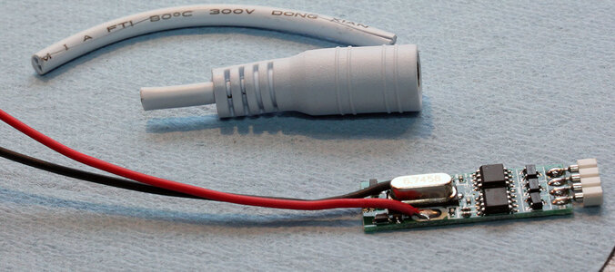
You then have to unsolder the connector on the end of the circuit board and solder magnet wire to the board in its place. I can’t help but think for a few pennies they could have just included a matching connector so you wouldn’t have to do the soldering on the board. For a buck or two maybe even just provide a connecter with everything hooked up. At any rate here it is all rewired.
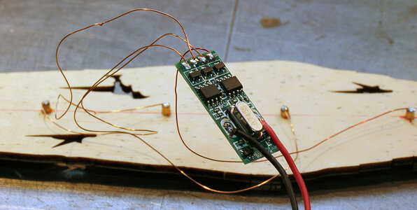
Here you can see all the parts, and from the outside.
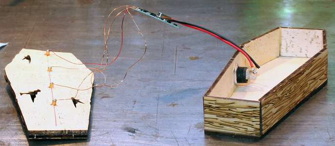
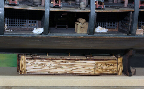
Here is the coffin in place under the keel you can see where the contacts touch the bottom of the ship. This all seems over complicated to me to be honest. The controller is for doing all kinds of flashing effects etc when all that seems really necessary is a on off switch.
And here’s where I was planning on putting a photo of it all lit up. However; there was something wrong with the controller or the remote. When I plug it in it flashes the three sections of lights alternately at a pretty high speed. The remote control won’t do anything. One odd thing is the controller had one of those plastic tabs to keep a battery from draining, but there was no battery in it. I put in a brand new buttery but still no response. I sent an e-mail to ZHL so hopefully I’ll get a response as to if I’m doing something wrong or if I have a defective part.
This problem was solved as I'm actually quite a ways ahead of this post so there's no need for suggestions about the lights. After several e-mails back and forth with Max at ZHL the language barrier was too much to overcome. I kept telling him the remote wouldn’t work, but kept getting responses like you need a battery in it, or flashing is a mode. I figured worst case I could always just get a wall wart of the proper voltage and hook it to a switch. Then it donned on me that I have friends in high places. So I asked Victator @Vfordyce if he still had his controller because I knew he was using different leds and sure enough he hooked me up and sent me his controller. That fixed my problems so now the lights work correctly. I’ll get some photos up with the lights on in the near future.
Edit: when I got to the point of working on the masts I had already assembled the capstan including the chains around it etc. When I tried to slide it on the mast it got stuck and by the time I got it off I had about 10 pieces. I would recommend not doing anything with the capstan until you're prepping the masts to be mounted. Then build it around the mast at that time.

The last part in the first book is the power for the lighting. I assembled the coffin the lights go in. The bottom part is pretty self explanatory. The lid has to be drilled with a 2.5mm bit to accept the spring loaded brass pins. These 4 pins will match up with the brass strips on the bottom of the keel. You can also see the controller and the remote.

The next step is to remove the heat shrink from the circuit board. I chose to cut it rite down the side of the board to hopefully not damage any components.

Here it is after stripping the heat shrink and cover from the wiring.

You then have to unsolder the connector on the end of the circuit board and solder magnet wire to the board in its place. I can’t help but think for a few pennies they could have just included a matching connector so you wouldn’t have to do the soldering on the board. For a buck or two maybe even just provide a connecter with everything hooked up. At any rate here it is all rewired.

Here you can see all the parts, and from the outside.


Here is the coffin in place under the keel you can see where the contacts touch the bottom of the ship. This all seems over complicated to me to be honest. The controller is for doing all kinds of flashing effects etc when all that seems really necessary is a on off switch.

And here’s where I was planning on putting a photo of it all lit up. However; there was something wrong with the controller or the remote. When I plug it in it flashes the three sections of lights alternately at a pretty high speed. The remote control won’t do anything. One odd thing is the controller had one of those plastic tabs to keep a battery from draining, but there was no battery in it. I put in a brand new buttery but still no response. I sent an e-mail to ZHL so hopefully I’ll get a response as to if I’m doing something wrong or if I have a defective part.
This problem was solved as I'm actually quite a ways ahead of this post so there's no need for suggestions about the lights. After several e-mails back and forth with Max at ZHL the language barrier was too much to overcome. I kept telling him the remote wouldn’t work, but kept getting responses like you need a battery in it, or flashing is a mode. I figured worst case I could always just get a wall wart of the proper voltage and hook it to a switch. Then it donned on me that I have friends in high places. So I asked Victator @Vfordyce if he still had his controller because I knew he was using different leds and sure enough he hooked me up and sent me his controller. That fixed my problems so now the lights work correctly. I’ll get some photos up with the lights on in the near future.
Last edited:
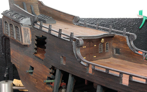
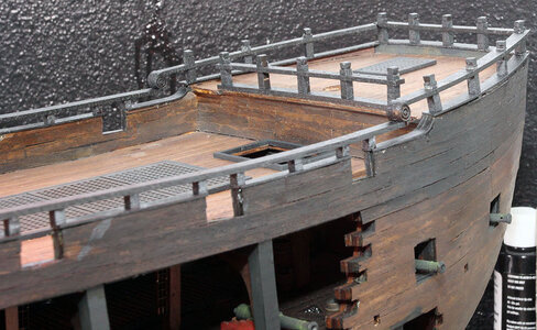
So while waiting for the remote issue to be solved I went ahead and moved forward with the installation of the railings on the edge of the deck. I don’t really have much to say here tip wise, other than what Vic mentioned in his thread, if you’re going to paint the railings it’s definitely easier to paint the parts before assembling them on the ship. There are a lot of parts making up the rails so definitely take some time and make sure you’re using the correct ones. Here’s the end result.
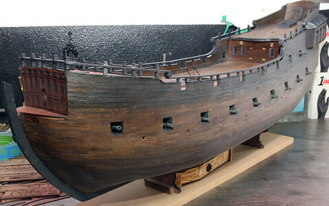
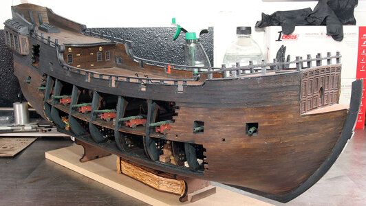
I next decided to glue the forward part of the keel on. I knocked it off while working on the next step and then re-glued it. It would probably be best to wait till you are ready to glue a couple of the side supports on this part before attaching this piece. But it’s on now.
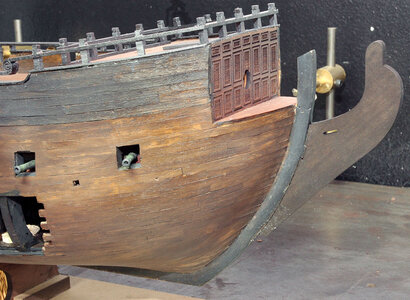


I next decided to glue the forward part of the keel on. I knocked it off while working on the next step and then re-glued it. It would probably be best to wait till you are ready to glue a couple of the side supports on this part before attaching this piece. But it’s on now.

My next project was to put the whales on. This is something else that is really ambiguous in the instructions. Both where they go, and when to put them on. I looked back and forth in the second pole manual and there really isn’t a step stating to put these on. They are shown in step one but it’s not so much instruction as a diagram.
At any rate the large plan sheet number one is where I went to make my best guess where to put them. The lower pair are relatively self explanatory after looking a bit. The upper one goes just under the sweep ports on the side of the ship. The one that runs between the upper and lower gun ports isn’t so clear. I measured off the plan and compared that to the side of the ship. I finally settled on running the whale on top of the 5th plank down from the rail. This actually matched up with being the first plank above where I started planking on post #76. This makes the whale actually match with the main deck which is very common.
However; there was one minor problem, on the open side of the ship there was nothing but air in this location. My solution was to add one plank on the upper side of the opening. Just by luck one of the 5mm by 2mm planks fit right in. Here’s a photo of it clamped in place drying. Hindsight being 20/20 if you’re going with this location it would be good to go ahead and plank this run back at the appropriate time.
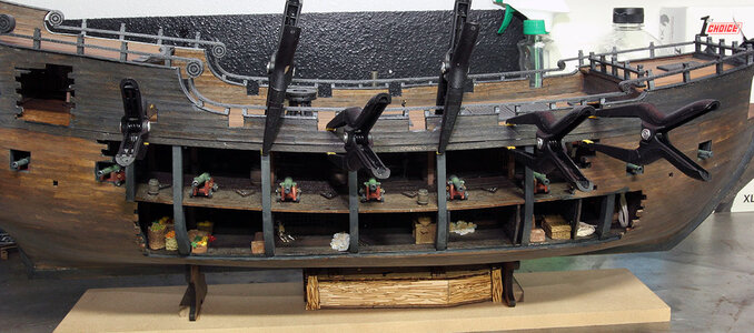
One could argue this is the wrong location and the whale should be moved up one plank. In my case I like the way it acts as a separator between the lighter and darker sections of planking so I’m very much happy with it. That’s just my preference of course. There is however another issue. If you look at the opening going into the captain’s cabin if you move the whale up it’ll cross in front of the lower portion of the opening, or you can cut it and be on each side. Whatever you prefer. I’m going to add a tip back at post #76 for people to read this post to better decide the whale location. Here’s the port side.
The final piece is the one that goes from the stern gallery along the poop deck. On the port side this could go anywhere along the side in this area. I measured the plan again and got all prepared to attach it when it occurred to me it should be in the same location on each side. Once again there is another issue. On the starboard side the opening for the captain’s cabin extends all the way up to 2 plank widths from the bottom of the rail. If the whale is located that high up there isn’t room for the boards the shrouds attach too. So I filled in the top and ran the whale across what would be the 4th plank down.
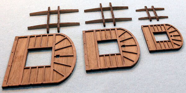
EDIT: Somewhere around this point you'll start using the second box extensively. I would recommend that you take the frames that fit on the lower platforms and glue them on about now. By the time I got to where they told me to do it in the instructions mine were pretty busted up from months of foreaging around in the box. Or maybe just take that laser cut sheet out and put it somewhere safe. This is what I'm talking about.
At any rate the large plan sheet number one is where I went to make my best guess where to put them. The lower pair are relatively self explanatory after looking a bit. The upper one goes just under the sweep ports on the side of the ship. The one that runs between the upper and lower gun ports isn’t so clear. I measured off the plan and compared that to the side of the ship. I finally settled on running the whale on top of the 5th plank down from the rail. This actually matched up with being the first plank above where I started planking on post #76. This makes the whale actually match with the main deck which is very common.
However; there was one minor problem, on the open side of the ship there was nothing but air in this location. My solution was to add one plank on the upper side of the opening. Just by luck one of the 5mm by 2mm planks fit right in. Here’s a photo of it clamped in place drying. Hindsight being 20/20 if you’re going with this location it would be good to go ahead and plank this run back at the appropriate time.

One could argue this is the wrong location and the whale should be moved up one plank. In my case I like the way it acts as a separator between the lighter and darker sections of planking so I’m very much happy with it. That’s just my preference of course. There is however another issue. If you look at the opening going into the captain’s cabin if you move the whale up it’ll cross in front of the lower portion of the opening, or you can cut it and be on each side. Whatever you prefer. I’m going to add a tip back at post #76 for people to read this post to better decide the whale location. Here’s the port side.

The final piece is the one that goes from the stern gallery along the poop deck. On the port side this could go anywhere along the side in this area. I measured the plan again and got all prepared to attach it when it occurred to me it should be in the same location on each side. Once again there is another issue. On the starboard side the opening for the captain’s cabin extends all the way up to 2 plank widths from the bottom of the rail. If the whale is located that high up there isn’t room for the boards the shrouds attach too. So I filled in the top and ran the whale across what would be the 4th plank down.

EDIT: Somewhere around this point you'll start using the second box extensively. I would recommend that you take the frames that fit on the lower platforms and glue them on about now. By the time I got to where they told me to do it in the instructions mine were pretty busted up from months of foreaging around in the box. Or maybe just take that laser cut sheet out and put it somewhere safe. This is what I'm talking about.

Last edited:
- Joined
- Mar 1, 2021
- Messages
- 315
- Points
- 168

Jodie I greatly appreciate your explanation of this process...so after all the mumbo-jumbo with Max it ended up being a defective remote? I agree, to have to strip out the heat shrink and unsolder the connector seems a bit too Chinese for a $500 kit! ZHL should fix this for future kits as an updated version! I ordered lights from Evan Designs and decided to go 3v with remote an AC adapter....but then I was a bit pissed to spend an extra $100 to simplify the wiring so I decided to see if I could solder the kit LED’s anyway! Please permit me to PM you if I run into any problem once I reach this stage! Again, great work and I have learned much from you and your build thread! I glued in my lower deck this morning....like handling a brittle, curled potato chip. However, your advice to take the time to square things made it easy for me...I ran a dremel very lightly around the rib slots and worked it in very carefully...all good! Put a lot of weight on it. Tomorrow morning I hope to see my deck is flat and secure!So up next were the last few parts in the first section of the manual. I built the capstan but didn’t want to glue it on yet and I went to work on the staircase to the main deck. I did stain and install the staircase but didn’t take a picture of it yet.
View attachment 224371
The last part in the first book is the power for the lighting. I assembled the coffin the lights go in. The bottom part is pretty self explanatory. The lid has to be drilled with a 2.5mm bit to accept the spring loaded brass pins. These 4 pins will match up with the brass strips on the bottom of the keel. You can also see the controller and the remote.
View attachment 224372
The next step is to remove the heat shrink from the circuit board. I chose to cut it rite down the side of the board to hopefully not damage any components.
View attachment 224373
Here it is after stripping the heat shrink and cover from the wiring.
View attachment 224374
You then have to unsolder the connector on the end of the circuit board and solder magnet wire to the board in its place. I can’t help but think for a few pennies they could have just included a matching connector so you wouldn’t have to do the soldering on the board. For a buck or two maybe even just provide a connecter with everything hooked up. At any rate here it is all rewired.
View attachment 224375
Here you can see all the parts, and from the outside.
View attachment 224376
View attachment 224377
Here is the coffin in place under the keel you can see where the contacts touch the bottom of the ship. This all seems over complicated to me to be honest. The controller is for doing all kinds of flashing effects etc when all that seems really necessary is a on off switch.
View attachment 224378
And here’s where I was planning on putting a photo of it all lit up. However; there was something wrong with the controller or the remote. When I plug it in it flashes the three sections of lights alternately at a pretty high speed. The remote control won’t do anything. One odd thing is the controller had one of those plastic tabs to keep a battery from draining, but there was no battery in it. I put in a brand new buttery but still no response. I sent an e-mail to ZHL so hopefully I’ll get a response as to if I’m doing something wrong or if I have a defective part.
This problem was solved as I'm actually quite a ways ahead of this post so there's no need for suggestions about the lights. After several e-mails back and forth with Max at ZHL the language barrier was too much to overcome. I kept telling him the remote wouldn’t work, but kept getting responses like you need a battery in it, or flashing is a mode. I figured worst case I could always just get a wall wart of the proper voltage and hook it to a switch. Then it donned on me that I have friends in high places. So I asked Victator @vdforce if he still had his controller because I knew he was using different leds and sure enough he hooked me up and sent me his controller. That fixed my problems so now the lights work correctly. I’ll get some photos up with the lights on in the near future.
Ahoy mate!
Rick
Last edited:
With the captain’s cabin opening, the placement of the wales is a bit more of an issue. I think I spaced my lower two Wales too far apart. And the front starboard Wales were a guess as to where to place them. I didn’t like my end product there.My next project was to put the whales on. This is something else that is really ambiguous in the instructions. Both where they go, and when to put them on. I looked back and forth in the second pole manual and there really isn’t a step stating to put these on. They are shown in step one but it’s not so much instruction as a diagram.
At any rate the large plan sheet number one is where I went to make my best guess where to put them. The lower pair are relatively self explanatory after looking a bit. The upper one goes just under the sweep ports on the side of the ship. The one that runs between the upper and lower gun ports isn’t so clear. I measured off the plan and compared that to the side of the ship. I finally settled on running the whale on top of the 5th plank down from the rail. This actually matched up with being the first plank above where I started planking on post #76. This makes the whale actually match with the main deck which is very common.
However; there was one minor problem, on the open side of the ship there was nothing but air in this location. My solution was to add one plank on the upper side of the opening. Just by luck one of the 5mm by 2mm planks fit right in. Here’s a photo of it clamped in place drying. Hindsight being 20/20 if you’re going with this location it would be good to go ahead and plank this run back at the appropriate time.
View attachment 224384
One could argue this is the wrong location and the whale should be moved up one plank. In my case I like the way it acts as a separator between the lighter and darker sections of planking so I’m very much happy with it. That’s just my preference of course. There is however another issue. If you look at the opening going into the captain’s cabin if you move the whale up it’ll cross in front of the lower portion of the opening, or you can cut it and be on each side. Whatever you prefer. I’m going to add a tip back at post #76 for people to read this post to better decide the whale location. Here’s the port side.
View attachment 224385
The final piece is the one that goes from the stern gallery along the poop deck. On the port side this could go anywhere along the side in this area. I measured the plan again and got all prepared to attach it when it occurred to me it should be in the same location on each side. Once again there is another issue. On the starboard side the opening for the captain’s cabin extends all the way up to 2 plank widths from the bottom of the rail. If the whale is located that high up there isn’t room for the boards the shrouds attach too. So I filled in the top and ran the whale across what would be the 4th plank down.
View attachment 224386
Rick,
Feel free to PM me. Happy to pass on what I know. I love your build log BTW, you must look up the phrase "You'll have the Devil to pay" by far my favorite nautical term.
Thanks for the compliments too. I was pretty happy I put in the effort to build it square when I started putting the railings on it made them fit real nice.
What good progress you have made I especially like the different colour schemes on the BPs. They all come out looking good but quite different. Keep up the good work.
Tony
Tony
- Joined
- Mar 1, 2021
- Messages
- 315
- Points
- 168

Jodie I believe I’ll be running into the same problem you experienced with the second deck being too tight in the stern. I estimate 2-3mm needs to be cut further back into the deck...the top deck fits fine and I used it like you did to set the starboard bulkheads...after they dried the top deck came out no problem...so before gluing the 5 stems to the keel, I wanted to see if the 2nd deck would fit...nope! I don’t think we shortened up the keel when we glued it together, because I remember your thread and I purposely didn’t tighten it up when I glued them together...ZHL needs to reprogram their laser saw to allow a longer keel..In reference to decorating this lower deck there are tons of improvements that could be made. Some I think might be worth it others probably not. As mentioned above the bars could be centered in the partitions, or maybe even better walls could be built to sandwich the bars which would look far better. I considered putting a groove in the top of the beams where the gun deck attaches and run the wires basically on top of the beam to hide them under the above deck. IMO it comes down to what your goal is and how much time you want to spend on it. I doubt anyone who actually sees this model in person will look close enough to see the wires that are painted black running along the roof or notice the bars aren’t centered in the walls. But it’s something to think about.
I also put some consideration into the possibility of making it more true to what an actual ship might have in it. There is no were to cook in this thing. At the same time I doubt anyone will ever look at this model and seriously critique the accuracy.
So I got back to work on this after a bit of a break and the first thing I discovered was I made a mistake. Parts E1 and E2 are fore and aft walnut bulkheads that need to be added. The rear bulkhead needs to be installed before the hangers for the lanterns. I edited the earlier posts to reflect this.
View attachment 179624
I did some sanding on the deck to give it more of a warn appearance.
View attachment 179625
Next up was the decorations for the lower deck. There are two piles of skeletons. They have a bottom that is about 1/16th of an inch thick and it needs to be sanded off. It’s pretty easy to do with a rotary tool and sanding drum as shown in the instructions. I also cut out the single skeleton and painted it all white.
View attachment 179626
Then it was painting bottles and miscellaneous boxes etc. Here is what I came up with.
View attachment 179627
View attachment 179628
I also created this little carpenters table by cutting the top off of one of the fruit and vegetable stand decorations and adding some small barrels below it for legs.
View attachment 179629
That's good to know. My trimming the notch a few mm's deeper didn't cause any problems. I'll go back and edit this thread to say that it's a flaw in how the deck or keel is cut so others know. I think it's the deck but it's hard to tell. I didn't have any obvious issues with my length on the rest of the parts. It's kind of hard to tell where the inaccuracies are by the time you get to the captain's cabin and above because there are so many parts that could be slightly off, but I didn't have any places where it was off by enough to claim it wasn't just build tolerances, aside from that notch.
My next project was to put the whales on. This is something else that is really ambiguous in the instructions. Both where they go, and when to put them on. I looked back and forth in the second pole manual and there really isn’t a step stating to put these on. They are shown in step one but it’s not so much instruction as a diagram.
At any rate the large plan sheet number one is where I went to make my best guess where to put them. The lower pair are relatively self explanatory after looking a bit. The upper one goes just under the sweep ports on the side of the ship. The one that runs between the upper and lower gun ports isn’t so clear. I measured off the plan and compared that to the side of the ship. I finally settled on running the whale on top of the 5th plank down from the rail. This actually matched up with being the first plank above where I started planking on post #76. This makes the whale actually match with the main deck which is very common.
However; there was one minor problem, on the open side of the ship there was nothing but air in this location. My solution was to add one plank on the upper side of the opening. Just by luck one of the 5mm by 2mm planks fit right in. Here’s a photo of it clamped in place drying. Hindsight being 20/20 if you’re going with this location it would be good to go ahead and plank this run back at the appropriate time.
View attachment 224384
One could argue this is the wrong location and the whale should be moved up one plank. In my case I like the way it acts as a separator between the lighter and darker sections of planking so I’m very much happy with it. That’s just my preference of course. There is however another issue. If you look at the opening going into the captain’s cabin if you move the whale up it’ll cross in front of the lower portion of the opening, or you can cut it and be on each side. Whatever you prefer. I’m going to add a tip back at post #76 for people to read this post to better decide the whale location. Here’s the port side.
View attachment 224385
The final piece is the one that goes from the stern gallery along the poop deck. On the port side this could go anywhere along the side in this area. I measured the plan again and got all prepared to attach it when it occurred to me it should be in the same location on each side. Once again there is another issue. On the starboard side the opening for the captain’s cabin extends all the way up to 2 plank widths from the bottom of the rail. If the whale is located that high up there isn’t room for the boards the shrouds attach too. So I filled in the top and ran the whale across what would be the 4th plank down.
View attachment 224386
Great advice on fixing an issue however I don't seem to follow what's happening, that's my problem.
I'll come back to this when I get closer to installing it.
Overall, it sounds like I should install the whales lower than the kit specifies.
Great advice on fixing an issue however I don't seem to follow what's happening, that's my problem.
I'll come back to this when I get closer to installing it.
Overall, it sounds like I should install the whales lower than the kit specifies.
Rowboat,
Not necessarily. The two lower ones are just below the sweep ports like the plan shows. Though mine are spaced 5mm's apart and the plans are a little further. The upper is basically along the main deck line and could be up of down a plank from the main deck and it probably doesn't matter. The ones by the stern gallery are the issue because of the size of the cutout for the captains cabin. Wehn you get there you'll figure it out.
It wasn't an issue for me because I neglected to do the cutout. I found the open area on the starboard side to be a challenge because I wasn't able to continue the wale all the way across. I got a little too much curve in it, as a result. I guess precision does pay off in the long run. She's looking good, Jodie!
I’ve slowed down on working on this a bit. It’s spring in Western Colorado and spring is the time of year I have the least amount of hobby time. On top of the usual spring stuff like the yard etc. we’ve been camping already and have travels as well. Still I have been getting a little done.
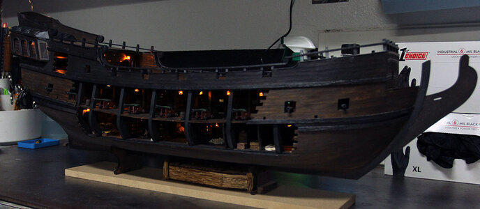
I received the remote from Vic as I mentioned earlier, so finally here’s some pictures with the lights on. Thanks again to Vic.
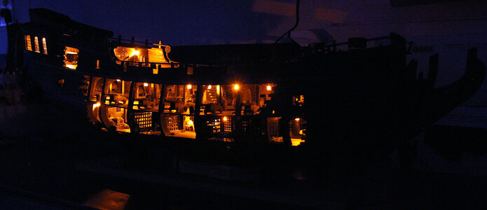
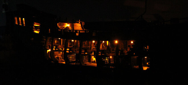
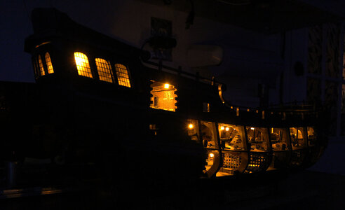
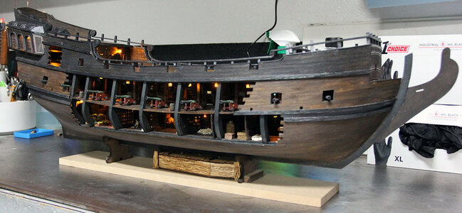
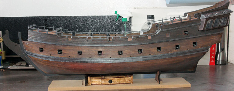
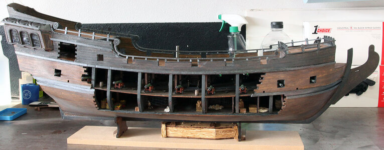
I decided at this point it was time to upgrade the firepower a bit.
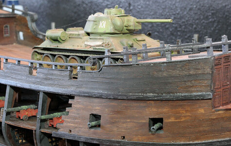
That is obviously a joke. I painted the base black and stained the coffin with the black stain to make it go with the ship.
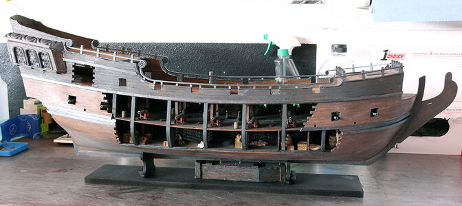
Next time to get to work on the main deck.
I received the remote from Vic as I mentioned earlier, so finally here’s some pictures with the lights on. Thanks again to Vic.


I decided at this point it was time to upgrade the firepower a bit.

That is obviously a joke. I painted the base black and stained the coffin with the black stain to make it go with the ship.

Next time to get to work on the main deck.


