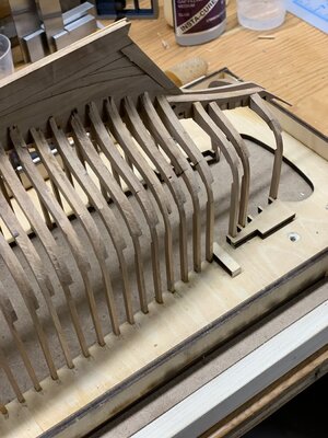
Bluenose build - DaveFx35

OK,I am curious what the two paddle shaped devices aft of the forward frames are. . . look like spacing and support implements on long rods supported and held by something else. I apologize for not being in the build phase here but just presently watching learning what I can and not stressing about forgetting a lot before I am actively engaged. Rich
They are just clamps to insure that the frames are held in the jig properly
 
Somewhat of a milestone reached.
Completed the framing up to the transom frames.
Hands are very sore from filing, sanding and general abuse!
IMG-0338.jpg

IMG-0339.jpg

Had to do some fairing up of the internal framing in preparation for the keelson and internal beam work.
I had some unevenness due to not paying close enough attention during frame insertion.
I can speak from experience, pay attention here.

I ended up doing most of the frame insertion from the side and only came in from the top when I got towards the transom

IMG-0341.jpg

I don't remember who's post suggested these dense foam sanding blocks, but they work pretty well.
I still had problems given the thin nature of the hull.
They weren't cheap but are pretty useful.
https://www.eastwood.com/soft-sande...-WQCFerNELVhP4gVaOHSoOmOUi2PcathoCRIkQAvD_BwE


IMG-0342.jpg

IMG-0343.jpg

Working on the transom frames and should have another update soon.

Dave
 
Heinrich,

While starting the transom framing I realized that I had an alignment issue.
Wondering if you have a color image of this area.
From an earlier image, the transom support is misaligned with frame 50.
IMG-0331.jpg

I decided to disassemble frames 46-50 (they weren't fully seated in the keel) and the two transom supports.
I found that using vinegar will eventually dissolve Titebond II
Use it carefully as it discolors the wood slightly. I also flushed it with water after the bond separated.
I'll see how it cleans up after thoroughly drying.
IMG-0344.jpg


After drying:

IMG-0350.jpg

The bottom of the transom looks like it fairs with the bottom of frame 50
IMG-0353.jpg
 

Attachments

  • IMG-0349.jpg
    IMG-0349.jpg
    229 KB · Views: 12
I've waxed the area below the deck beam clamps. They will not be easy to get at after the deck beams are installed. It's hard to see the finish in the photos.
For comparison the transom framing hasn't been waxed yet.

IMG-0368.jpgIMG-0370.jpg

I've been looking at the placement of the deck beams and could use some help here.
The image below shows the first deck beam between the first and second frames
Are all beams placed between frames or is there some other frame spacing? It's not clear from any images I've seen as it would need to show a view from directly overhead.
I've looked at Eric's build which looks like its aligned with the back of the preceding frame but couldn't really tell.
I've even looked at the Eisnor plans and Bodner builds and can't see a relationship between the deck beams and the frames.
Based on Gene Bodner's practicum (http://modelshipbuilder.com/e107_im...eisnor/bn-1-4/Bluenose Practicum Standard.pdf starting on page 60) it seems that they are independent of each other.
Any help would be appreciated.

Can we get a translation to English of page 15?

Dave


IMG-0371.jpg
 
The only answer I could give is what I did and that was to use the deck parts and see how it lines up.
Mine was way off on the first try.
I don’t know if I did something wrong or not.
 
Terry,
I've been pretty preoccupied with my own build and missed your journey through this.
Now that I've looked at your build, I'm thankful that you shared this.
It didn't occur to me to use the deck planking piece as an alignment tool.
This has been immensely helpful and has helped me avoid a lot of rework!
I know that it's a little painful to share mistakes as well as successes, but what a great tool for all of us.
Dave
 
Some progress to report.
Deck beam work nearing completion.
Fingers are pretty sore from sanding small pieces. I'm starting to get blood spots on parts.
Time to call it a day!
Will be sanding the deck tomorrow.
The transom area area is in need of some surgical repair.

IMG-0386.jpgIMG-0388.jpg
IMG-0387.jpg

An interesting view of the hull slung beneath the jig.

IMG-0389.jpg
Dave
 

Attachments

  • IMG-0391.jpg
    IMG-0391.jpg
    205.2 KB · Views: 11
Back
Top