Build Log: CAF models' HMS Enterprise 1:48

Thank you very much Tom. This will be very helpful when I build the jig.
However, by my own mistake, I did not construct frames 08 and 09 correctly, (please see my my Enterprise build where I explain it and the new method I am using to make the frames), although I can sand them down and alleviate the problem.
However, ideally, I would like to see if I can obtain from you frame sheets number 01 and 02 in cherrywood (box # 1) containing the parts (futtocks) for frames number 08 and 09 so I can re-make them in the correct fashion. I would like to buy these from you plus shipping cost. My e-mail is alrosase@gmail.com. Let me know if this is possible.
Alex Rosas
 
Progress report on frame building. I initially built frames number 08 and 09 as described in my initial post. However, the more I thought about it, this did not seem to be the correct way. The half frames were not in complete alignment, since the "A" frame was glued onto the interior bevel line of the "B" frame. I realized that when it came time to cut the bevel, it would not work. It is probably written in Chinese in the instructions, but I certainly could not figure it out. After a lot of thinking, I figured out how to do it correctly (I think)...Iimagine some of you are saying: "of course" what an idiot" doesn't he know how to build a frame " Well maybe not....Anyway, enough of this, here is the way I am making the frames now:
1) First, I lightly sand the BACKSIDE of the wood with the laser-cut futtocks to get rid of laser char and surface irregularities , since the half frames will be glued back to back...
2)The half-frame that has the bevel line lasered on the inboard or interior side of the frame ( frame made up of pieces "B" in a double frame, and pieces "C" in a triple frame) is attached with UHU glue to the plan tracing FACE DOWN, that is, it will be facing towards the stern. The pieces are joined end-to end with wood flue. I have also started to use pins stuck to the foam board to limit movement. You will now have the backside of frame "B" facing you.
3)The pieces fo frame "A" are attached with wood glue on top of the backside of frame "B"
4) Now you will have the front side, i.e, the one with the laser bevel and/or number printed on it, facing you.
5) I put a little jig in place on the keel notch of the center futtocks to keep them aligned. It kinda looks like an "arc de Triumph" see my picture.
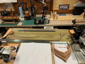
6) After putting the frame under plate glass for several hours, the backside of frame "B" easily separates from the tracing paper with the frame outline. Now you have a perfectly smooth and even double frame, with nice wood on both sides and laser bevel lines marked on the outboard edge of the leading frame and interior bevel lines on the posterior frame... Sorry about the verbose explanation, but its easier to do than to explain it. This might seem obvious to all of you, but it took this boy a while to figure it out. I have already built three more frames (two double: 10, 11 and one triple: 12) and they turned out really nice. Now I'll try to upload the pictures that describe the process: The first picture is before sanding the backside of the pieces
The second picture shows half frame "B" glued to the tracing. The third pic shows pins and the Arc the Triomphe The fourth picture shows Frame "A" glued on top of frame B. The fifth picture shows the frame drying under the plate glass. The last pictures shows frame 10, built as just described, and my first frame 08, with the half-frames glued to the bevels.
Anyway, I'm very happy with the way the frames are turning out now..... Please excuse the pictures. they load upside down and I don't know how to caption each one independently...
Thanks
Alex R
The s94601152-F034-4222-BADF-D0C782E7FA01.jpeg4BC11B6A-CF6E-4651-83B9-F1EF04E9BB77.jpegF5D326CF-FFD0-4F9A-88B0-3958FC58451E.jpeg975BDDB4-A56D-471F-88D2-0DCADA943D07.jpeg46589092-6374-4D88-BD9E-6E7B5E8628E8.jpeg9BEDD841-AB77-4189-96AD-618ADF8C9CBB.jpeg
 
Alex ,do you want to add comments separately under each images?
 
Last edited:
Thank you very much Tom. This will be very helpful when I build the jig.
However, by my own mistake, I did not construct frames 08 and 09 correctly, (please see my my Enterprise build where I explain it and the new method I am using to make the frames), although I can sand them down and alleviate the problem.
However, ideally, I would like to see if I can obtain from you frame sheets number 01 and 02 in cherrywood (box # 1) containing the parts (futtocks) for frames number 08 and 09 so I can re-make them in the correct fashion. I would like to buy these from you plus shipping cost. My e-mail is alrosase@gmail.com. Let me know if this is possible.
Alex Rosas
https://shipsofscale.com/sosforums/javascript:void(0);
No problem at all. It only needs a little material and postage. In addition, I can give you updated stickers.
I will contact you later. I need your mailing address
 
Update on HMS Enterprise build. It has taken a while.
1) Frames 01-57 were assembled, then beveled. The interior surfaces were rough sanded to get rid of laser char before mounting on the keel.
2) The keel, stem and stern deadwood was assembled. I tried using blackened paper between the joints, but it was too cumbersome, and the technique was abandoned. I assembled the keel flat on a long piece of plate glass, with a metal ruler as a guide to keep the keel straight. After all the pieces were assembled, a second piece of plate glass was placed on top to keep the assembly completely flat.
3) The building berth was completed. Assembly was really not too hard, except that all the joints had to be individually sanded to be able to fit together.
4) The keel structure was placed on the building berth and the frames were inserted. I could (should have) spent more time mating each frame to the notches on the keel ( I noticed later - after glueing) that some frames were sitting slightly higher or lower than other on the keel. This was corrected by sanding.
5) I modified the building berth by inserting long screws with a sleeve cut from aluminum tubing, to use as supports for rubber bands to open the frames and hold them to the notches on the building berth.
6) Once all the frames and part of the transom were inserted, the whole structure was wetted with water using a brush. After this, I used a hair dryer to evaporate the water and heat the frames. The purpose was to mold the frames to the berth.
7) Next, I will install the measure out and install deck clamps. IMG_0995.jpeg
Stem pieces joined and rabbet cut. structure placed under plate glass to keep flat and on ruler to keep straight.IMG_0994.jpeg
Keel clamped to ruler while bondingIMG_1002.jpeg
Building berth (background) under construction, all frame coarse sanded and beveled, ready to go. Keel structure curing under plate
glass
IMG_1011.jpeg
Now it looks like a ship.

IMG_1012.jpeg

IMG_1013.jpeg
 

Attachments

  • IMG_1001.jpeg
    IMG_1001.jpeg
    311 KB · Views: 16
Last edited by a moderator:
HMS Enterpris(z)e build:
I need guidance on next phase of build.
I have completed the hull an installed the deck clamps for the main deck, quarter deck, and foredeck. I have the following questions:
1) I have not completed the stern because the timbers and structure are very fragile and I would rather finish it after I take the ship out of the building berth to sand the exterior and insert the wales. Another possibility is to finish the stern now using the plywood piece that stretches across it. This piece would greatly strengthen the stern and it would also make the exterior finish and sanding more coherent. At what stage should I build the stern ? Now, or after the hull exterior is finished ?
2) According to the sequence in the CAF plans, building the decks is next. The advantage of building the decks now is that the ship is still solidly in its building berth and the deck timbers would be easier to install more accurately. Also, inserting the deck timbers now would would strengthen the ship's structure and make it stiffer for sanding and shaping the exterior once it is out of the building berth. The down-side is that if I install the deck beams now, it will be harder to install the exterior longitudinal, wales, etc., since access to the ships interior for clamps would be a lot harder with the deck beams, carlings et. in place. So the question is; deck beams now, or after insertion of wales ?
62CB9DE5-61CD-4DF4-ABC6-88A6BECA09B7.jpegAA67CDD5-AEF5-4332-B7FE-15386A87BB34.jpeg
 
Hi Alex,
I removed the model from the building cradle at your stage, and clamped the keel to a building board with 90 degree aluminium angle .
I found the building cradle very cumbersome to work around. Keep up the great work, its a most challenging model to build.
 
Hi Brian
It is complicated, especially trying to decipher the instructions in Chinese....The kit itself is highly detailed and well executed with quality wood. In my opinion (and maybe because this is my first build of a fully framed model) the real weak link are the instructions. I seem to spend a lot of time in guess-work, and thinking about the building sequence...
I sometimes think I will never reach the build stage you are at. It seems to be in a galaxy far, far away....
Which did you instal first, the wales or the decks first after removing the model from the cradle ?
 
It is complicated, especially trying to decipher the instructions in Chinese....
There are some really good apps you can use with your phone's camera. Just open the app, take a photo of the Chinese writing and it will automatically translate into english.
Here are some examples: Live Translation Apps
You can also search the Apple store.

Below is a screen shot of the Google translate app.
I have used it to scan and translate page 2 of the HMS Enterprise No.1 instruction manual from Chinese to English.
thumbnail_Screenshot_20200408-112139_Translate.jpg
I use it all the time when translating foreign instructions.
Last week I received a Japanese airbrush with full Japanese instructions- it was easy to read using this app.
The translation is not perfect and can change as you scan the writing you want translated- for instance at the top the word 'before' also showed as 'foreword' as it scanned the page.
But it's good enough to give you an idea of the words written in the instruction books.
 
Last edited:
Hi Alex. The CAF is certainly a quality kit and one that whets my appetite for a POF build. Your work is very neat and beautifully executed. I understand your dilemma re deck or wales first perfectly, but as I have no experience of a POF build, I am also awaiting the experienced builders' answers to your excellent question.
 
I've used the Google Translate app alot recently to translate shipping documents from all over, and to translate the Chinese in the sparse instructions my cheap kit came with. It works really well, though sometimes is can be a bit too literal and not catch the nuances in the original language.

It should be in the Google play store, and should work on just about any Android phone or tablet. Give it a try.
 
Back
Top