-

Win a Free Custom Engraved Brass Coin!!!
As a way to introduce our brass coins to the community, we will raffle off a free coin during the month of August. Follow link ABOVE for instructions for entering.
-

PRE-ORDER SHIPS IN SCALE TODAY!
The beloved Ships in Scale Magazine is back and charting a new course for 2026!
Discover new skills, new techniques, and new inspirations in every issue.
NOTE THAT OUR FIRST ISSUE WILL BE JAN/FEB 2026
You are using an out of date browser. It may not display this or other websites correctly.
You should upgrade or use an alternative browser.
You should upgrade or use an alternative browser.
Kurt Konrath
Kurt Konrath
Being an old Jet Aircraft Mechanic in the USAF, when I leave the building where I work on base, I go outside and often smell the familiar smell of jet engine exhaust form engine test houses located just south of me. I still use the old saying we used to use when some folks complained, "that is the smell of Freedom" we used to say!
You’re not wrong, but it still smells pretty bad.Being an old Jet Aircraft Mechanic in the USAF, when I leave the building where I work on base, I go outside and often smell the familiar smell of jet engine exhaust form engine test houses located just south of me. I still use the old saying we used to use when some folks complained, "that is the smell of Freedom" we used to say!

Kurt Konrath
Kurt Konrath
Amen to that, no matter the party, all politics stink....what happened to being of the people, for the people and being able to get along...All I smell is the stink of politics.
Ordinarily I use all my power tools from milling machine to lathe to small table saw, but this one was only to show a scratch build for a boat is not all that difficult with handheld tools, with or without power.My idea of a coping saw and chisels have been replaced by a CNC router and a milling machine
Allan
I am totally confused Pugwash. Where did I bring up politics? All I posted are drawings and pieces of wood and trying to show how to build an accurate small boat from scratch without a fully loaded machine shop.All I smell is the stink of politics.
Allan
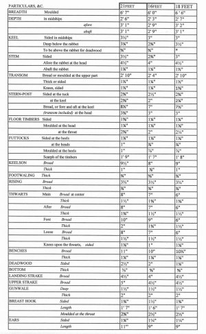
Scantlings spread sheet using full size dimensions. Sorry I could not get them all to fit on one page. The dimensions for the 21 foot and 16 foot cutters are from David Steel's The Elements and Practice of Naval Architecture. The 18 feet scantlings are a comprise of Steel's dimensions and the RMG drawing.
Allan

Allan


- Joined
- Apr 21, 2018
- Messages
- 881
- Points
- 353

Allan, I am enthralled by your cutter project.I am totally confused Pugwash. Where did I bring up politics? All I posted are drawings and pieces of wood and trying to show how to build an accurate small boat from scratch without a fully loaded machine shop.
Allan
My comment (post#24) was directed at the absurd posts 21&22.
Well, Pugwash, I am sorry that my post has caused any offense, although I must confess that I don’t see what there is to take offense at. Simply a parody meme of a famous line from a popular movie. All humor, no politics intended.Allan, I am enthralled by your cutter project.
My comment (post#24) was directed at the absurd posts 21&22.
If Allen finds my post inappropriate to his thread, I will delete it without hesitation.
Thank you kindly Pugwash, very much appreciatedAllan, I am enthralled by your cutter project.
Allan
- Joined
- Oct 23, 2018
- Messages
- 886
- Points
- 403

Really nice preparation. Allan
Thanks Christian. Should have some photos of the building set up of the formers on the building board shortly. Cutting most of the formers by hand is taking a while, but getting done.Really nice preparation
Allan
- Joined
- Oct 23, 2018
- Messages
- 886
- Points
- 403

Take the time you need, Allan. I will do the cutting jobs with my mill, but this brings sometimes also a lot of extra work. I found a small mistake at the stern construction of my sloop, which I couldn't see it with the buttock and horizontal lines and have to redraw it, before I can continue.
Also small mistakes are visible at the finished model, because I have much less tolerances than working with my scroll saw.
The classic way takes longer, but you don't have normally this kind of problems.
Also small mistakes are visible at the finished model, because I have much less tolerances than working with my scroll saw.
The classic way takes longer, but you don't have normally this kind of problems.
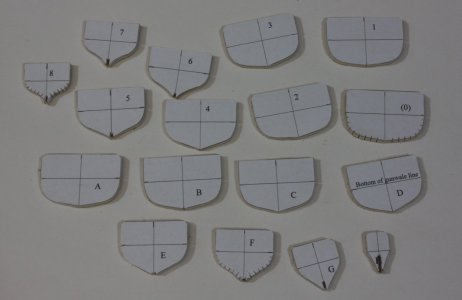
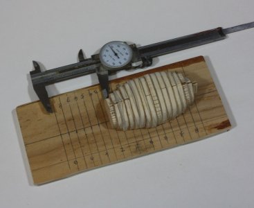
The formers have been all cut out using 0.20" plywood. I sandwiched them together to get their length then added the missing amount of space to calculate the size of the spacers between each former. I found that using just the plywood without smaller filler pieces in between sometimes led to pieces not holding tight in the past. I will be redoing this when my new caliper arrives tomorrow before making the filler pieces. The old one in the photo is questionable as it is not acting as smoothly as it once did. Sort of like its owner......



Showed up late here. Sorry about that. Great idea! Beautiful boat!
Just a quick question on a very minor issue... In looking at the RMG lines drawing and its derivatives posted above. The second thwart aft widens at its center to serve as what I suppose we can call the "mast partner." This is a common arrangement. However, the sheer plan does not indicate this widening of the second thwart aft. Nowhere do the plans indicate any sort of mast step beneath the second thwart aft which would be necessary to hold the mast in place at its foot. There is, however, what might be intended to serve as a mast step drawn on the sheer plan beneath the third thwart aft (the midships thwart.) Any idea why this is so beyond a simple draftsman's error?
Just a quick question on a very minor issue... In looking at the RMG lines drawing and its derivatives posted above. The second thwart aft widens at its center to serve as what I suppose we can call the "mast partner." This is a common arrangement. However, the sheer plan does not indicate this widening of the second thwart aft. Nowhere do the plans indicate any sort of mast step beneath the second thwart aft which would be necessary to hold the mast in place at its foot. There is, however, what might be intended to serve as a mast step drawn on the sheer plan beneath the third thwart aft (the midships thwart.) Any idea why this is so beyond a simple draftsman's error?
Great catch Bob.Nowhere do the plans indicate any sort of mast step beneath the second thwart aft which would be necessary to hold the mast in place at its foot.
Thanks for your input, it is very much appreciated!
Allan
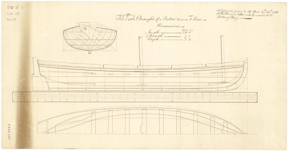
There is a ring bolt between the 2nd and 3rd thwarts
Interesting. Present day USN motor whaleboats have substantial lifting rings inboard on the keel for attaching lifting tackles. I believe their wooden cutters from around the turn of the 20th Century did also, but I'll have to check some of the plans in my copy of Standard Boats of the United States Navy (1905) to see if they did. I'll take a look and let you know.
I'll also do a bit of research to figure out how they launch their boats using those attachment points. Hanging them from a couple of tackles in the old days or from cranes or davits with winches modernly wouldn't seem to necessarily keep them upright, particularly in any sort of a sea. I'd expect they'd be very prone to tip one way or the other with the falls fetching up on the gunwales, dumping all and sundry into the drink! Maybe there's something in my old USN bosun's manuals or, for earlier times, Seamanship in the Age of Sail. I realize, of course, that folks may think I'm a bit obsessive about such details.
Another detail I'll mention in passing is that these Admiralty cutters, particularly when rigged with a boom, often have a sheet horse to carry the mainsheet block over the tiller in the customary fashion. One could also rig the mainsheet to run forward beneath the boom to a turning block on the boom and from there to another turning block shackled to a ring on the keel right around where the ring is on the keel in the cutter we're discussing. and thence to a belaying point or points completely out of the way of the tiller, but I don't know if there's any contemporary evidence of that being contemporary practice. (The Galway or Connemara hookers of the southwest Irish coast, which are believed to date back relatively unchanged to at least the mid 18th Century, are rigged in this manner with a purchase placed between the bottom of the middle of the boom and a ring bolt on the keel well forward of the helm, running thence aft to the helm where the fashion piece is extended port and starboard to provide two belaying posts for the mainsheet.)
Now, the "punchline" here is that there are not one, but at least two rigged contemporary ship's boat models in the NMG collection (and maybe more, but I've seen photos of two) which have their tillers running above their sheethorses! I discovered this when Chuck Passaro introduced his Syren cutter kit and then checked and noted the tiller on the Model Shipways Medway Longboat kit also designed by Chuck, similarly had its tiller running above its sheethorse. Obviously, this arrangement causes the mainsheet block on the sheethorse to foul the tiller, forcing it leward, every time the boat tacks or jibes, thereby causing the helmsman to lose control of the tiller. That's an even more serious matter in a shallow draft boat which has no centerboard! The photo of the Model Shipways longboat well illustrates the problem: It's obvious what happens to the tiller when the boom swings across from one side to the other?
I very delicately pointed this out to Chuck and he was adamantly defensive, telling me he'd actually gone to RMG and examined the contemporary models and that's the way they were rigged. I checked my library and found he was correct on that point, but countered that it was entirely possible that they were both rerigged by some restorer at who-knows-when in the past who didn't know what they were doing because it wasn't even a close call that the way they were rigged was incorrect on the basis of nothing more than simple mechanics, but Chuck refused to entertain that possibility at all, contending his models were exact copies of the contemporary models in the RMG. On that point we agreed that the kit models Chuck had designed were very nice looking, and very accurate models of models in the RMG.
The explanation of why the RMG contemporary models are so glaringly incorrectly rigged remains a mystery, and an object lesson to researchers of the risks of putting too much faith in accuracy of contemporary models, and particularly so with the majority which have been rigged and/or re-rigged over the centuries by unknown, and possibly unknowing, hands. The "contemporary ship modeling canon" is not infallible nor immune to heresy and this is the reason accuracy is so important, especially in well-executed models which may have the good fortune of lasting on into the future as putative parts of the historical record.
Syren Medway Longboat:
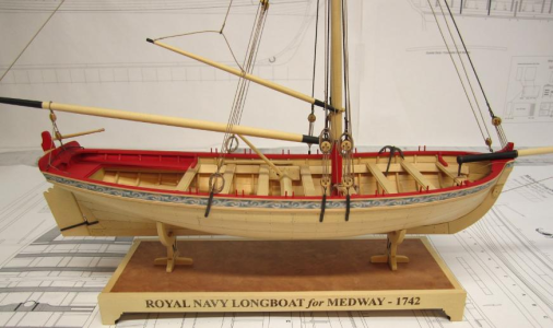
Medway Longboat (1742)
 syrenshipmodelcompany.com
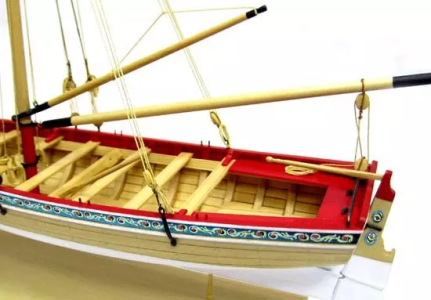

Model Shipways Longboat Model Ship Kit 1:48 SCALE 18th Century #MS1457 NEW | eBay
Replicated with every detail found in the original. Plus all the tools you'll need to bring your model to life at one low price. There are no plastic parts in it. Full size plan as well as a 20 page, color instruction book full of photographs takes the mystery out of assembly.
www.ebay.com
Galway hooker. Note the mainsheet tackle forward of the helm and the extended fashion timber "horns" on either side of the helm. In this picture, the mainsheet is being hauled and not belayed to the "horns" at the upper corners of the transom. The practice is to take a particular hitch around the horn which cannot jamb and can be cast off quickly if need be. This is a unique characteristic of this indigenous watercraft.

I remember this conversation and common sense says the rigging cannot work. As much as I rely on RMG for information, they admittedly are not without errors or incomplete data in their explanations. They are absolutely a caring and gracious team and I for one love to reach out to them but most of them are not trained as naval architects so cannot always help as much as they would like to. Considering the amount of information that is there an occasional error or incomplete explanation is understandable. My granddaughter will be starting college this fall and library science and archival studies are her focus. I am already pushing her to move to Greenwich and get a job at RMG when she graduates, or maybe do an internship there to get an inside track. Now if I could only talk her into taking a minor in naval architecture........The explanation of why the RMG contemporary models are so glaringly incorrectly rigged remains a mystery


