-

Win a Free Custom Engraved Brass Coin!!!
As a way to introduce our brass coins to the community, we will raffle off a free coin during the month of August. Follow link ABOVE for instructions for entering.
-

PRE-ORDER SHIPS IN SCALE TODAY!
The beloved Ships in Scale Magazine is back and charting a new course for 2026!
Discover new skills, new techniques, and new inspirations in every issue.
NOTE THAT OUR FIRST ISSUE WILL BE JAN/FEB 2026
You are using an out of date browser. It may not display this or other websites correctly.
You should upgrade or use an alternative browser.
You should upgrade or use an alternative browser.
Chaperon 1884 Stern Wheeler
- Thread starter Pathfinder65
- Start date
- Watchers 35
-
- Tags
- chaperon model shipways
Glad to have you in the audience. Feel free to kibitz as the build progresses.Looking forward to watching your build. I have this kit on my shelf. Good luck.
Jan
@WDO, welcome to the audience. My camera work is iPhone pointed shoot.looking forward to watching your build and lots of pictures.
Jan
The build begins:
The three pieces of keel have been glued together and the first two bulkheads are fixed and glued. The process is slow, as per the instructions I'll be adding the bulkheads from the center and working toward the bow and stern.
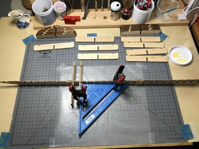
The spacing between the bulkheads is about 32mm. I've cleaned the char off bulkheads 10 - 19 and will be placing them next. According to the build instructions only bulkheads 1- 5 need to be faired.
To be continued:
Jan
The three pieces of keel have been glued together and the first two bulkheads are fixed and glued. The process is slow, as per the instructions I'll be adding the bulkheads from the center and working toward the bow and stern.

The spacing between the bulkheads is about 32mm. I've cleaned the char off bulkheads 10 - 19 and will be placing them next. According to the build instructions only bulkheads 1- 5 need to be faired.
To be continued:
Jan
@Bluebeard, thank you for that great offer. I'll keep that in mind as I bumble my way trough the build.Pathfinder:
Let me know if you need any pictures of the already build model we have at the shop. (Model Expo)
Jan
Adding bulkheads to keel:
Bulkheads 5 through 29 have been cleaned of Laser char and fixed to the keel. Bulkheads 1 - 4 have been cleaned of char but need a wee bit of whittling and sanding to the Laser engraved fairing line. I added the 1/8 X 1/8 stringers as per the instructions. "A note on the stringers, they are not long enough to reach from bulkhead 5 in the bow to bulkhead 29 in the stern."
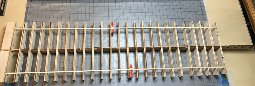
My imagineering fix was to add two blocks (the red pieces) to provide a splice point and to help with the rigidity of the stringers.
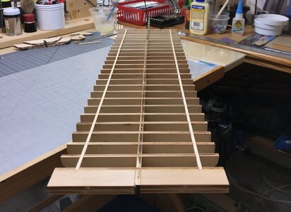
A look from the stern toward the bow shows that plan "A" worked, everything is nice and straight.
No complaints on the fit of the bulkhead or keel pieces, everything snapped in squarely and firmly. There weren't any fiddle or adjustment moments required
To be continued.
Jan
Bulkheads 5 through 29 have been cleaned of Laser char and fixed to the keel. Bulkheads 1 - 4 have been cleaned of char but need a wee bit of whittling and sanding to the Laser engraved fairing line. I added the 1/8 X 1/8 stringers as per the instructions. "A note on the stringers, they are not long enough to reach from bulkhead 5 in the bow to bulkhead 29 in the stern."

My imagineering fix was to add two blocks (the red pieces) to provide a splice point and to help with the rigidity of the stringers.

A look from the stern toward the bow shows that plan "A" worked, everything is nice and straight.
No complaints on the fit of the bulkhead or keel pieces, everything snapped in squarely and firmly. There weren't any fiddle or adjustment moments required
To be continued.
Jan
- Joined
- Jan 9, 2020
- Messages
- 10,566
- Points
- 938

Hello Jan. It is always nice to have a straight chassis as basis from which to work. These days I have begun to fair the bulkheads/frames before installation on the keel. That way I think I get more accuracy (the individual parts are much easier to work with) plus I cut down on the sanding time while assembled on the keel (an exercise I find awkward at the best of times).
Hi Heinrich. The instructions for the build suggest one should start the bulkhead/frame installation in the middle of the keel, working in both directions. They suggest doing a few at a time and letting the glue do its job. While that is happening to fair the bow insert and bulkhead/frames 1 - 5. So your idea seems to be very practical.
Jan
Jan
A bonus:
I can’t remember who provided this link, but I’ve spent hours perusing it.
Chaperon 3D video
Jan
I can’t remember who provided this link, but I’ve spent hours perusing it.
Chaperon 3D video
Jan
I‘ve found it fascinating, there are a lot of details that just aren’t normally viewable in regular photos. I’ve consumed a lot coffee watching this over and over. It would be a great help to other Sternwheeler builders.Now that does look amazing - and the best is that I can access it. I will have a closer look during the wee hours of the night.
Jan
What a great 3D video, Jan. It will helps you visualize the 2D drawing.A bonus:
I can’t remember who provided this link, but I’ve spent hours perusing it.
Chaperon 3D video
Jan
Nice details such as the braces&chains, interior etc etc.
Regards, Peter
I don't know about a creating a masterpiece, but I'm enjoying working on something different.Great 3D videoclip.
Perfect source of info for whoever wants to build the Chaperon besides you.
Pathfinder now I know you’ll create a masterpiece.
Jan
The “Ro-oH moments:
The instructions indicate that bulkheads/frames 1 - 5 and the bow filer needed to be trimmed/faired to the engraved laser line Using a SHARP #11 blade. I had to wait until the Admiral was out, since my “carving” skills are nil and I take meds that could be problematic if I were to slip .
.
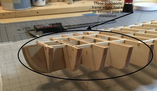
The results aren’t perfect, but no bandaids were needed.
The next step requires just a bit of carving on the edges of bulkhead/frame # 29, the rest of the shaping I can do by sanding.
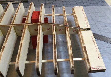
The red scribbles on piece #29B is the waste that has to be removed. That will be removed by trimming to shape and the final fairing.
Jan
The instructions indicate that bulkheads/frames 1 - 5 and the bow filer needed to be trimmed/faired to the engraved laser line Using a SHARP #11 blade. I had to wait until the Admiral was out, since my “carving” skills are nil and I take meds that could be problematic if I were to slip

The results aren’t perfect, but no bandaids were needed.
The next step requires just a bit of carving on the edges of bulkhead/frame # 29, the rest of the shaping I can do by sanding.

The red scribbles on piece #29B is the waste that has to be removed. That will be removed by trimming to shape and the final fairing.
Jan
Pathfinder 65, maybe this article will help you.The “Ro-oH moments:
The instructions indicate that bulkheads/frames 1 - 5 and the bow filer needed to be trimmed/faired to the engraved laser line Using a SHARP #11 blade. I had to wait until the Admiral was out, since my “carving” skills are nil and I take meds that could be problematic if I were to slip.
View attachment 248104
The results aren’t perfect, but no bandaids were needed.
The next step requires just a bit of carving on the edges of bulkhead/frame # 29, the rest of the shaping I can do by sanding.
View attachment 248105
The red scribbles on piece #29B is the waste that has to be removed. That will be removed by trimming to shape and the final fairing.
Jan
Removing the beetle. What's this?
Already at the first stages of building a ship model, a novice modeler will come across a number of terms and concepts, the meanings of which are not obvious and require clarification.
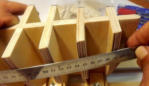
One of the operations that must be performed when installing frames on a keel frame is removing the bead, i.e. removal of bevels on the ribs of the frames. It can also be called balking, barking, etc.
The marine dictionary explains the concept: In shipbuilding practice, a small angle is called the angle between the shelves of the frame square, when it is more or less than a straight one.
In particular, when building small boats and yachts, the necessary for removing the bead is determined by applying a flexible wooden strip and picking out the protruding parts under the control strip. After all measurements, the plane of the end part of the frames is processed with a plane according to these "beacons", which is well described by S. Vetrov in "Pioneer Shipyard".
In ship modeling, the meaning of this operation is that, both before installing the frames on the glue, and after gluing, it is necessary in this way to process the outer surface of the future hull frame - the end parts of the frames, so that with further rough and final plating of the ship, the processed strips lay down tightly to the frame, with the desired bend, without kinks and dips.
Manufacturers of kits for assembly can engrave outlines for removing bevels (bevels) on parts (in particular, the Russian manufacturer of wooden kits "Master Ship" on the "Phoenix" model). The main removal of the bead is carried out, in this case, before the installation of the frames along the lines of laser engraving applied by the manufacturer, and the final processing is done after planting on the glue.
In general, in order to correctly and efficiently remove the bead, ensuring in the future the symmetry and correct even contours of the hull, the novice modeler will be faced with the need to somehow fix the keel frame on the working surface. This is important for aligning the strict perpendicularity of the frame-keel ligament, and as a result, obtaining the correct smooth contour of the hull as a result of processing. In this case, the slipway is not a whim, but an urgent need. Each frame may have to be removed and installed several times, checking with a batten or a thin wooden ruler, gradually working and adjusting its edge and it is important not to waste time every time you install it to align it. A staple flap, installed in the required place of the frame, at the right angle to the securely fixed keel of the future model hull, will greatly facilitate the task.
The slipway will also be useful if the modeler decides to remove the bevels from the already glued body frame, which in some cases makes sense.
Each modeler performs rough processing of frames, removal of the bevel in a convenient way for him: with the help of a model knife, a file or a file, with a sandpaper fixed in a sandpaper, etc. or mechanizing a delicate process in their own way.
Before final finishing, the frames are checked again for perpendicularity and glued. After drying, before sanding, it is recommended to install temporary spacers between the frames in the spacing - bars made of a suitable non-solid material - balsa or similar wood, even dense foam will do. The frame of the body, strengthened in this way, is finally processed with a thin sandpaper fixed on a sufficiently long sandpaper. All these actions allow in the future to have a frame of the model body with a consistent geometry that is convenient for plating and does not require additional processing.


