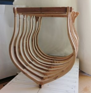
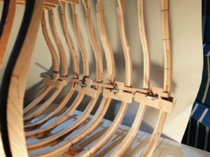
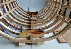
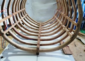
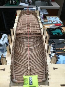
Cross Section - HMS Leopard 4th Rate 1790 - 1:44

Joined
Dec 15, 2019
Messages
99
Points
143

The build of my other model, H.M.S. Leopard at 1:80 took almost 9 years, so, at this time I didn't want to take on another full-on build of a complete ship.
As I have basic drawings/plans of Leopard I'm going to have a go at a cross section. Since a section will require a lot less space for the finished item I wanted to exploit that and have increased the scale considerably from 1:80 to 1:44.
. . . and to explain about the unusual scale of 1:44 - - - I intended to have the previous drawings/plans at 1:80 doubled up and asked for that at the copy shop. The enlarged copies came out at a little less twice the size. At the widest point on my body plan drawing the moulded breadth measures exactly 11 inches. Compared to the moulded breadth of the actual ship at 39 feet 10 inches that works out at 1:43.45 --- so, its official model scale will be called "1:44".
OK, that's that out of the way.
As for the actual drawings and plans that I will need, some modifications have to be made before I can even think about creating more sawdust.
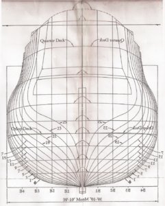
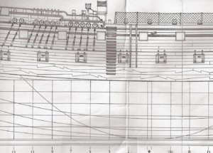
When I built my previous Leopard it was a bulkhead model so the body plan was sufficient for making bulkheads . . . but this section will require frames so here are all I have in the way of drawings >>>
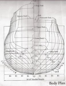
0001-Body Plan.jpg
and this drawing of a section around midships just ahead of the main mast looking aft >>>
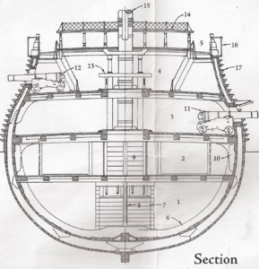
0005-Section.jpg


The section drawing above is enough as a rough guide to the basic shape of the mid-ship frame but I will have to modify the body plan for the nine frames I intend to make. It won't be a fully-framed section but instead the frames will equate to the positions of the bulkheads from 13 to (B) shown in the plan below >>>
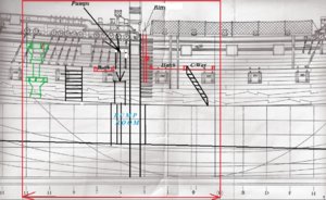
Mid-side - Copy.jpg
It will be a little longer than most cross sections I have seen as I want it to display from just ahead of the companionway forward of the main mast back to the two capstans. >>>
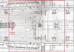
00070 Plan.jpg
I will need more than the 'half frames' that can be obtained from the body plan, so, I had the image flipped horizontally and made a few copies >>>
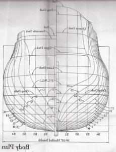
0002-BodyPlan flip.jpg
I cut two of the flipped copies down the centre line and pasted them onto original copies and ended up with these 'full frame' copies >>>
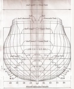
0004-Frames - fore.jpg
0003-Frames - Aft.jpg
These two copies went to the copy shop and I had 12 of the aft frames and 6 of the forward frame drawings reproduced at 1:44.
I should be able to utilise these to draft the shape of each of the frames that I'll need . . . the section drawing will hopefully help me get close to the proportional thickness of the frames as they gradually taper from bottom to top.
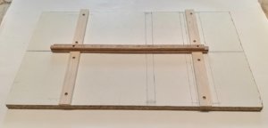
So far I have prepared a baseboard on which to build the model. It is a leftover piece of white melamine covered board and it's ideal as it's very stable and flat, and being white, it's so easy to draw the markings I'll need. Here it has the centreline drawn on along with 3 of the 9 frame positions also drawn on. ...
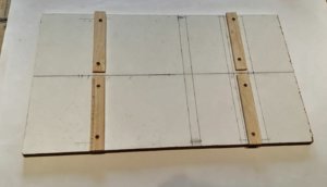
Baseboard.jpg
The uncut blank for the keel (with rabbet cut on milling machine) is here being centred on the board >>>
Baseboard Keel .jpg
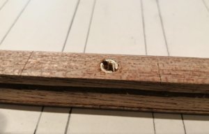
I intend securing the keel to the board with two of these threaded brass inserts >>>
Keel nuts 2.jpg
These inserts hold the keel very securely on to the base board and I hope to use them when the model is finished to hold it on to the final display board.
 
Hello Jim from another Jim. If I am not mistaken, @Donnie said today that cross section models getting real popular among SOS members. We are glad you decide to share your build log with us. Many thanks! I am taking my seat and will be watching with huge interest. :)
 
Hi Jim and Don, thanks for your comments and to the others for the likes and all who have visited.

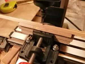
An update: My previous post showed the rough blank of the keel with the rebate/rabbet already cut. That took the honour of being the first part of the build to generate sawdust. The rebate was cut on the milling machine using this jig >
Jig.jpg
Jig -.jpg
I didn't use the machine in the conventional way by winding the travelling table, but instead kept the table still and moved the keel along the jig into the spinning cutter.
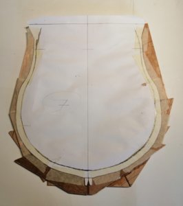
Sawdust phase two: Over three days I cut all nine frames required for the build. After cutting and laminating about 13 pieces ( a mixture of beech on one side and plywood on the other) for each frame, next task was to cut out the nine copies of the body plan.
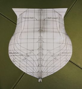
Here's the cut-out copy of frame #11 >
Cut-out.jpg
The copy is reversed and attached to the blank for the frame. I opted not to glue them on but used masking tape instead. At this stage only the outside of the frame is defined, and the inner face has to be drawn, freehand, onto the blank side of the paper copy. Because of the taped-on (un-glued) paper copy, the INNER side of the frame MUST be cut first. If the outer face is cut first, the paper copy with its inner cut line is removed from the frame and the line would have to drawn on to the frame blank again.
Here, a blank prior to meeting the bandsaw for cutting out >
Frame.jpg
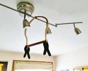
A light sanding to clear most of the bandsaw marks and the next stage. As these frames appear very delicate the first thing I did was to try to stabilise them somewhat by gluing a stiffener across the extra length of the top. Here's one in my 'safe place' while the glue dries >
Frame cure.jpg
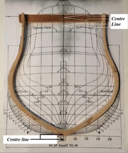
Each frame was laid directly on an uncut copy of the body plan to establish the centre line at the keel as well as on the glued-on top stabilising plywood >
Centre line layout.jpg
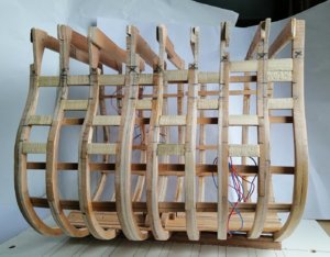
Then there were nine >
Frames.jpg
I have no plans for a framing jig and didn't want all the extra planning, thinking (and eventually getting it wrong!) involved in producing a framing jig - - - so I didn't!
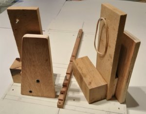
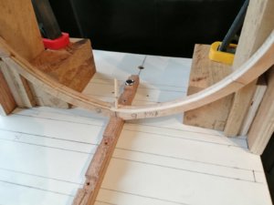
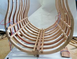
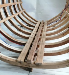
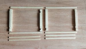
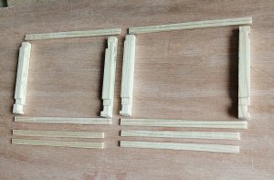
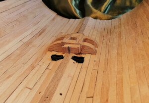
But I had to devise something to ensure the frames would be properly centred on the keel at attachment time. A lot of thinking later brought me to make these >
0005.jpg
They'll need a bit of explanation. They are mirror images of each other.
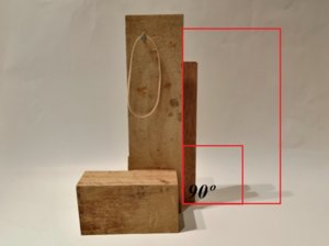
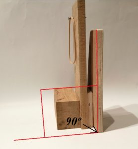
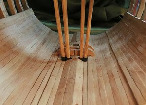
Each of them have two vertical pieces, each one being perpendicular to the "floor" >
0006.jpg
. . . and on this face >
0007.jpg
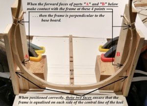
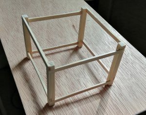
Perhaps the following photo may help explain how these work >

Keel-Frame.jpg
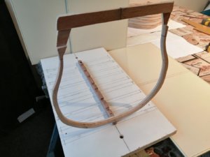
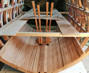
Further to these two 'jigs' I had to create something else that would hopefully ensure that the top stabiliser would be properly centred over the keel.
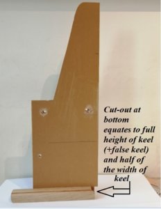
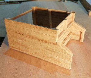
This is simply another piece of board which had a factory cut perfect right angle, attached to a single piece of oak just to make it more stable as it sits on the melamine baseboard. As the bottom edge has to line up with the keel's centre line, a cut-out at the bottom was required. This photo might help? >
Square cut-out 1.jpg
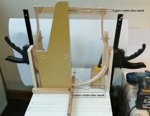
. . . and hopefully, the following photo will explain how that 'device' might help ensure the top centre line is exactly where it should be >
Square 2.jpg

Well, the above is the theory - - - now to see if it works!
 
Thanks for your comment, Uwe, and to the others for the likes and visits.

So far, my only mention of the keel was to say that I used the milling machine to cut the rebates.
The keel, keelson and false keel were all cut from the same piece of mahogany.
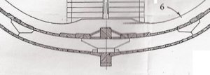
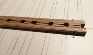
The design of the keel and keelson may be a little bit of my own idea and that is because of the way I have made the frames. As I only have one image of only one of the frames, and that frame is shown as having no cut-out/mortice under the floor timber where it meets the keel, my frames also just have a continuous profile without any cut-out. Here's the floor timber as shown on that drawing of the midships frame >
Floor.jpg
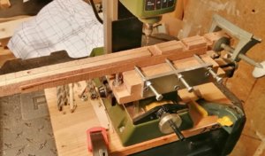
So, I decided to make fairly large cut-outs in the keel and keelson in order that the frames would have a fairly secure place to live. I clamped the keel and keelson together and took them to the mill where the cut-outs were done >
Keel-Keelson Mill-.jpg
Keel-Keelson.jpg
Back to talking frames.
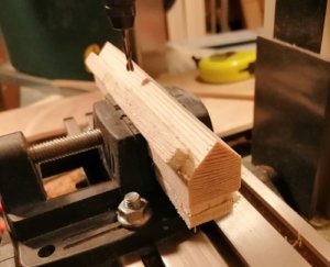
Before any glue-ups happened, each frame was placed and held in its respective place on the keel while a 3mm hole for a dowel was drilled down through the floor of the frame and part way into the keel >

Dowel-.jpg
Before final commitment to the glue, all frames were placed in their positions with a dowel down through each one. With just dry dowels there, I was encouraged for a reasonable success with the glue. Here with just the dry dowels >
Dowels.jpg
A word about the initial glue-up of the frame blanks that I forgot to mention :- for the first 2 or 3 frames I used PVA glue but quite soon after, a few of the joints failed. I had previously had a few minor failures with that same glue so I had to re-do these failed joints with my "T.N.P." glue ("Take No Prisoners" glue). The remaining frames were all done with T.N.P. glue. (T.N.P. glue is probably better known as 'Epoxy Resin' -- no failures with the epoxy!)
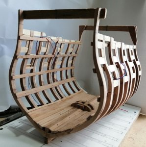
The first frame now permanently in its new home >
One.jpg
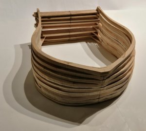
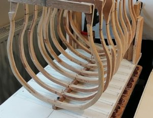
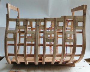
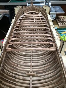
Then, within 3 days, all nine frames are home >
Nine.jpg
That photo tells me that some fairing of the frames will be happening, although probably not as much as I was expecting.
Now that all frames are secured my main initial concern was to stabilise them. First thought was to glue in fillers between the frame tops but at this point their positions weren't established so I opted to begin fixing the deck clamps starting at the orlop and working up.
My previous "invention" for centralising the frames on the board was found useful for transferring the marks for the clamp positions onto the frames. Starting with the orlop, the fore and aft marks (being around 4mm different to each other) were pencilled on the 'jig' and from there onto the forward and aft frames. The first of the orlop clamps glued on and clamped >
Clamp - Orlop.jpg
That was great - - - except that was my first mistake!
From the body plan I marked the positions I needed, but instead of the top of the clamp, I had marked the top of the deck, so I had glued the clamp on at the height of the deck instead of at the height of the underside of the deck beam. That epoxy resin sure is good stuff -- it takes no prisoners! That deck clamp DID NOT want to come off! I had to drill into each end and then carefully prise it off the other seven frames. A new clamp was made and fitted . . . and a lesson learned!
After fitting both orlop and lower gun deck clamps I wanted to get the keelson in position. My vision for the finished project sees it with several lanterns lit throughout the section. I don't know if I will be successful in this electrical part of the project but, in preparation, I have introduced, through the keel at two positions, the wiring. I wanted the wiring in position before the keelson as it comes up through the keel and I want it to be hidden between the hull planking and the ceiling planking.
Here's the keelson in the clamps and the red and blue wiring visible at both ends >
Keelson clamps.jpg
. . . and after the T.N.P. glue had done its job >
Keelson.jpg

Even with just the orlop and lower deck clamps on, the whole structure is remarkably stiffened up now.
 
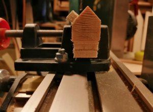
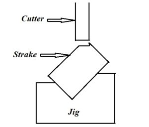
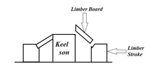
Limber strakes were next for making more sawdust. I wanted there to be small ledge or 'shelf' on which the limber boards would rest on the top corner of the strakes, so I took each of the inner strakes and placed it in the same jig I had used for creating the rebates in the keel at the milling machine >
Jig --.jpg
It's not too clear what's happening in the photo above so the following drawing shows it clearer >
Strake jig.jpg
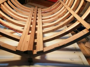
The inner limber strakes >
Limber Strakes.jpg
and with the outer strakes >
Limb. Str-.jpg
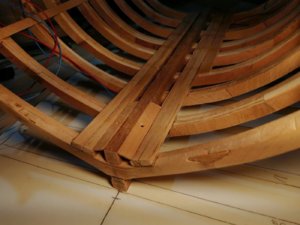
The first limber board is cut >
Limb Bd.jpg
and in position >
Limb Bd-.jpg
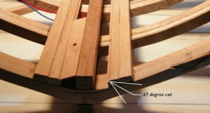
The next photo shows the 45 degree cut made in the limber strakes >
Limb cut.jpg
That angled cut sure made it easy for the boards to locate >
Limb cut-.jpg
Board #2 >
Limb Bd 2.jpg
At this point I realised it would be smart to make and fit the mast step before fitting more limber boards.
IMG_20200310_103710.jpg
IMG_20200310_103622.jpg
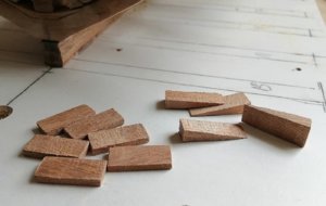
Step wedges and chocks >
Mast wedges+chocks.jpg
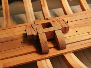
Initially, I fitted all of the above along with the mast step >
Mast Wedges Chocks.jpg
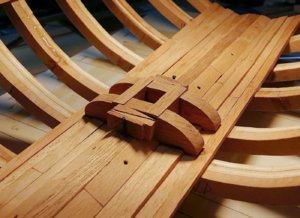
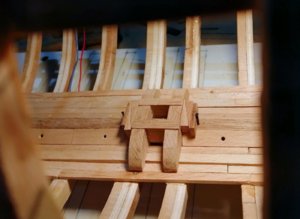
But that just looked like too many chocks so I removed two chocks from each side >
Mast step wedges-.jpg
Mast step wedges--.jpg
 
After fitting the upper gun and quarterdeck clamps fillers were added at the frame tops and also around the areas of the gunports. >
Fillers.jpg
There is an "X" drawn near the top of every frame with a line under each "X". These lines mark the approximate cut-off points for the frames.
In the next photo all but the end frames have been cut down to close to finished height and the final positions and sizes of the gunports have been established. In my other build I framed all 48 gunports before any hull planking began and that worked well for me so I have done the same here. >
Frames cut.jpg
I left the two end frames uncut at this stage as they may prove useful at times when the section is upside down for work off the base board.
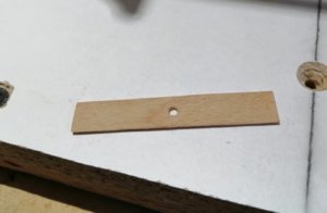
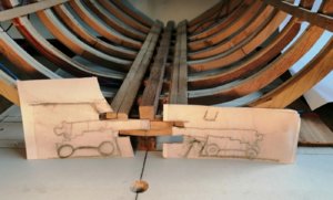
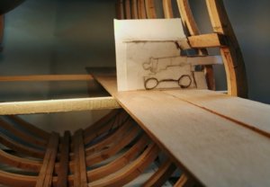
To enable me to establish the heights of the tops and bottoms of the gunports I used cut-outs of 2 very badly drawn guns along with dummy deck beams and deck planking. If you wish, you may have a laugh at the following image >
Dummy guns.jpg
. . . and here's the larger of the "guns" on the dummy beams and planking >

G.P. Ht.jpg
These "drawings" may have looked ridiculous but they served their purpose and probably will never be seen again!

I used measurements from the side plan to mark the fore and aft limits of each port >

Body plan side - mid section.jpg

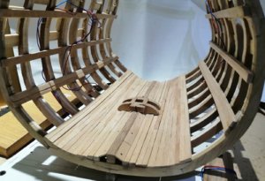
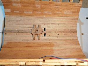
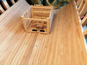
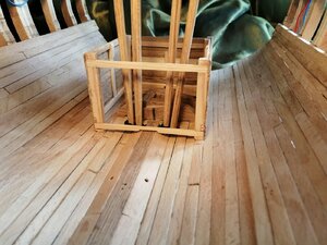
Back down in the hold some progress with the footwaling and thick stuff. This has seemed to take much longer than I expected, probably due in part to having to work with the 4 different thicknesses of the planks required down here. >
IMG_20200411_123820.jpg
IMG_20200415_214041.jpg
IMG_20200412_155929.jpg
 
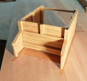
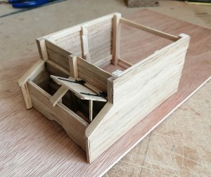
Lower well and shot locker. The basic parts of the frame for the well >
Well frame.jpg
Well frame--.jpg
Well frame...jpg
For that frame I used softwood as my supply of beech is running low and with the Covid 19 lockdown there are no timber merchants open, and don't look like opening any time soon.
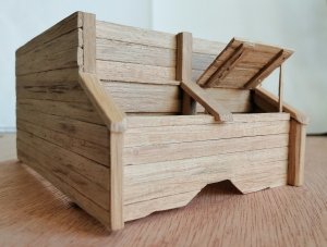
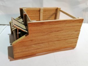
As I have more oak than I do of beech, I used oak for the planking on the well and shot locker >
IMG_20200404_220508.jpg
IMG_20200404_220029.jpg
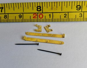
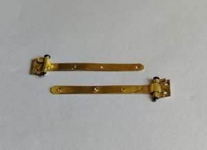
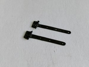
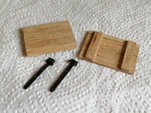
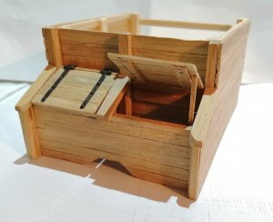
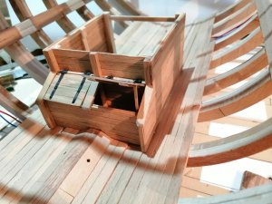
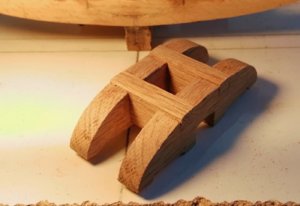
The hinges for the shot locker lids was my first attempt at making working hinges -- apart from the rudder hinges on my other previous build. (The gun port hinges on that model were just dummy, static hinges.) >
S.L. Hinges.jpg
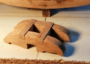
S.L. Hinges-.jpg
S.L. Hinges--.jpg
Shot locker lid.jpg
I chose to have one of the lids propped open >
S.L.W..jpg
S.L.W.--.jpg
With both lids >
S.L.W.----.jpg
S.L.W.-----.jpg
I left the back of the well open without planking for two reasons --

1) The finished model will probably be displayed with the aft end facing a wall so the back of the well won't be seen, BUT - - -
2) If it is sometimes possible to view in from the rear, all the 'stuff' going on in the well, the mastfoot and step and the pump tubes will be able to be viewed.

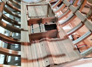
The well and shot locker go for a test drive >
SLWH----.jpg
SLWH--.jpg
 
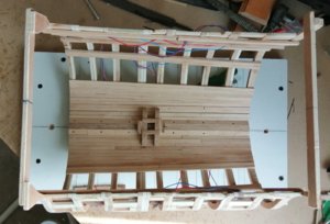
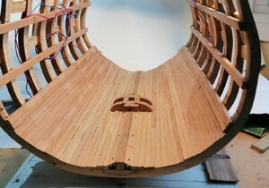
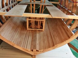
Finishing the internal planking in the hold, (the footwaling, ceiling and thick stuff) has been something of a milestone for this build. I didn't expect this should be regarded as a milestone but it has taken me much longer than I had expected >
Hold floor.jpg
During that time I was also diverting to other small projects for the build. This build is proving substantially different to my other build as that model was fully planked, so all the 'stuff' in the hold and orlop and most of the lower gun deck were not visible in the finished model so I didn't have to make any of that 'stuff'.
Sailors needed rum, beer and other provisions and for some of these provisions, barrels were needed.
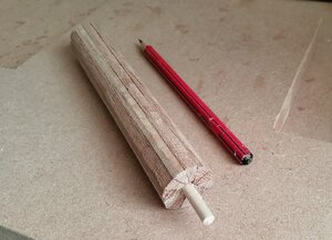
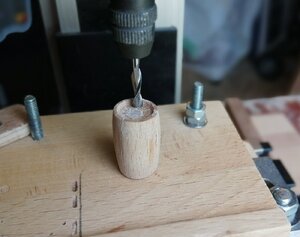
This was a new challenge for me. I did a single small barrel as a 'starter experiment' to see how it would work for me. The following is the blank that I used to create the second batch of 4 barrels. I adopted that idea from having seen it on other build logs >
Barrel Blank.jpg
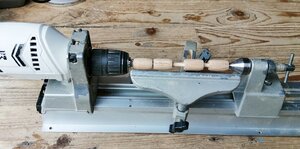
I don't have a proper lathe - just a jig into which an electric drill fits and the drill's chuck is what is used to hold and spin the workpiece. This is perfectly adequate for the basic turning but I am unable to hollow out the tops of the barrels in the lathe/jig so that task is done on the milling machine.
IMG_20200509_162949.jpg
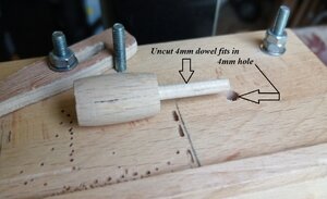
I have to leave a little of the 'dowel' on each barrel when I separate them for the reason shown in the next photo >
Barrel cut.jpg
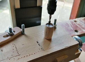
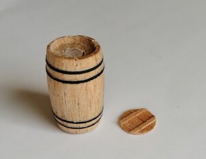
The barrel with its dowel sits in that hole in that jig I made to fit on the milling machine table. The cutter is brought down to where it needs to be to start cutting out the hollow and the barrel is positioned by moving the table left/right and in/out until the required position is achieved. The barrel is then slowly spun by my fingers while the cutter removes material from inside the 'rim' of the barrel >
IMG_20200412_130834.jpg
IMG_20200412_131001.jpg
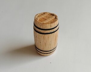
The first 'experiment' >
Barrel-lid.jpg
IMG_20200412_154825.jpg
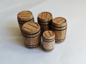
. . . and with the four larger barrels from the 'lathe image' above >
Barrels.jpg
 
Hi Jim,
The bands are simply black paper just glued on with PVA.
You're right, they aren't all that difficult to make . . . but very time consuming!
But hey! - - - I'm retired and we're in the middle of this lockdown so I should have time to make the other 20 or so barrels for the model!
 
Hey Jim,
I've finally got up to date on you build and she looks marvelous. You have incorporated many details that I will eventually use. I do plan to also add crates and if I'm not mistaken, ships usually had spare anchors stored in the main hold tied to columns. I have to do a bit of research in that department but its food for thought.

Raymond
 
Hi Raymond,
Thank you for your comment. I'm always trying to come up with ideas of what to include in the hold. I keep looking at other builds, especially sections, trying to pinch some ideas! I'll be looking at your suggestion of crates although I'm not very familiar with what 18th century crates would look like. Any suggestions as to where I can see these would be welcome.

It may seem a bit early in this build to mention pumps - - but while sailing ships wouldn't go anywhere without sails and would be fairly uncontrollable without a rudder, without pumps they wouldn't stay afloat for very long. This, being a section, will neither have sails nor a rudder so I thought at least it should have pumps.
Just a few weeks ago I knew not a lot about pumps but my research and the asking of questions has turned up some good information, although it wasn't the easiest to find.

The Elm Tree pumps: Neither "The 50 Gun Ship" book nor any of the plans/drawings that I have of the 50 gun ship make any mention of these pumps. In one answer to my question on Google , one "knowledgeable" person (not on a model ship forum) said these were the chain pumps -- that is INCORRECT -- the chain pumps are completely different. The elm tree pumps (or brake pumps) were used to draw water either directly from the sea (by means of a "hole in the hull") or from a watertight cistern in the hold which in turn was filled by drawing water through a pipe or pipes that also exited through the hull. The function of these pumps was to provide water for deck washing and firefighting if required.

The Chain Pumps: The purpose of these pumps was to put water back where it is supposed to be -- in the sea. These were always located on the lower gun deck, or whichever deck that was the first above the ship's natural waterline. I'm guessing that to have added longer tubes to reach a higher deck would increase the length of the chain and, combined with the weight of the extra water that would be lifted, would add considerably to the already heavy load on the men working the pumps.

Each of these two types of pump had a different advantage over the other -- the chain pumps could lift large amounts of water in a short time but not under pressure, so were of little use for hosing decks or fires. (I seem to recall reading that these pumps could lift about a ton of water in around one minute.)
The elm tree/brake pumps could deliver water under pressure and to higher decks, but were considerably less efficient at drawing a large volume of water in a short time.

I always try to think ahead in the build in my attempts not to have to do something that should have been done earlier - - well, I don't always succeed in that.
While I was recently pleased to have finished all the internal planking in the hold, I've just had the minor inconvenience of having to cut through a couple of limber boards and strakes for the holes for the sumps of the chain pumps. These 2 cuts took the best part of 2 hours, including the repairs to a couple of the limber board and re-gluing them back in. If I were to do a similar build again I would first calculate the position of the holes and leave appropriate gaps in the limber boards and strakes!
The sump holes >
C Pump cut.jpg
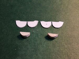
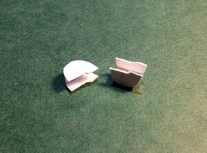
I made the 'metal' sumps from card and made a couple of 'half-moon' shaped pieces of wood to hold them together >
C Pump sump.jpg
C Pump sump..jpg

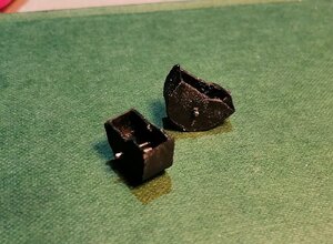
. . . and painted before a test fit. There should be inlet holes in these sumps but as they'll never be seen way down in the bottom of the ship, mine won't have these holes. >
C Pump sump....jpg
Dry fitted in their homes >
IMG_20200514_171444.jpg
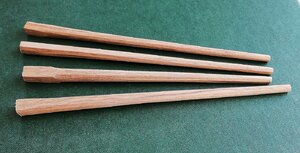
The pump tubes. (These are for the chain pumps) I used my hand held belt sander - very carefully! to create the taper, then by hand, using a sanding block, attempted to achieve their octagonal shape >
Tubes..jpg
These tubes are overlength at this time and will remain so until I can more accurately cut them to size when I make the cisterns when working on the lower deck. Tubes having a test drive >
IMG_20200514_153409.jpg
IMG_20200514_153425.jpg

IMG_20200514_171532.jpg
IMG_20200514_171917.jpg
IMG_20200514_172037.jpg

Next, it'll be the turn of the elm tree pump tubes . . . no sumps for them -- they just exit out through the hull near the keel, ahead of the main mast.
 
Thanks for your comment, Uwe, and to the others for the likes and visits.

So far, my only mention of the keel was to say that I used the milling machine to cut the rebates.
The keel, keelson and false keel were all cut from the same piece of mahogany.
The design of the keel and keelson may be a little bit of my own idea and that is because of the way I have made the frames. As I only have one image of only one of the frames, and that frame is shown as having no cut-out/mortice under the floor timber where it meets the keel, my frames

Hi Raymond,
Thank you for your comment. I'm always trying to come up with ideas of what to include in the hold. I keep looking at other builds, especially sections, trying to pinch some ideas! I'll be looking at your suggestion of crates although I'm not very familiar with what 18th century crates would look like. Any suggestions as to where I can see these would be welcome.

It may seem a bit early in this build to mention pumps - - but while sailing ships wouldn't go anywhere without sails and would be fairly uncontrollable without a rudder, without pumps they wouldn't stay afloat for very long. This, being a section, will neither have sails nor a rudder so I thought at least it should have pumps.
Just a few weeks ago I knew not a lot about pumps but my research and the asking of questions has turned up some good information, although it wasn't the easiest to find.

The Elm Tree pumps: Neither "The 50 Gun Ship" book nor any of the plans/drawings that I have of the 50 gun ship make any mention of these pumps. In one answer to my question on Google , one "knowledgeable" person (not on a model ship forum) said these were the chain pumps -- that is INCORRECT -- the chain pumps are completely different. The elm tree pumps (or brake pumps) were used to draw water either directly from the sea (by means of a "hole in the hull") or from a watertight cistern in the hold which in turn was filled by drawing water through a pipe or pipes that also exited through the hull. The function of these pumps was to provide water for deck washing and firefighting if required.

The Chain Pumps: The purpose of these pumps was to put water back where it is supposed to be -- in the sea. These were always located on the lower gun deck, or whichever deck that was the first above the ship's natural waterline. I'm guessing that to have added longer tubes to reach a higher deck would increase the length of the chain and, combined with the weight of the extra water that would be lifted, would add considerably to the already heavy load on the men working the pumps.

Each of these two types of pump had a different advantage over the other -- the chain pumps could lift large amounts of water in a short time but not under pressure, so were of little use for hosing decks or fires. (I seem to recall reading that these pumps could lift about a ton of water in around one minute.)
The elm tree/brake pumps could deliver water under pressure and to higher decks, but were considerably less efficient at drawing a large volume of water in a short time.

I always try to think ahead in the build in my attempts not to have to do something that should have been done earlier - - well, I don't always succeed in that.
While I was recently pleased to have finished all the internal planking in the hold, I've just had the minor inconvenience of having to cut through a couple of limber boards and strakes for the holes for the sumps of the chain pumps. These 2 cuts took the best part of 2 hours, including the repairs to a couple of the limber board and re-gluing them back in. If I were to do a similar build again I would first calculate the position of the holes and leave appropriate gaps in the limber boards and strakes!
The sump holes >
View attachment 151290
I made the 'metal' sumps from card and made a couple of 'half-moon' shaped pieces of wood to hold them together >
View attachment 151291
View attachment 151292

. . . and painted before a test fit. There should be inlet holes in these sumps but as they'll never be seen way down in the bottom of the ship, mine won't have these holes. >
View attachment 151294
Dry fitted in their homes >
View attachment 151295
The pump tubes. (These are for the chain pumps) I used my hand held belt sander - very carefully! to create the taper, then by hand, using a sanding block, attempted to achieve their octagonal shape >
View attachment 151296
These tubes are overlength at this time and will remain so until I can more accurately cut them to size when I make the cisterns when working on the lower deck. Tubes having a test drive >
View attachment 151297
View attachment 151298

View attachment 151299
View attachment 151300
View attachment 151301

Next, it'll be the turn of the elm tree pump tubes . . . no sumps for them -- they just exit out through the hull near the keel, ahead of the main mast.
also just have a continuous profile without any cut-out. Here's the floor timber as shown on that drawing of the midships frame >
View attachment 139080
So, I decided to make fairly large cut-outs in the keel and keelson in order that the frames would have a fairly secure place to live. I clamped the keel and keelson together and took them to the mill where the cut-outs were done >
View attachment 139081
View attachment 139082
Back to talking frames.
Before any glue-ups happened, each frame was placed and held in its respective place on the keel while a 3mm hole for a dowel was drilled down through the floor of the frame and part way into the keel >

View attachment 139084
Before final commitment to the glue, all frames were placed in their positions with a dowel down through each one. With just dry dowels there, I was encouraged for a reasonable success with the glue. Here with just the dry dowels >
View attachment 139085
A word about the initial glue-up of the frame blanks that I forgot to mention :- for the first 2 or 3 frames I used PVA glue but quite soon after, a few of the joints failed. I had previously had a few minor failures with that same glue so I had to re-do these failed joints with my "T.N.P." glue ("Take No Prisoners" glue). The remaining frames were all done with T.N.P. glue. (T.N.P. glue is probably better known as 'Epoxy Resin' -- no failures with the epoxy!)
The first frame now permanently in its new home >
View attachment 139086
Then, within 3 days, all nine frames are home >
View attachment 139087
That photo tells me that some fairing of the frames will be happening, although probably not as much as I was expecting.
Now that all frames are secured my main initial concern was to stabilise them. First thought was to glue in fillers between the frame tops but at this point their positions weren't established so I opted to begin fixing the deck clamps starting at the orlop and working up.
My previous "invention" for centralising the frames on the board was found useful for transferring the marks for the clamp positions onto the frames. Starting with the orlop, the fore and aft marks (being around 4mm different to each other) were pencilled on the 'jig' and from there onto the forward and aft frames. The first of the orlop clamps glued on and clamped >
View attachment 139088
That was great - - - except that was my first mistake!
From the body plan I marked the positions I needed, but instead of the top of the clamp, I had marked the top of the deck, so I had glued the clamp on at the height of the deck instead of at the height of the underside of the deck beam. That epoxy resin sure is good stuff -- it takes no prisoners! That deck clamp DID NOT want to come off! I had to drill into each end and then carefully prise it off the other seven frames. A new clamp was made and fitted . . . and a lesson learned!
After fitting both orlop and lower gun deck clamps I wanted to get the keelson in position. My vision for the finished project sees it with several lanterns lit throughout the section. I don't know if I will be successful in this electrical part of the project but, in preparation, I have introduced, through the keel at two positions, the wiring. I wanted the wiring in position before the keelson as it comes up through the keel and I want it to be hidden between the hull planking and the ceiling planking.
Here's the keelson in the clamps and the red and blue wiring visible at both ends >
View attachment 139100
. . . and after the T.N.P. glue had done its job >
View attachment 139101

Even with just the orlop and lower deck clamps on, the whole structure is remarkably stiffened up now.

Jim
Wow, ! This is a very impressive build, and the step-by-step practicum is explained and illustrated so well that even a dunce beginning modeler like me can understand it. I am learning a lot from your process and from all of your inventions and tricks. I especially like your milling jigs, and your drawn-out cannon are genial. May I copy the idea ? I am building a CAF kit of HMS Enterprise and your build will be immensely helpful. I've bookmarked it....
We have something in common: Earlier in my build, I thought I had totally misplaced the main deck deck-clamps, but it turned out that my plans had two lines, one marking the finished deck height, and another the top of the deck clamp-the problem was that the lines were unmarked...Thankfully, I had placed my deck clamps at the correct level, so I did not have to tear them out. However, I had totally misplaced the level of the foredeck clamps- A couple of days ago, I cut them out (they had been glued and trunneled, so it was tedious to do ) and carefully and re-positioned them. Anyway, thanks a lot and Congratulations. !
Alex61358CE5-5C46-4914-B667-B0877FAE7538.jpeg
Here are the foredeck clamps. There are two per side-the lower one was placed initially, and the second one on top- but still not at the correct level. (long embarrassing explanation as to why I did that.)

54F27254-8ED9-468F-8272-651CAAC70C70.jpeg This image shows the re-positioned foredeck deck clamp. The lower deck clamps have been partially removed. Notice my laser pointer that I am using to center deck beams and structures.
 
Hi Alex,
Thank you for your comments and to the others for the likes and visits.

Alex, you said "even a dunce beginning modeler like me" ~~~ well, if that model I see in your post is yours then you're in the wrong class! That's not the work of a 'dunce beginning modeler' ! All that framing and deck beam work is amazing. This cross section I'm doing is only my second ever model and it's the first with frames instead of bulkheads -- BUT it only has NINE frames and I know how much work that was and to get them onto the keel.
You also asked, "May I copy the idea ?" ~~~ I'd be delighted to think that anyone would copy anything that I've posted. There have been a few things on these forums that I've also copied!
If I may ask you -- you said "I am building a CAF kit of HMS Enterprise" ~~~ is that the model in the photos you have posted above?
I've never done a kit and, apart from cross section kits, I've never seen a kit of a fully framed model; I've only ever seen bulkhead models in kit form.
 
I knew of two pumps on ships, but didn't know why till I read your information in the build log.

This is why I like the forums so much, I expand my ship design and function knowledge most every day, by reading what others are showing and telling us.

Thanks for the information and photos.

Kurt K
 
Back
Top